Views: 2366 Author: Site Editor Publish Time: 2018-01-22 Origin: Site


This is one complete operation manual for the swing beam shearing machine, which is also very popular hydraulic shearing machine. You can check out the Hydraulic guillotine shears operation manual in another post.
Standard features of hydraulic shearing machine
The hydraulic shearing machine is provided for cutting metal-steel plate, and capacity is based on plate strength of 450N/mm2. Please correct the plate thickness if cut other material plate with different strength.
Sheet plate welded structure is adopted, easy operation and reliable performance. Cutting is driven by hydraulic pressure, and return is by nitrogen gas cylinder, which can protect the machine from overload. Fitted with digital display system or numerical control system as customer1s request.
Blade gap with indicator for a handy and prompt adjustment. Alignment device with lighting, cutting stroke can be adjusted to improve the efficiency of cutting narrow plates. Front support arms and back gauge are equipped. The back gauge is mechanic transferring, position is numerically displayed or positioned by NC controller through the encoders, with micro-adjustment by hand-wheel. The front supporting arms are ruler counted. Rolling material support ball is provided on worktable to minimize fish tail with sheet bar and to reduce frictional resistance.
Installed safety fence, ensure the operation safety.
Frame of hydraulic shearing machine
Machine frame
Steel-welded plate, high rigidity. Two cylinders are fixed on left and right vertical pole. Installed vice cut-board on worktable conveniently adjust low-cut board. Keep the gap between up-cut and low-cut coincidence. Install feed ball on worktable, operation convenient and fast.
Cutting frame
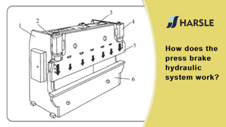
Welded plate,high rigidity,is support at eccentric socket(9),by left and right cylinders and stroke cylinder drive,finish cutting by pendulum repeat.(see Fig.1)
The vertical surface of up-cut support is curve, keep the gap between up-cut and low-cut coincidence.
Pressure device(hold down)
It is consisted of some pressure feed cylinders installed at support board in front of machine frame. Oil flow in pressure feed cylinder, pressure head press down against the pull force of strss spring(18),press plate tightly. Finish cutting, the cylinders are reset by the pull force of stress spring. The pressure is bigger as thicker as the thickness of plate.(See Fig.3)
Front gauge and back gauge
Front gauge:fixed on worktable,valve display on ruler, adjust mobile bar to necessity valve. When cut thin steel plate, cut it conveniently on front gauge.
Back gauge (see picture5) fixed on up-cut board, pendulum up and down as up-cut board. Adjust back gauge by 0.55kw motor,reduce through gear, and drive by control rod. Brake down the button”+”(or”_”),can adjust gauge to front or back. When mechanic adjustment cannot get the necessity valve,turn hand-wheel(50) to demand valve,the adjustment of back gauge is convenient and reliability.
The standard range of back gauge is 20-750mm. When the length of cutting plate is longer than the max distance of back gauge, remove the back gauge(43) to the least place, lift up the board by the incline surface of support frame(47),then can cut any length of plate.(see fig.4)


Installation of hydraulic shearing machine
Packing/shipment of hydraulic shearing machine
All machines leaving the factory are packed with squaring arm and foot panel tied to the hand guard. Working tools and operation manual are packed into one box.
All exposed surfaces of the machine are coated with rust guard,easily removable by kerosene or solvent.
Lifting the hydraulic shearing machine
Use only approved and safe wire rope to lift this machine from two lifting point which is located at both side frame of the machine.(see.fig.5)

Foundation
All our shears are designed to use the foundation, details please check the attached foundation drawing.
Installation
This hydraulic shearing machine must be properly leveled to give a good cut. Leveling is done by putting a good leveling gauge at the plate hold down area. Always pre-prepare five pieces of base plate(dimension 150*150*9mm),below machine footing to prevent leveling screw from digging into the concrete floor.
On completion of leveling, a cement grout mixture must be packed under and around the feet to maintain correct leveled position.
Electrical installation
Be sure that the local power supply is suitable for this hydraulic shearing machine before any electrical power up. Connect power cable to the bottom left of the electrical panel.
Some machine may require N(Neutral) wire.
Electrical diagram of hydraulic shearing machine

4.1 The following steps are to be cared for by the owner and must be carried out by specialized personnel.
Check the hydraulic shearing machine nameplate and confirm that the wiring of the machine
Corresponds to the available power in your facility.
If the required power does not meet the requirement of the machine please contact your electrical supplier.
The power incoming to the machine should be fused so that the machine can be fully disconnected for repair.
The electric drawings check the following attachments, the different controller has different drawings.
4.2All the operating buttons fixed on controller panel at front except foot switch SF. The symbol of each function is displayed on the above of buttons.
Detail operation steps of the digial display system as follows:
Open the door of the electric box, close the power switch QF1,QF2,the machine is wiring on , close the electric box. Push the key button SA1,SWITCH ON THE CONTROL CIRCUIT. Indicating light HL1 lighting shows the machine power on.
Push button SB4 or SB5 ,can run the back gauge to the front or go back. The position of back gauge displayed on the SICK mechanical display,at the max. And min. Travel of back gauge, installed limit switches(SQ3,SQ4),standard max. Travel is 500m-700mm;min travel is 20mm.
Push lighting button SB3,lighting shows the pump motor start to work, at the same time, you can hear the working voice.Switch the button SA3, select cutting mode. At , it is manual mode. At, it is auto mode.
Is the illumination light, turn SA4 to (1),start to count, To(0) place, stop counting.

 English
 Pусский