محاولة إتقان DELEM DA-69T مكابح الضغطسيساعدك هذا الدليل على فهم خطوات التشغيل لضمان الانحناء الدقيق وتحسين الإنتاجية.
ديليم DA-69T مكابح الضغط يوفر ميزات تحكم متقدمة لثني دقيق. تعرّف على التعليمات خطوة بخطوة لتشغيله الأمثل وكيفية تجنب الأخطاء الشائعة التي تعيق الإنتاجية.
الآن، دعنا نستكشف عملية الإعداد والميزات الرئيسية لتحسين مكبس الثني DELEM DA-69T الخاص بك للعمليات السلسة.
نظرة عامة على التشغيل والمقدمة العامة
1. وحدة التحكم
يبدو التحكم على النحو التالي:

قد يختلف المظهر الدقيق لعنصر التحكم الخاص بك.
يتم تشغيل وحدة التحكم بشكل رئيسي عبر شاشة اللمس. ستجد وصفًا للوظائف وأدوات التحكم باللمس المتاحة في الأقسام التالية من هذا الدليل، بالإضافة إلى وصف الوظائف المحددة.
بجانب عناصر التحكم باللمس، يتكون الجزء الأمامي من عنصر التحكم من زر التوقف في حالات الطوارئ، وعجلة اليد، وأزرار البدء والإيقاف.
تحتوي مفاتيح الوظائف الخاصة، والتي يمكن تركيبها في اللوحة العلوية للتحكم، على وصف محدد لها بالتوازي مع دليل المستخدم هذا وسيتم توفيرها من قبل الشركة المصنعة للجهاز.
يركز دليل المستخدم هذا على برنامج التحكم ووظائف الماكينة ذات الصلة.
2. عناصر التحكم الأمامية
تتكون اللوحة الأمامية، بجانب الشاشة، من عناصر التحكم التالية:

3. موصلات USB

4. أوضاع التشغيل والبرمجة
تبدو الشاشة الرئيسية للتحكم على النحو التالي:
تختلف الشاشة باختلاف زر التنقل النشط. ستظهر الشاشة الرئيسية أعلاه مع تفعيل وظيفة المنتجات.
بمجرد النقر على الأوضاع المختلفة، سيتم تحديد الوضع المحدد.
هيكل الشاشة الرئيسية هو كما يلي:
لوحة العنوان
تظهر لوحة العنوان دائمًا في الأعلى. في هذه المنطقة، يمكنك العثور على معلومات الشعار، والمنتج المُحمّل، ودليل المنتجات المحددة، وصف الخدمة (عند تفعيله). كما يمكنك العثور على مؤشرات الجهاز هنا.

لوحة المعلومات
في لوحة المعلومات، يتم عرض جميع الوظائف والتصورات المتعلقة بالوضع المحدد ويمكن العثور عليها.

لوحة الأوامر
تعتبر لوحة الأوامر جزءًا من لوحة المعلومات وهي الموقع الذي يمكن العثور فيه على عناصر التحكم المتعلقة بلوحة المعلومات.
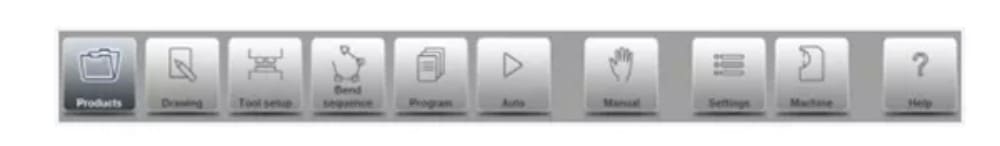
لوحة التنقل
لوحة التنقل هي المنطقة التي تضم جميع الأوضاع الرئيسية. هذه المنطقة مرئية دائمًا. يمكن استخدام عناصر التحكم، وهي أزرار كبيرة مزودة بأيقونات، للتبديل مباشرةً من وضع إلى آخر.

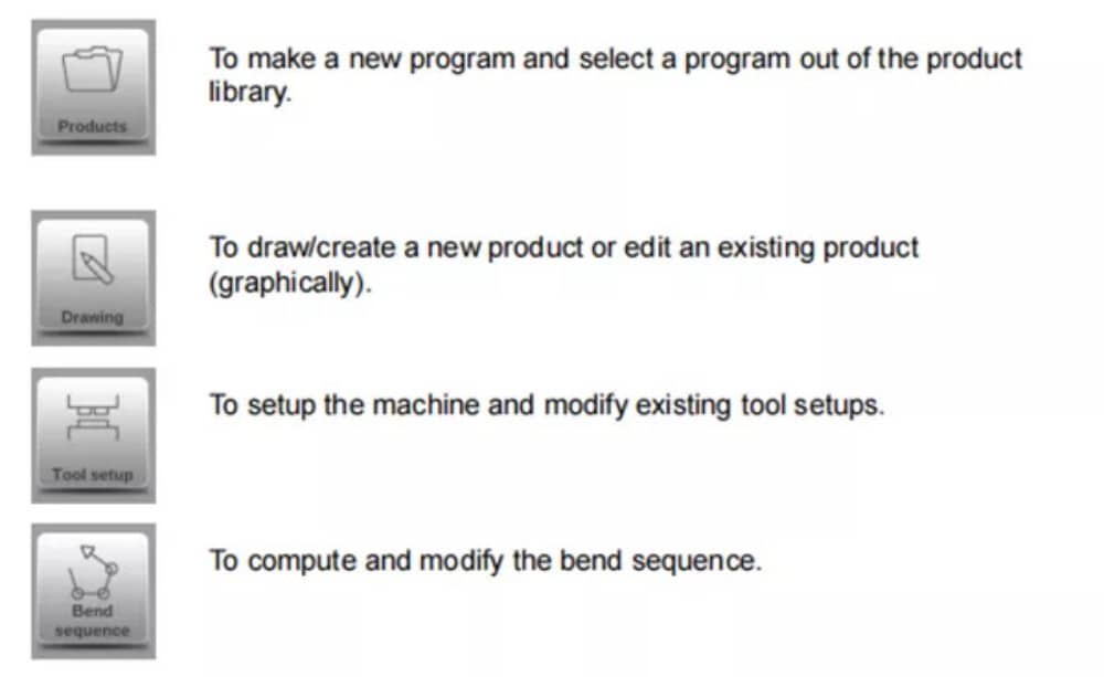
شرح الأوضاع الرئيسية / أزرار التنقل

5. البدء
(1)مقدمة
للحصول على برنامج ثني لمنتج، يُتيح عنصر التحكم إمكانية إنشاء رسم للمنتج وحساب تسلسل ثني صحيح له. باستخدام هذه المعلومات، يُنشأ برنامج ثني للمنتج.
يتم ذلك من خلال الخطوات التالية:
● انتقل إلى وضع المنتجات في لوحة التنقل وابدأ منتجًا جديدًا بالنقر فوق منتج جديد.
● أدخل خصائص المنتج وابدأ برسم ملف تعريف المنتج ثنائي الأبعاد في وضع الرسم.
● التحقق من الأدوات، وتعديلها أو إنشاء إعداد جديد في وضع إعداد الأداة.
● استخدم وضع تسلسل الانحناء لتحديد تسلسل الانحناء عن طريق حسابه أو تعديله يدويًا بناءً على فكرتك الخاصة.
● عند الحاجة، قم بتعديل برنامج CNC الرقمي عبر وضع البرنامج.
● اضغط على "تلقائي" ثم اضغط على زر "ابدأ" لإنتاج المنتج المبرمج.
(2) الاستعدادات
قبل البدء في برمجة المنتج، لا بد من إجراء التحضيرات التالية.
● يجب برمجة خصائص المواد الصحيحة في مكتبة المواد. يمكنك العثور على هذه المعلومات في صفحة المواد ضمن وضع الإعدادات.
● يجب برمجة الأدوات الصحيحة في مكتبة الأدوات. الأدوات ضرورية لإنشاء برنامج CNC. يمكنك العثور على مكتبات أنواع الأدوات المختلفة في وضع الآلة.
(3) إنشاء رسم
يتيح لك هذا التحكم إنشاء رسم للمنتج المطلوب. باستخدام هذا التطبيق، انقر على "رسم" في لوحة التنقل، ليتم إنشاء رسم ثنائي الأبعاد أو ثلاثي الأبعاد للمنتج. في هذه المرحلة، لا حاجة لحساب الانحناءات أو الأبعاد: يمكنك إنشاء أي رسم أو رسم. تعتمد طريقة الرسم على شاشة اللمس على:
● رسم تخطيطي
● إعداد القيمة
رسم تخطيطي
يمكن رسم شكل المنتج والأداة بالنقر على الشاشة في مختلف الاتجاهات. سيتبع التطبيق النقر برسم خط بين النقاط المحددة. ستظهر النقطة الأخيرة من التصميم دائمًا بنقطة حمراء كبيرة.
عندما تظهر نقطة الرسم على الشاشة، يمكنك تثبيت إصبعك على هذا الموضع وتحريكه عبر الشاشة لتحريك الخط المتصل في الاتجاه المطلوب أو زيادة طوله. تُعرف هذه الطريقة باسم "السحب". ستظهر قيمة الطول والزاوية على الشاشة، ويمكن تعديلها لتكون دقيقة أو قريبة من القيمة المطلوبة.
تحديد القيمة
بمجرد رسم المنتج أو الأداة بطريقة الرسم التخطيطي، يُمكن تحسين القيم الدقيقة لأطوال الخطوط وزواياها باستخدام طريقة ضبط القيمة. ما عليك سوى النقر مرتين على قيمة طول الخط أو الزاوية لتغييرها، وستظهر لوحة المفاتيح. يُمكن إدخال القيمة بطريقتين.
من التأكيد:
● أدخل الوظيفة
● وظيفة الإدخال التالي
تُغلق دالة الإدخال لوحة المفاتيح بعد إدخال القيمة. أما دالة الإدخال-التالي، فتُدخل القيمة على الخط أو الزاوية المراد تغييرها، وتبقى لوحة المفاتيح مفتوحة لخطوة البرمجة التالية.
في حالة أن القيمة المكتوبة خاطئة، يمكن الضغط على زر "التراجع" الموجود مباشرة في حقل الإدخال للعودة إلى القيمة الأصلية أو مفتاح المسافة الخلفية على لوحة المفاتيح لحذف آخر حرف مكتوب.
وظيفة التكبير
بالضغط على الشاشة بإصبعين في آنٍ واحد، يُمكن تكبير وتصغير الرسم أو الأداة أو عرض الآلة. بفرد الأصابع، يُكبّر النظام الصورة، وبتقريب الأصابع، يُصغّرها.
ملائمة للشاشة
ستجد في أيقونات الأوامر على جانب الشاشة وظيفة "ملاءمة الشاشة". يمكنك استخدامها عندما لا يكون حجم الرسم واضحًا في الصورة. ما عليك سوى النقر مرة واحدة، وسيُصبح حجم الرسم كاملًا ليناسب شاشة الرسم.
التنقيب
بلمس إصبعين متزامنين وسحبهما على الشاشة (مع تحريكهما في نفس الاتجاه)، يُمكن تحريك الكائن في عرض ثلاثي الأبعاد. في العرض ثنائي الأبعاد، يُتيح إصبع واحد التحريك أيضًا.
الدوران
في تقنية ثلاثية الأبعاد، يمكن تدوير المنتج أو الأداة أو التصور الميكانيكي من خلال تحريك إصبع واحد على الشاشة.
يمكن العثور على مزيد من المعلومات حول هذا الموضوع في الفصل الثالث.
مميزات أداة الرسم
● التصميم الجرافيكي لأشكال المنتجات ثنائية وثلاثية الأبعاد (إن وجد)
● سمك الورقة المقاسة
● التوسع التلقائي
● يمكن إدخال الأبعاد المتوقعة الأفقية والرأسية
● تصميم أداة بالمقياس الحقيقي
● أشكال مختلفة من الآلات (عوارض الضغط والطاولات)
● تغيير الأطوال والزوايا
● إضافة أو حذف الانحناءات
● يمكن تطبيق ميزات الانحناء الخاصة
● يمكن برمجة انحناءات الحاشية
● يمكن استخدام الانحناءات المتصادمة لنصف القطر الكبير
● يمكن نسخ المنتجات الموجودة وتغييرها وتخزينها كمنتج جديد
● اختيار البعد الختامي أو أعلى دقة للتسامح
● ربط البرامج ثنائية الأبعاد بالإنتاج ثلاثي الأبعاد
(4) تحديد تسلسل الانحناء
عند اكتمال رسم المنتج، يُتيح لك نظام التحكم وضع إعداد الأداة لبرمجة إعداد الأداة بدقة وفقًا لترتيبها على الآلة. بعد ذلك، يمكنك اختيار وضع تسلسل الانحناء لتحديد ومحاكاة تسلسل الانحناء المطلوب.
في وضع تسلسل الانحناء، يعرض عنصر التحكم المنتج والآلة والأدوات. في هذه القائمة، يمكن برمجة تسلسل الانحناء وفحصه بصريًا. عند تحديد تسلسل انحناء، يمكن إنشاء برنامج CNC.
يمكن العثور على مزيد من المعلومات حول هذا الموضوع في الفصلين الرابع والخامس.
حساب تسلسل الانحناء
• حساب تلقائي للحد الأدنى لوقت الإنتاج
• تحديد تسلسل الانحناء التفاعلي
• تحديد تسلسل الانحناء اليدوي
• تصور تصادم المنتج مع الأدوات والآلات
• اختيارات مجانية للأدوات وأشكال الآلات
• تعيين أوقات الدوران وسرعة المقياس الخلفي وما إلى ذلك.
• حساب طول الفراغ
• مؤشر وقت الإنتاج
• محاكاة تسلسل الانحناء
• أوضاع الأصابع القابلة للبرمجة
(5) البرنامج العددي
تتيح لك قائمة البرنامج الوصول إلى البرنامج الرقمي وقيم المنتج النشط.
هناك طريقتان لإنشاء برنامج CNC:
• أدخل برنامجًا رقميًا، يتم البدء به عبر وضع المنتجات، ثم انقر فوق برنامج جديد، خطوة بخطوة؛
• قم بإنشاء البرنامج من محاكاة الانحناء الرسومية التي بدأت عبر وضع المنتجات، ثم انقر فوق منتج جديد، عبر وضع الرسم. (انظر: وضع الرسم؛ رسم المنتج).
في حال إدخال البرنامج يدويًا، لا يوجد فحص تصادم. يجب إدخال جميع قيم البرنامج يدويًا. يعتمد البرنامج على خبرة المُشغّل.
إذا تم إنشاء البرنامج من تسلسل منحنى رسومي، فيمكن عرضه أثناء الإنتاج. ويمكن تعديل البرنامج المُنشأ وفقًا لاحتياجات التشغيل.
يمكنك العثور على مزيد من المعلومات حول هذا الموضوع في الفصل السادس.
عندما يتم الانتهاء من رسم مع تسلسل الانحناء، ويتم تخزين البرنامج، تتم معالجة البرنامج لاحقًا ويصبح البرنامج الرقمي متاحًا.
يقوم النظام بحساب :
• القوة اللازمة
• تعديلات الماكينة مثل:
• موضع المحور Y
• إزالة الضغط
• موضع المحور X
• سحب المحور X
• فتحة على شكل حرف Y
• محاور R
• محاور Z
يتم حساب مواضع المحاور وفقًا لتكوين الماكينة.
(6) القائمة التلقائية والقائمة اليدوية وأوضاع الإنتاج
يمكن تنفيذ برنامج المنتج عبر الوضع التلقائي. في الوضع التلقائي، يمكن تنفيذ البرنامج بالكامل ثنيةً تلو الأخرى. في الوضع التلقائي، يمكن اختيار وضع الخطوة لبدء كل ثنية على حدة.
الوضع اليدوي للتحكم هو وضع إنتاج مستقل. في هذا الوضع، يمكن برمجة انحناءة واحدة وتنفيذها. ويُستخدم عادةً لاختبار أداء نظام الانحناء.
يمكن العثور على مزيد من المعلومات حول هذا الموضوع في الفصلين 7 و 8.
(7) النسخ الاحتياطي للبيانات، التخزين الخارجي
يمكن تخزين ملفات المنتجات والأدوات خارجيًا. وحسب الإعدادات، يمكن تخزين هذه الملفات على شبكة أو على وحدة تخزين USB. يُسهّل هذا النسخ الاحتياطي للبيانات المهمة وتبادل الملفات بين وحدات تحكم Delem.
يمكنك العثور على مزيد من المعلومات حول هذا الموضوع في الفصل التاسع.
6. مساعدات البرمجة
(1) نص المساعدة
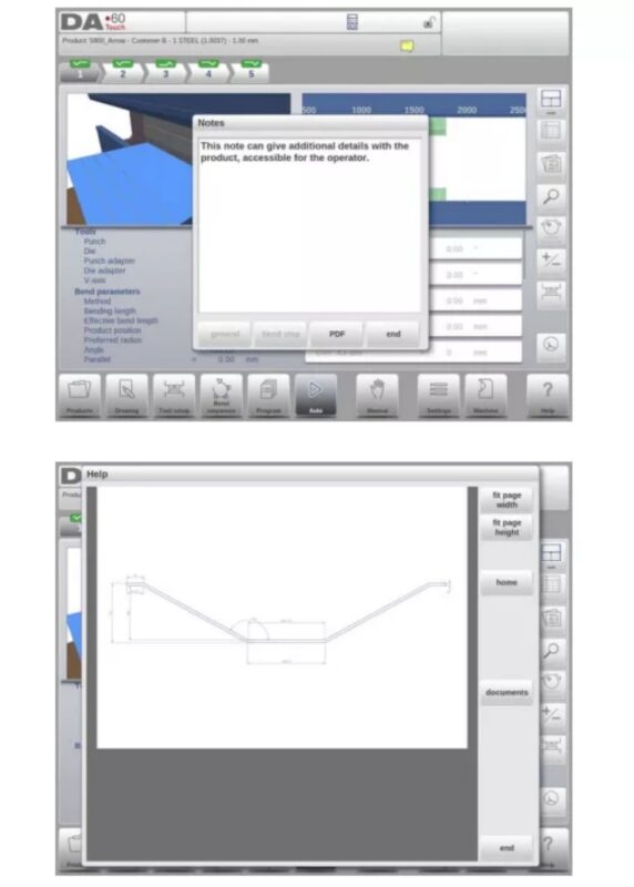
هذا العنصر مُجهّز بوظيفة مساعدة فورية. عند الضغط على زر المساعدة في لوحة التنقل، ستظهر مساعدة مُراعية للسياق.
لتنشيط نافذة المساعدة لمعلمة ما، انقر فوق زر المساعدة في لوحة التنقل.
تظهر نافذة منبثقة تحتوي على معلومات حول المعلمة النشطة.

تحتوي نافذة "المساعدة" هذه على نفس المعلومات الموجودة في دليل التشغيل.
يمكن استخدام نافذة المساعدة على النحو التالي:
يمكنك تصفح النص بتحريك إصبع واحد في الاتجاه المطلوب. بالنقر على الجزء السفلي أو العلوي من الشاشة، يمكنك استخدام "الصفحة السابقة" أو "الصفحة التالية" لتصفح نص المساعدة.
تساعد وظيفة الفهرس على الانتقال مباشرةً إلى جدول المحتويات. تساعد الروابط التشعبية في الجدول على الوصول مباشرةً إلى الموضوع المطلوب.
اضغط على "إنهاء" لإغلاق نافذة "المساعدة".
(2) وظيفة القائمة المربعة
تحتوي العديد من معلمات وحدة التحكم على عدد محدود من القيم الممكنة. عند تحديد هذه المعلمة، بالنقر على خط المعلمة على الشاشة، ستظهر قائمة الخيارات بالقرب من موضع النقر، ويمكنك اختيار القيمة المطلوبة.

للتراجع عن التحديد وقائمة المربع المفتوحة، فإن النقر خارج المربع سيؤدي إلى إغلاقه دون تغيير المعلمة المحددة.
(3) الفلترة، البحث المباشر، الفلترة التلقائية
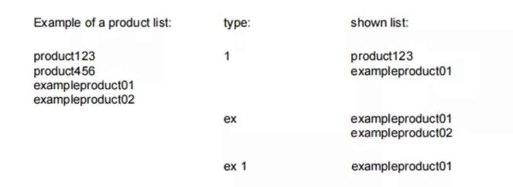
في بعض الأوضاع، تُعرض قائمة بالكيانات (المنتجات، الأدوات، المواد، إلخ). ومن أمثلة هذه القوائم وضع "المنتجات" (اختيار المنتج). للبحث عن منتج أو أداة معينة، يمكن استخدام خاصية التصفية. اضغط على زر الأمر "تصفية"، واكتب جزءًا من المعرف في حقل الإدخال. تلقائيًا، تقتصر القائمة على العناصر التي تحتوي على الجزء المكتوب.
يمكن فصل أجزاء البحث المتعددة عن طريق .
لإغلاق شاشة الفلتر المفتوحة، استخدم زر الإغلاق الموجود على لوحة المفاتيح على الجانب الأيمن بجوار لوحة المفاتيح.
الفلتر التلقائي
بالإضافة إلى وظيفة التصفية، تحتوي عناوين الأعمدة مثل جداول اختيار الأدوات وجدول اختيار المنتج على وظيفة "التصفية التلقائية".
عند النقر على رأس العمود، يُمكن فرز القائمة بناءً على ذلك العمود. يُظهر المثلث في الرأس كمؤشر على ترتيب الفرز.
عند النقر على رأس الصفحة مع خاصية التصفية التلقائية، ستظهر قائمة تلقائيًا تعرض خيارات التصفية المتاحة، بناءً على الإدخالات المتاحة في ذلك العمود. على سبيل المثال:
عند استخدام هذا الخيار لاختيار القالب، يُمكن تصفية فتحة V إلى القيمة المطلوبة. ستعرض القائمة فقط القوالب التي تتوافق مع الفلتر المُحدد.
يمكن إلغاء الفلاتر بنفس الطريقة. كما توفر القائمة إمكانية إزالة الفلاتر.

(4) الملاحة
في بعض الأوضاع، يتم تقسيم شاشات البرنامج إلى علامات تبويب.
يمكن تحديد علامات التبويب بسهولة بمجرد النقر عليها. عندما لا تكون علامة تبويب ظاهرة تمامًا أو غير ظاهرة على الإطلاق، فبمجرد سحب صف علامات التبويب أفقيًا، يمكن "سحب" علامة التبويب المطلوبة وتحديدها.
(5) إدخال النص وتحريره
يمكن استخدام المؤشر لإدخال قيمة أو نص محدد ضمن مُدخل موجود. ما عليك سوى النقر على الموضع المطلوب. سيظهر المؤشر، وستتم إضافة المُدخلات إليه.
على سبيل المثال، في "تحرير الملاحظات"، حيث يُمكن إدخال أسطر متعددة، يُستخدم زر الإدخال لتغذية الأسطر. تتوفر خيارات القص والنسخ واللصق على لوحة المفاتيح لتسهيل التحرير. كما يُمكن استخدام التراجع والإعادة داخل هذا المحرر.

يمكن إظهار لوحة المفاتيح أو إخفاؤها في محرر متعدد الأسطر هذا باستخدام مفتاح السهم الموجود في الزاوية اليسرى السفلية.
(6) كتابة الأحرف الأبجدية الرقمية مقابل الأحرف الخاصة
يمكن استخدام كلٍّ من الأحرف الأبجدية الرقمية والأحرف الخاصة في جميع أنحاء عنصر التحكم. ستظهر لوحة مفاتيح أبجدية رقمية كاملة على الشاشة عند الحاجة.
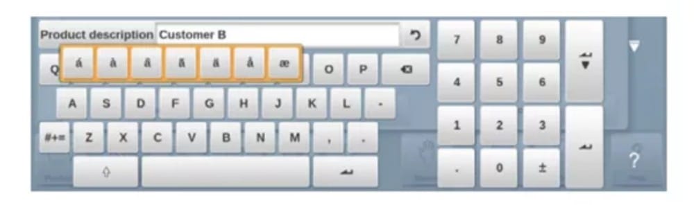
عند تحرير حقل رقمي بحت، ستظهر الأحرف الأبجدية الرقمية باللون الرمادي، ولا يُمكن استخدام سوى لوحة المفاتيح الرقمية. بالنسبة للحقول التي تُمكّن من استخدام سلاسل أبجدية رقمية، تكون لوحة المفاتيح متاحة بالكامل. يُمكن العثور على الأحرف الخاصة مثل ? % باستخدام زر الأحرف الخاصة في الجانب السفلي الأيسر من لوحة المفاتيح.
يتم دعم الأحرف الخاصة (مثل á، à، â، ã، ä، å، æ) بواسطة لوحة المفاتيح التي تظهر على الشاشة من خلال الضغط باستمرار على أحد الأحرف (مثل "a").
(7) الآلة الحاسبة
يوفر التحكم CNC "آلة حاسبة سطح مكتب" متاحة للمشغل.
في الجزء العلوي من الشاشة، يمكن استخدام رمز الآلة الحاسبة للتبديل إلى وظيفة الآلة الحاسبة.
توفر لوحة المفاتيح وظائف الآلة الحاسبة التي يمكن استخدامها بشكل مستقل. تتوفر وظائف قياسية (الجمع، الطرح، الضرب، القسمة)، بما في ذلك النسبة المئوية، والجذر التربيعي، والتربيع، ووظائف الذاكرة.
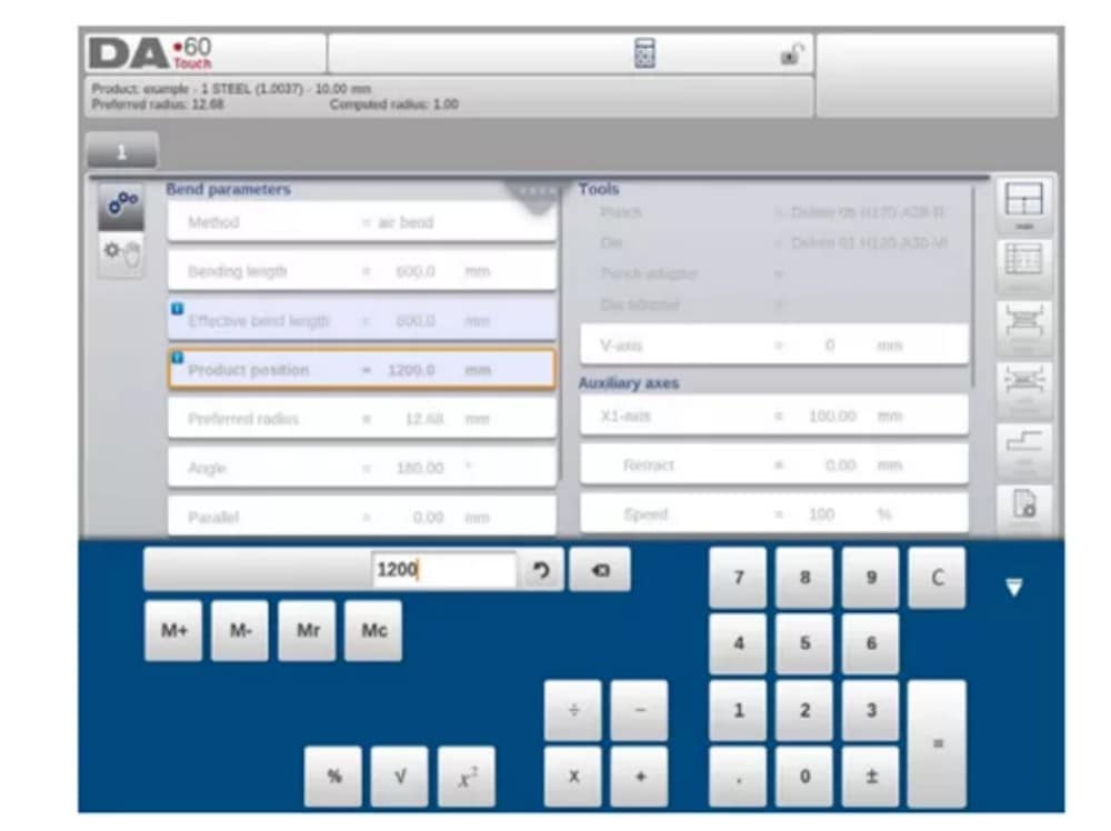
في حال استخدام قيم المعاملات كمدخلات والنتائج كمخرجات في الحسابات، يُمكن الانتقال إلى الآلة الحاسبة من مدخل المعاملات. سيؤدي هذا إلى نقل قيمة المعاملات إلى الآلة الحاسبة، والنتيجة إلى سطر الإدخال.
لا حاجة للقص أو اللصق. فقط عند إدخال القيمة المحسوبة وتأكيدها في سطر إدخال المعلمات، سيتم استخدامها لاحقًا.
(8) مركز الرسائل
عند عرض رسائل واردة من وحدة التحكم المنطقية القابلة للبرمجة (PLC)، أو أنظمة السلامة، أو وحدات LUAP، أو جهاز التسلسل، يُمكن إرسال هذه الرسائل إلى "مركز الرسائل". عند عرض رسالة في نفس الوقت، يظهر رمز مركز الرسائل في الصف العلوي من رأس الصفحة، بجوار رمزي الآلة الحاسبة وقفل المفاتيح، على سبيل المثال. عند النقر على رمز مركز الرسائل هذا، تُحذف الرسائل من الشاشة، مما يُتيح إمكانية البرمجة والتحرير العاديين.
عند النقر مرة أخرى، يتم عرض الرسائل الفعلية.
عندما تكون الرسائل في الخلفية، يحتوي رمز مركز الرسائل على مؤشر إضافي لإظهار الرسائل الواردة الجديدة التي لم يتم عرضها بعد.
(9) الشبكة
وحدة التحكم CNC مُجهزة بواجهة شبكة. تتيح وظيفة الشبكة للمشغلين إمكانية استيراد ملفات المنتج مباشرةً من مجلدات الشبكة أو تصدير ملفات المنتج النهائي إلى مجلد الشبكة المطلوب.
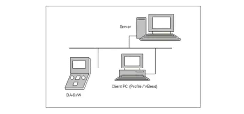
يحتوي الفصل 9 حول النسخ الاحتياطي/الاستعادة في وضع الإعدادات على مزيد من المعلومات حول إمكانيات الشبكات.
(10) وظيفة قفل المفاتيح
لمنع حدوث تغييرات في المنتجات أو البرامج، توفر وظيفة قفل المفاتيح إمكانية قفل عنصر التحكم.
هناك مستويان لقفل التحكم: قفل البرنامج وقفل الجهاز.
• في قفل البرنامج، لا يمكن تحديد سوى منتج وتنفيذه في الوضع التلقائي.
• في حالة قفل الماكينة، يتم قفل الماكينة ولا يمكن استخدام عنصر التحكم.
لقفل عنصر تحكم، انقر على رمز القفل أعلى الشاشة. بناءً على الرمز المستخدم، سيكون عنصر التحكم في وضع "قفل البرنامج" أو "قفل الجهاز". سيظهر قفل "قفل البرنامج" مغلقًا باللون الرمادي. أما قفل الجهاز، فسيظهر القفل نفسه ولكن باللون الأحمر.
(11) لوحة وظيفة OEM
اعتمادًا على تنفيذ الشركة المصنعة للآلة، يمكن استخدام الزاوية اليمنى العليا من الشاشة للمؤشرات الخاصة.
للوصول إلى الوظائف المتعلقة بتلك المؤشرات، يمكن فتح لوحة وظائف OEM من خلال النقر على هذه الزاوية من الشاشة.
(12) إصدارات البرامج
يتم عرض إصدار البرنامج الموجود تحت سيطرتك في علامة التبويب "معلومات النظام" في قائمة "الجهاز".

المنتجات، مكتبة المنتجات
1. المقدمة

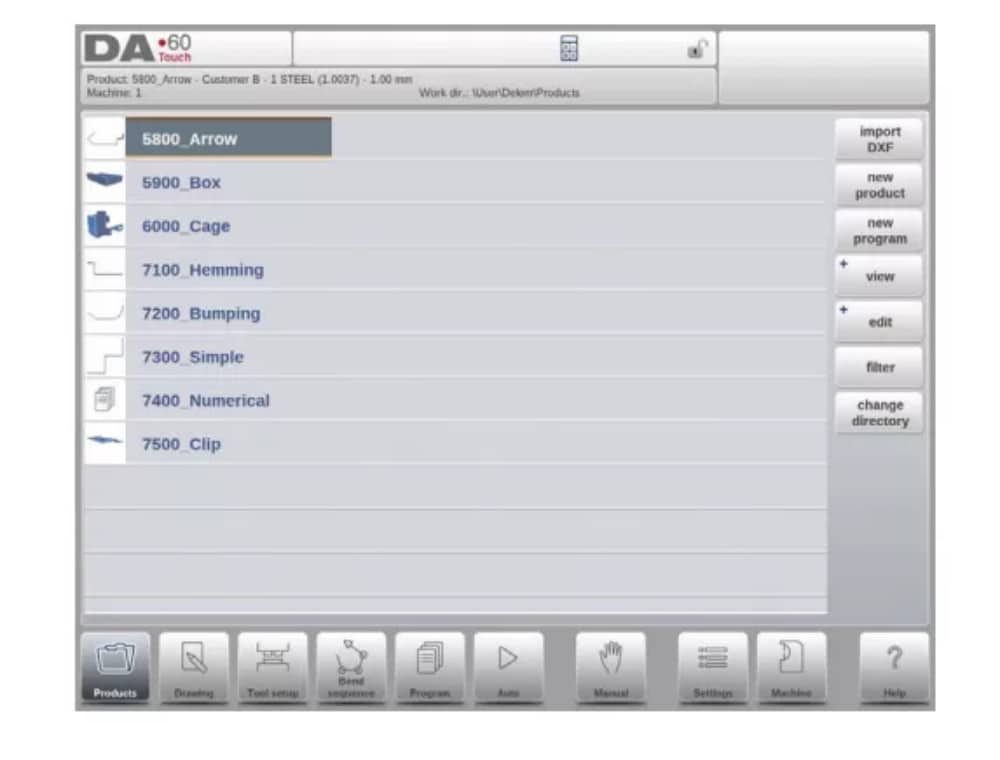
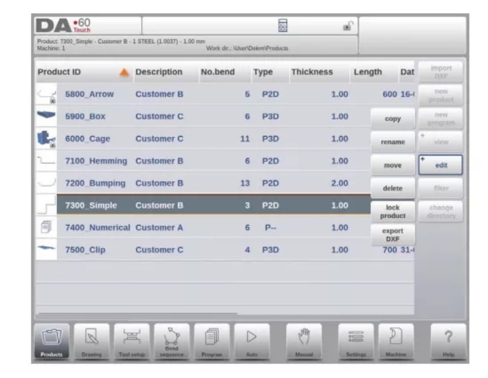
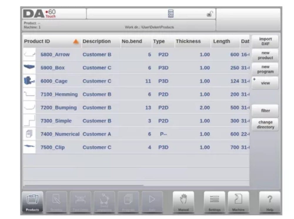
(1) المنظر الرئيسي

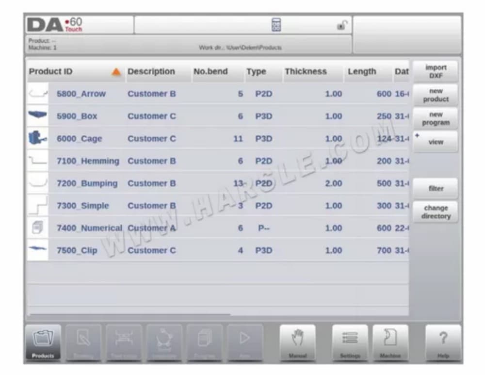
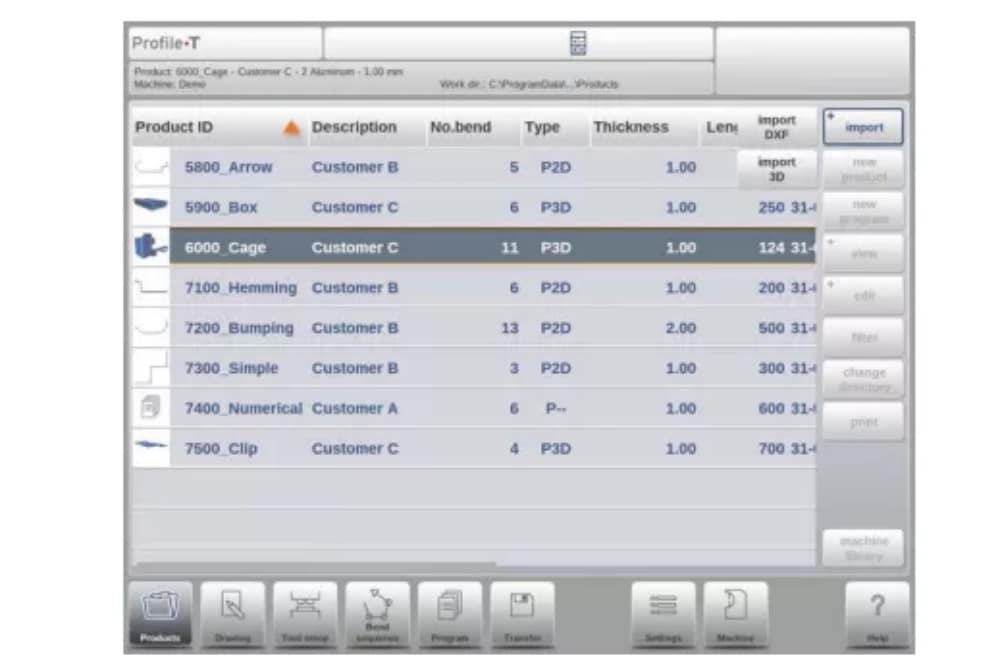
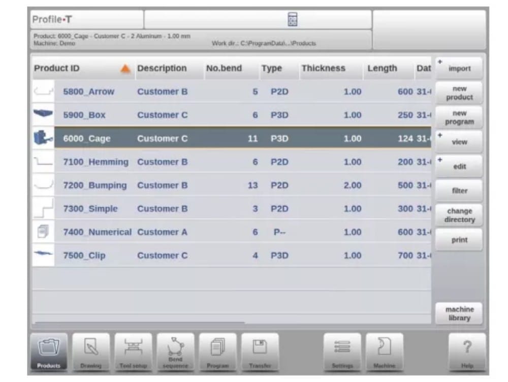
في وضع المنتجات، تُعرض نظرة عامة على مكتبة البرامج في وحدة التحكم. في هذا الوضع، يُمكن اختيار (تحميل) برنامج المنتج. بعد ذلك، يُمكن تعديل البرنامج أو تنفيذه.
يتكون كل عنصر في القائمة من صورة مصغرة للمنتج الرسومي (بالنسبة للبرامج الرقمية يتم عرض رمز)، ومعرف المنتج، ووصف المنتج، وعدد الانحناءات في المنتج، ونوع المنتج (النوع) وتاريخ آخر استخدام أو تعديل له.
يشير نوع المنتج إلى أنواع المنتجات التالية:
(2) اختيار المنتج
لاختيار منتج، يكفي ضغطة واحدة. سيتم اختيار المنتج وتحميله في الذاكرة. من هنا، يمكن بدء الإنتاج بالضغط على "تلقائي". كما يمكن بدء التنقل عبر رسم المنتج (إن وجد)، وإعدادات الأدوات، وتسلسل الانحناء، والبرنامج الرقمي للمنتج.

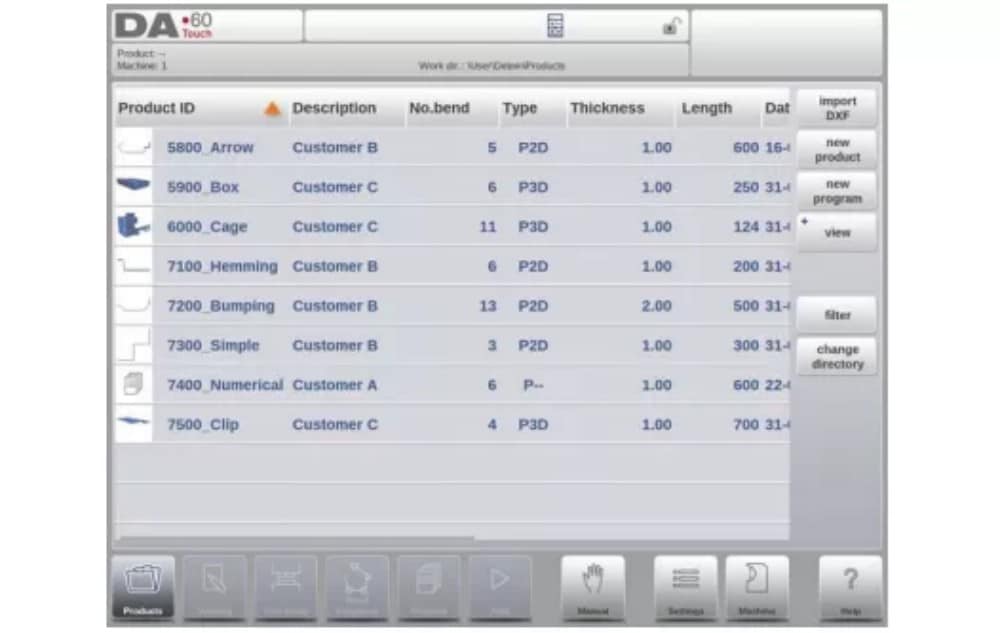
(3) منتج جديد، بدء منتج رسومي جديد
لبدء منتج رسومي جديد، انقر فوق منتج جديد.
بعد اختيار منتج جديد، تبدأ برمجة المنتج الجديد بتفاصيله العامة مثل معرف المنتج والسمك والمادة.

(4) برنامج جديد، بدء برنامج عددي
لبدء برنامج رقمي جديد، انقر فوق برنامج جديد.
بعد اختيار البرنامج الجديد، تبدأ البرمجة بتفاصيله العامة مثل معرف المنتج والسمك والمادة.

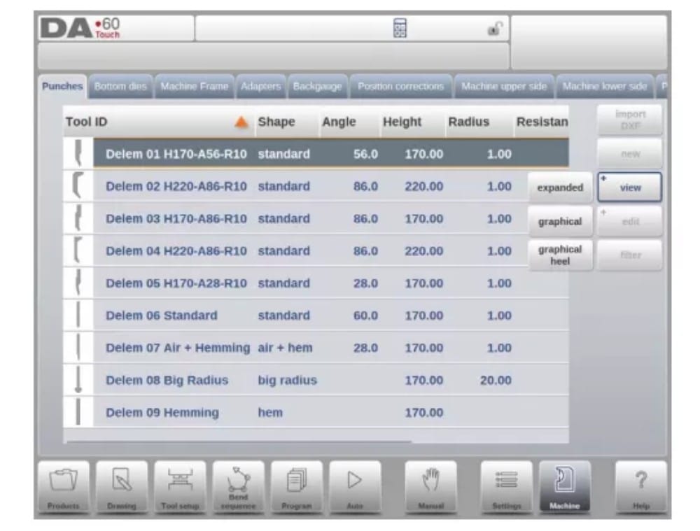
(5) المشاهدات
لعرض المنتجات على شكل قائمة بسيطة أو رسومية بالكامل، يمكن استخدام وظيفة العرض.
من خلال النقر على "عرض"، يمكنك تحديد أحد أوضاع العرض الثلاثة.

(6) تحرير ونسخ وحذف منتج أو برنامج
لحذف منتج في وضع "المنتجات"، حدده بالنقر عليه. سيتم تحديده.
بعد ذلك، انقر على "تعديل" ثم "حذف". لحذفه نهائيًا، أكّد السؤال. لحذف جميع المنتجات والبرامج دفعةً واحدة، انقر على "حذف الكل".

لنسخ منتج، حدد المنتج أو البرنامج المطلوب، ثم انقر على "تحرير" ثم "نسخ". بعد ذلك، يُمكنك برمجة اسم المنتج، وستتم عملية النسخ. سيظهر المنتج في نفس المجلد. ستكون النسخة المنسوخة مطابقة تمامًا، بما في ذلك إعدادات الأداة وتسلسل الثني إن وُجد.

(7) إعادة تسمية المنتج ونقله
يمكن أيضًا نقل المنتجات وإعادة تسميتها. ويمكن القيام بذلك في خطوة واحدة: النقل ينقل المنتج إلى دليل جديد، إعادة التسمية تسمح للمستخدم بإعطائه اسمًا جديدًا داخل نفس الدليل.
لنقل منتج أو إعادة تسميته، حدد المنتج أو البرنامج، ثم انقر على "تحرير"، ثم اختر "نقل" أو "إعادة تسمية" من القائمة. لإعادة التسمية، يمكنك اختيار اسم جديد. سيظهر المنتج في نفس المجلد. للنقل، يمكنك اختيار موقع جديد. سيكون المنتج المنسوخ نسخة طبق الأصل، بما في ذلك إعدادات الأدوات وتسلسل الانحناء إن وُجد.
(8) قفل/فتح المنتج
توفر وظيفة قفل/فتح المنتج طريقة بسيطة لمنع التغييرات غير المقصودة في البرامج أو المنتجات النهائية. بهذه الطريقة، لا يمكن تغيير المنتجات التي تم ضبطها وثبتت جودتها إلا بعد فتح قفل المنتج.
عند النقر على تحرير، يمكن التبديل بين ميزة قفل المنتج / إلغاء قفل المنتج لكل منتج أو برنامج.
(9) وظيفة التصفية
لتسهيل العثور على المنتجات، تعمل وظيفة التصفية على تمكين عمليات البحث المباشرة من خلال وضع المنتجات.
عند النقر على "تصفية"، ستظهر شاشة التصفية. بكتابة سلسلة التصفية المطلوبة، مع فصلها بمسافات اختيارية، سيبدأ البحث المباشر.
اختياريًا، يمكنك اختيار عرض مختلف. كما يمكنك تغيير الخاصية التي يُطبّق عليها الفلتر باستخدام "التحديد".
يمكن إجراء التحديدات على معرف المنتج، أو وصف المنتج، أو النوع، أو السُمك، أو الطول، أو التاريخ.
يمكنك إدخال اسم كامل أو رقم، أو جزء منه فقط. إذا أدخلت جزءًا من اسم، وكان هذا الجزء موجودًا في عدة أسماء منتجات، فسيعرض عنصر التحكم جميع أسماء المنتجات التي تحتوي على هذا الجزء. كما يمكنك إدخال اسم ورقم معًا.
انظر أيضًا القسم 1.6.3 حول التصفية و"البحث المباشر".

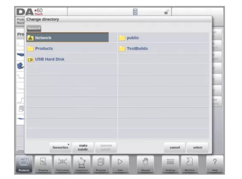
(10) تغيير الدليل
للانتقال إلى دليل منتج مختلف، أو لإضافة دليل منتج جديد، انقر على "تغيير الدليل". عند الحاجة إلى إزالة دليل قديم، حدد الدليل وانقر على "إزالة".
الدليل. عند الوصول إلى الدليل المطلوب، انقر على "تحديد" للعودة إلى شاشة المنتجات التي تعرض جميع المنتجات في الدليل. يظهر اسم الدليل المحلي النشط في رأس الصفحة.

(11) اختيار منتج الشبكة
عند تثبيت دليل شبكة في وحدة التحكم، يُمكن العثور على هذا الدليل المُثبّت ضمن "الشبكة". يتوفر "الشبكة" بجوار دليل المنتج عند استخدام دليل التغيير. يشير اسم محرك الأقراص المُثبّت إلى إمكانية اختيار المنتج.
تخزين.
يمكن تصفح أدلة الشبكة عبر متصفح الأدلة. يمكن تحديد الأدلة وإضافتها وإزالتها، بالإضافة إلى اختيار المنتجات. عند الوصول إلى الدليل المطلوب، انقر على "تحديد" للعودة إلى شاشة "المنتجات" التي تعرض جميع المنتجات في الدليل. أصبح دليل الشبكة الآن الدليل المحلي النشط، ويظهر اسمه في أعلى الشاشة.
عندما تغادر قائمة اختيار المنتج، يتذكر عنصر التحكم الدليل الفرعي النشط والمنتج النشط (إذا تم تحديد منتج) حتى يتم تحديد دليل أو منتج آخر.
عند العمل على شبكة "للقراءة فقط"، أو عند انقطاع اتصال الشبكة، سيتم حفظ المنتج في المجلد الفرعي "Recovered". يمكنك العثور على هذا المجلد الفرعي ضمن "المنتجات".
من خلال النقر على زر التحديث (في العرض) في وضع المنتجات، يتم تحديث مكتبة المنتج المعروضة على الشاشة، وهو أمر قد يكون مفيدًا عند العمل من موقع شبكة.
2. خيار استيراد DXF
كبديل لرسم المنتج المطلوب في عنصر التحكم، يُمكن لعنصر التحكم أيضًا استيراد ملف إخراج خارجي من نظام CAD. سيشرح هذا الفصل استخدام مُحوّل DXF لاستيراد ملفات DXF ووظائفه.
يبدأ خيار استيراد DXF بزر الأمر أعلى "منتج جديد". يفتح خيار استيراد DXF متصفح اختيار الملفات لتحديد ملف DXF.
يمكن العثور على الملفات على ذاكرة USB أو على مجلد الشبكة. يمكنك الوصول إلى الموقع المطلوب واختيار الملف.
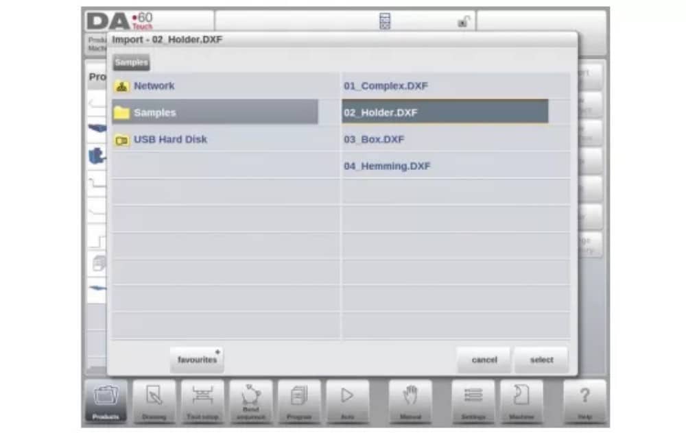
لاستيراد ملف DXF، يُنصح بإنشاء الرسم الأصلي بأقصى دقة ممكنة. يجب ربط خطوط الانحناء بخطوط الكنتور للحصول على رسم دقيق للمنتج. إذا لم يكن الأمر كذلك، يُمكن لمُحوّل DXF تصحيح الأخطاء البسيطة.
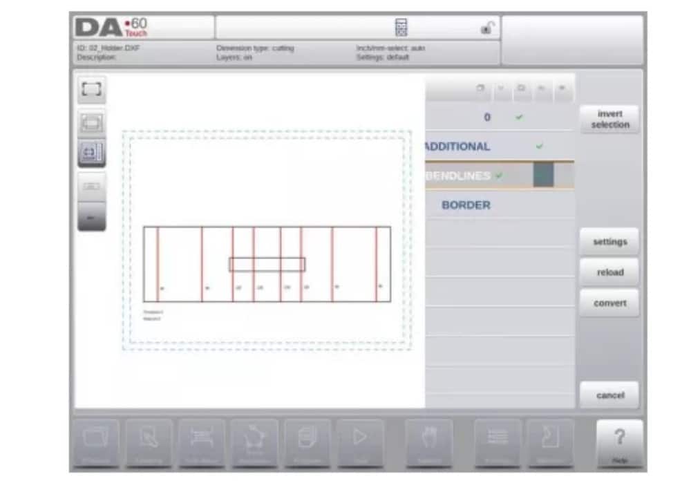
بعد تحديد ملف DXF، ستُفتح نافذة استيراد DXF لعرض ملف DXF. في حال تفعيل تحديد الطبقات، سيظهر الرسم متقطعًا، نظرًا لعدم وجود خط واضح لدلالته.
(1) أبعاد رسم المنتج
يمكن تنظيم ملف الرسم بطريقتين:
• أبعاد الإسقاط؛
• أبعاد القطع.
ويتم وصف هذه الطرق في الفقرات الفرعية التالية.
أثناء تشغيل مُحوِّل DXF، يُمكن التبديل بين أبعاد القطع وأبعاد الإسقاط. يُمكن القيام بذلك في إعدادات تحويل DXF.
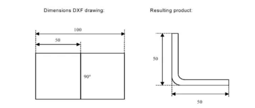
أبعاد الإسقاط
في هذه الحالة، تكون جميع جوانب المنتج وخطوط الانحناء مساويةً لطول المنتج الناتج. لا يُمثل الرسم الحجم الحقيقي للورقة المراد ثنيها، بل هو مجرد تمثيل لكيفية تنظيم الورقة في انحناءات وأسطح. عند حدوث ذلك،
بعد تحميل الرسم وتحويله، يُنشئ المُحوِّل رسمًا للمنتج بنفس أبعاد الرسم الأصلي تمامًا. لاحقًا، تُضاف معلومات إضافية حول المادة وسمك الصفيحة وأبعاد المنتج. يُترك لوحدة التحكم إنشاء برنامج CNC بمواضع المحاور المناسبة، مما يُنتج المنتج بالشكل المطلوب.
(2) خطوط الانحناء واختيار الطبقة مع تعيين الخط
للحصول على تحويل صحيح، يعد تعيين خصائص المنتج المحددة للخطوط في DXF أمرًا مهمًا.
بناءً على محتوى ملف DXF، يُمكن تخصيص خطوط الانحناء والمحيط ومعلومات النص الإضافية طبقةً تلو الأخرى. في حال تفعيل تحديد الطبقة، يتم البحث عن خطوط الانحناء تلقائيًا.
معلومات خط الانحناء
باستخدام خطوط الانحناء، يُمكن تحديد معلومات الزاوية عبر نص بجوار الخط. تسميات النص،
يمكن تكوينه في Settings::Labels، ويمكن استخدامه كما يلي:
• افتراضيًا: انحناء الهواء الطبيعي بقيمة موجبة أو سالبة
• الحاشية: حرف H متبوعًا بقيمة موجبة أو سالبة لزاوية ما قبل الانحناء.
• نصف القطر: R متبوعًا بقيمة نصف القطر.
تعريف:
• قيمة موجبة: ينحني الحافة لأعلى،
• قيمة سلبية: ينحني الحافة إلى الأسفل.
معلومات المنتج
إلى جانب رسم المنتج الفعلي، قد يحتوي رسم DXF على معلومات أخرى، مثل اسم الشركة المصنعة، وخطوط الأبعاد، ووصف المنتج، وغيرها. إذا كانت هذه المعلومات مُرتبة في طبقات أخرى غير رسم المنتج، يُمكن تصفية هذه المعلومات باختيار طبقات مُحددة فقط للتحويل. وإلا، يُمكن حذف المعلومات غير الضرورية في برنامج التحويل قبل بدء تحويل الرسم.
اختيار الطبقة
اعتمادًا على إعدادات استيراد DXF، والتي يمكن إدخالها من الشاشة الرئيسية، يمكن ضبط اختيار الطبقة أو إيقاف تشغيله.
في حالة تفعيل تحديد الطبقة، يُمكن تبديل عرض قائمة خصائص الطبقة. تُتيح الأزرار في الزاوية العلوية اليسرى هذا الخيار. توضح الفقرات التالية الفرق بين:
تم تشغيل اختيار الطبقة وإيقاف تشغيل اختيار الطبقة.
(3) التحويل
عندما يتم تعيين المهام بشكل صحيح، يمكن تنفيذ التحويل عن طريق النقر فوق زر التحويل.
سيتم عرض معاينة التحويل عند وجود تحذيرات أو أخطاء.
أثناء التحويل، يُمثَّل رسم DXF بخطوط مثل خط الكنتور، وخط الانحناء، وخطوط الكنتور الداخلية. تشير الألوان إلى خصائص تحويل الخطوط. ستختلف ألوان خطوط رسم المنتج بعد التحويل، ولكل لون معناه الخاص.
• الأزرق: خط الكنتور، هذا الخط هو جزء من المحيط الخارجي للمنتج.
• الأحمر: خط الانحناء، هذا الخط هو خط الانحناء.
• الأخضر: الخط الداخلي، هذا الخط هو جزء من الخط الداخلي للمنتج.
• أسود: سيتم عرض النصوص المخصصة باللون الأسود.

(4) تحويل أبعاد القطع، مع معلومات بدل الانحناء
في المرحلة الأخيرة من تحويل ملف DXF بأبعاد القطع، يجب إعادة استخدام بدل الانحناء الذي تم استخدامه أثناء النشر في التحويل.
لذلك فإن تحويل أبعاد القطع سوف يستخدم دائمًا جدول بدل الانحناء للتحكم وسوف يتحقق ما إذا كانت معلومات بدل الانحناء متاحة لجميع الانحناءات.
في حال توفر مجموعة واحدة فقط من معلمات بدل الانحناء لكل انحناء، فسيتم استخدام هذه المعلمة. ستعرض نافذة بدل الانحناء المنبثق زوايا المنتج مع بدل الانحناء المُحدد. إذا كانت هناك مدخلات أخرى في الجدول صحيحة، فيجب اختيار خط بدل الانحناء المناسب. يُساعد نصف القطر المُفضّل والمحسوب في هذا الاختيار.
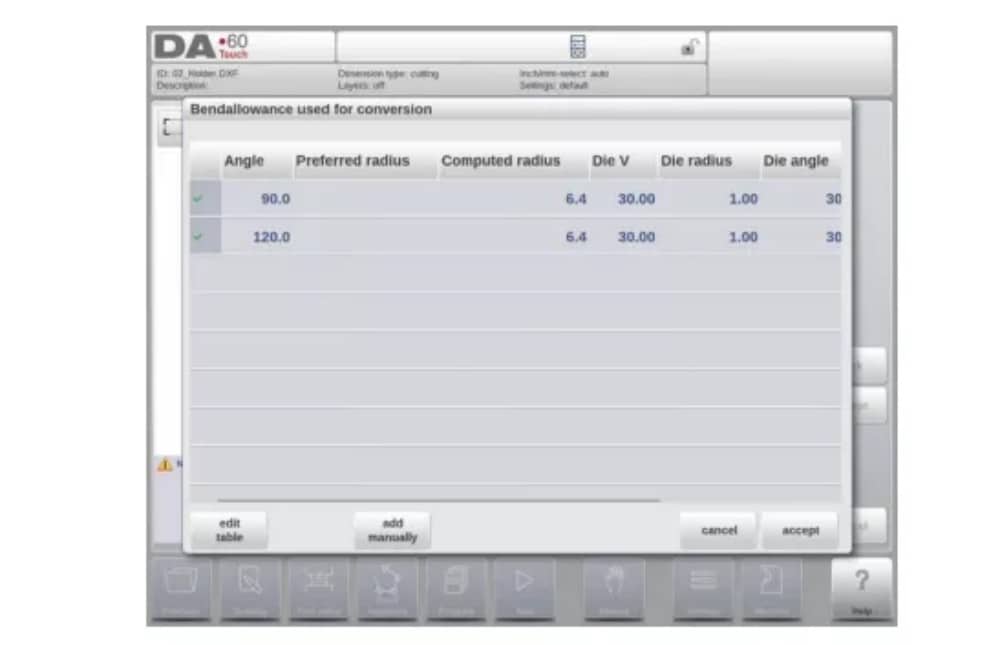
إضافة معلومات بدل الانحناء يدويًا
في حالة تقديم معلومات بدل الانحناء مع رسم أبعاد القطع DXF، المضمن في DXF أو كمعلومات منفصلة، فمن الممكن إدخال هذه المعلومات يدويًا.
عند استيراد ملف DXF وإضافة قيمة بدل الانحناء لكل انحناء (بناءً على معلومات خط الانحناء)، تُستورد هذه القيم وتُستخدم مع الانحناء المطلوب. سيستخدم عنصر التحكم هذا كمدخل للتحكم في حساب بدل الانحناء أو البحث في الجدول.
إذا تم إدخال هذه المعلومات أثناء تحويل DXF، فسوف يعمل هذا بشكل مكافئ، متجاوزًا حساب عناصر التحكم أو البحث في الجدول.
إذا لم تكن معلومات بدل الانحناء المطلوبة موجودة في الجدول، يُمكنك أيضًا إضافتها يدويًا قبل التحويل الفعلي. في حال عدم تحديد بدل الانحناء قبل أو أثناء تحويل DXF، فسيتم طلب ذلك تلقائيًا. يُمكنك اختيار إما الاختيار من بين الإدخالات الموجودة في جدول بدل الانحناء، أو إدخال بدل الانحناء لهذا التحويل فقط.
لتفعيل وظيفة برمجة معلومات بدل الانحناء في دالة الرسم (خاصية الانحناء) لعنصر التحكم، يجب تفعيلها في خصائص المنتج. يتم ذلك تلقائيًا عند الاستيراد.
(5) إعدادات DXF
في إعدادات محول DXF، يُمكنك ضبط معلمات التحويل. كما يُمكنك تخزين ملفات إعدادات متعددة لأنواع رسومات مُحددة. تتوفر وظيفتا الحفظ باسم والتحميل.
معلمات التحويل

3. وظيفة الاستيراد ثلاثي الأبعاد (ملف التعريف-T3D غير متصل بالإنترنت فقط)
كبديل لرسم المنتج المطلوب في التطبيق، يمكنك استيراد ملف نظام CAD مُنشأ خارجيًا. باستخدام وظيفة الاستيراد ثلاثي الأبعاد، يُمكن لبرنامج Profile-T3D استيراد ملفات .IGES و.STEP العامة.
سوف يشرح هذا الفصل استخدام وظيفة الاستيراد ثلاثي الأبعاد لملفات .IGES و.STEP.
(هذه الوظيفة متاحة حصريًا في Profile-T3D)
يتم تشغيل وظيفة استيراد الصور ثلاثية الأبعاد عبر زر "استيراد" أعلى "منتج جديد". يفتح "استيراد الصور ثلاثية الأبعاد" متصفحًا لاختيار ملف .IGES أو .STEP.
(1) التحويل

يمكن بدء التحويل بالضغط على "تحويل". سيبدأ هذا بترجمة التصميم ثلاثي الأبعاد إلى منتج ذي خطوط انحناء وخصائص خاصة بالصفائح المعدنية.
سيعرض التطبيق المنتج مع خطوط الانحناء المحددة.

في حالة عدم عثور المحول على أي عيوب، يتم معاينة التحويل ويمكنك إنهاء التحويل بالنقر فوق "قبول".
من هنا يتم تحويل المنتج وعرضه في وضع الرسم.
يمكنك الاستمرار في اختيار الأداة وبرمجة تسلسل الانحناء.

متطلبات ملف CAD ثلاثي الأبعاد
لاستيراد ملفات .IGES و.STEP، من الضروري استيفاء شروط تصميم منتجات الصفائح المعدنية. تتوفر الشروط عند الطلب لدى Delem.
يجب بالطبع إنشاء الملف ثلاثي الأبعاد المراد استيراده بهدف تصميم جزء من الصفائح المعدنية يمكن معالجته على مكبس الثني.
4. خيار تصدير محيط DXF
كجزء من خيار DXF، تتيح وظيفة تصدير DXF، في وضع التحرير في المنتجات وفي وضع النقل (Profile-T)، تصدير أي منتج، بما في ذلك استقطاعات الانحناء، كمخطط. يُخزَّن هذا المخطط بصيغة DXF، ويحتفظ بأبعاد القطع.

رسم المنتج
لبدء رسم منتج جديد، اختر منتج جديد في مكتبة المنتج
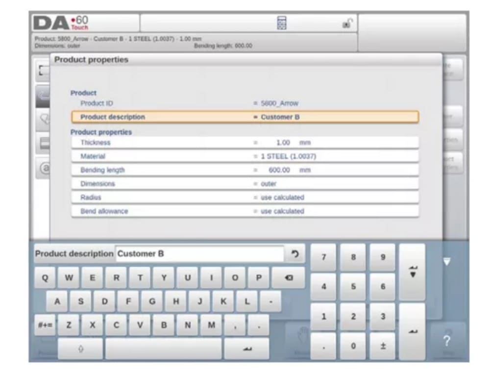
عند بدء رسم منتج جديد، تظهر شاشة تحتوي على خصائص المنتج العامة.
أولاً، ينبغي تحديد هذه الخصائص والبيانات العامة قبل البدء برسم المنتج.
(1) إضافة ملاحظات
عند الضغط على زر "تحرير الملاحظات"، تظهر نافذة جديدة يمكنك من خلالها تحرير النص المتعلق بالمنتج الحالي. تُعرض الأحرف الممكنة على لوحة المفاتيح.

2. رسم المنتج ثنائي الأبعاد
(1) المقدمة
بعد إدخال بيانات المنتج العامة تظهر شاشة الرسم.
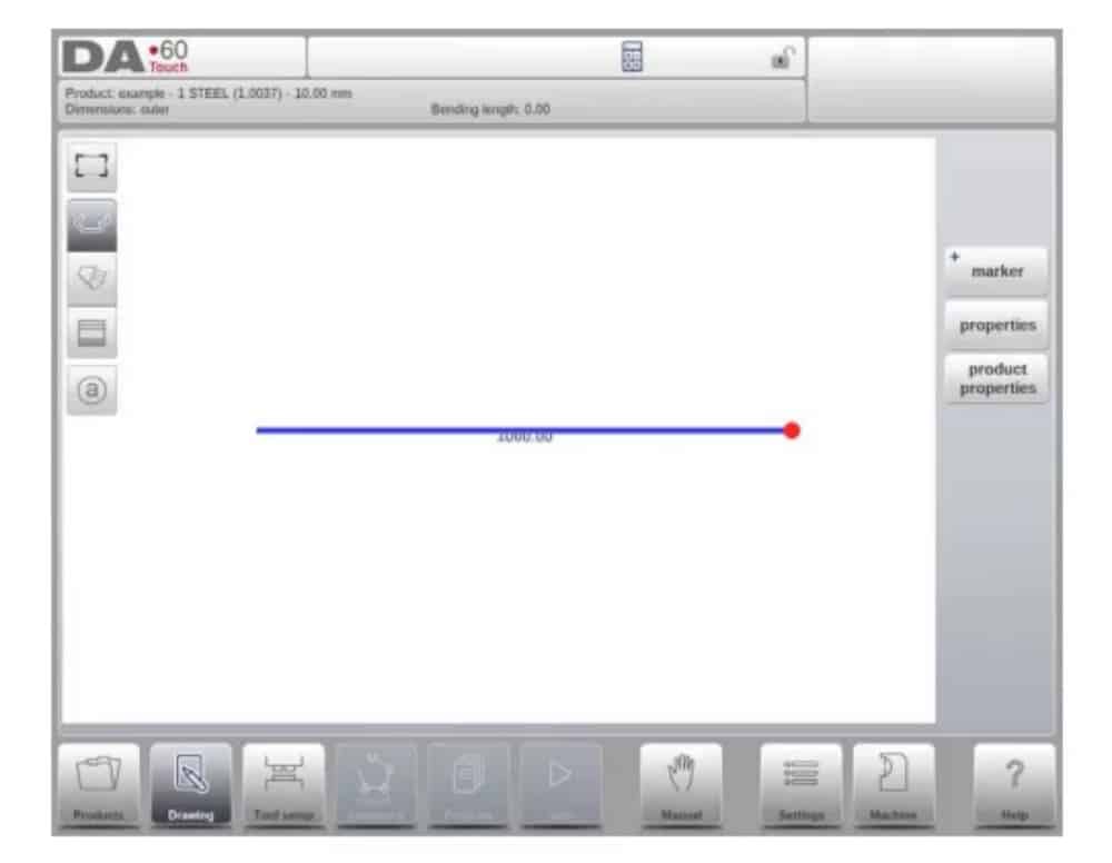
في صف المعلومات العلوي ستجد معلومات حول معرف المنتج ووصف المنتج واختيار الأبعاد الداخلية/الخارجية ودليل المنتج الفعلي.
الآن يمكنك إنشاء ملف تعريف المنتج. يمكنك ذلك باستخدام أصابعك للنقر وإنشاء المنتج بسرعة في وضع "الرسم". بعد ذلك، يمكنك إدخال أبعاد المنتج الحقيقية والقيم المقابلة باستخدام لوحة المفاتيح.
يمكنك أيضًا إدخال زاوية الانحناء وطول الضلع مباشرةً باستخدام لوحة المفاتيح وزر الإدخال. تظهر الخصائص في شريط الإدخال على لوحة المفاتيح. يستمر هذا الإجراء حتى يحصل المنتج على الملف الشخصي المطلوب.
يمكن تغيير بيانات المنتج باختيار "خصائص المنتج". كما يمكن تغيير خصائص زوايا المنتج وخطوطه باختيار "خصائص".
تكوين الأداة
1. المقدمة
2. الإجراء القياسي
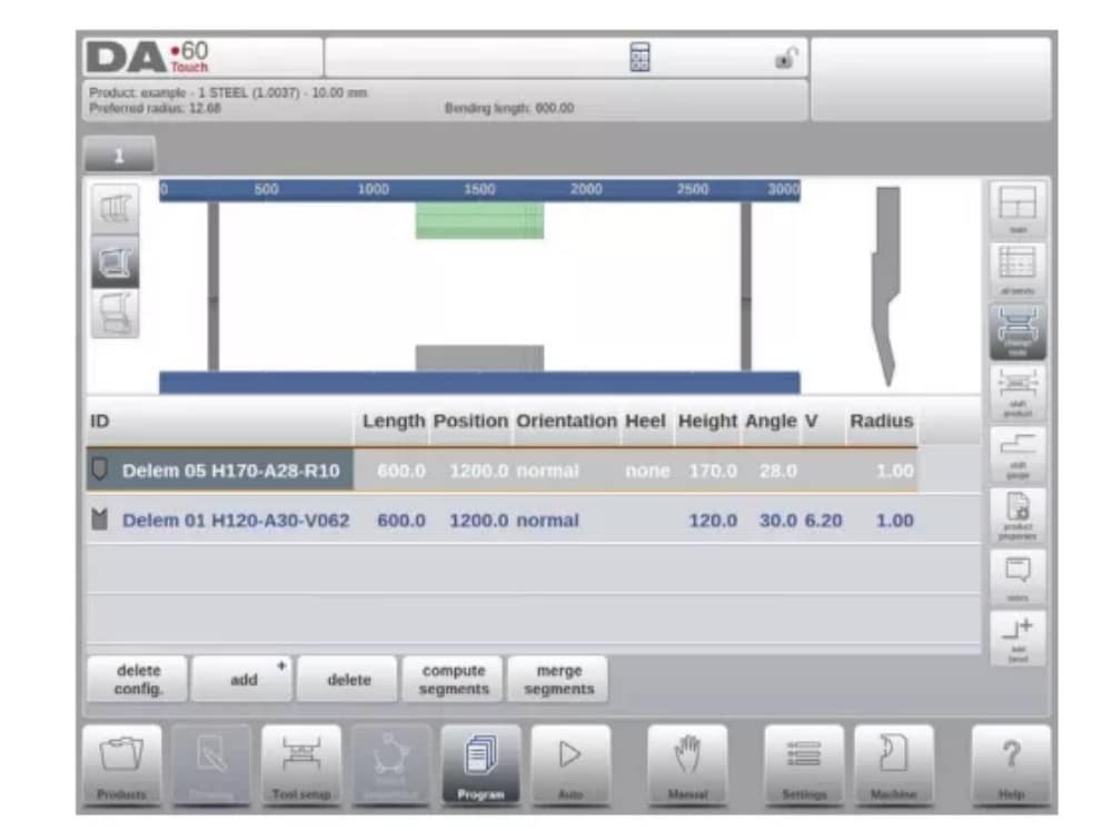
عند تفعيل وظيفة "إعداد الأدوات"، تُظهر الشاشة في النصف العلوي منها منظرًا أماميًا لإعدادات الماكينة. أما في النصف السفلي، فتُعرض بيانات الأدوات. في هذه الشاشة، يُمكن برمجة أماكن الأدوات في الماكينة.

3. اختيار الأدوات
عند بدء تكوين أداة جديدة، يكون فتح الماكينة فارغًا

حدد إضافة لإضافة أداة إلى التكوين؛ المثقبة أو القالب أو المحول (إذا تم تمكينه)

عندما يتم اختيار أداة (على سبيل المثال، لكمة)، يتم وضعها في الجهاز بأقصى طول متاح.

بعد وضع الأداة، يمكن تغيير معرف الأداة عن طريق تحديد معرف اللكمة في الشاشة والنقر على عرض القائمة.
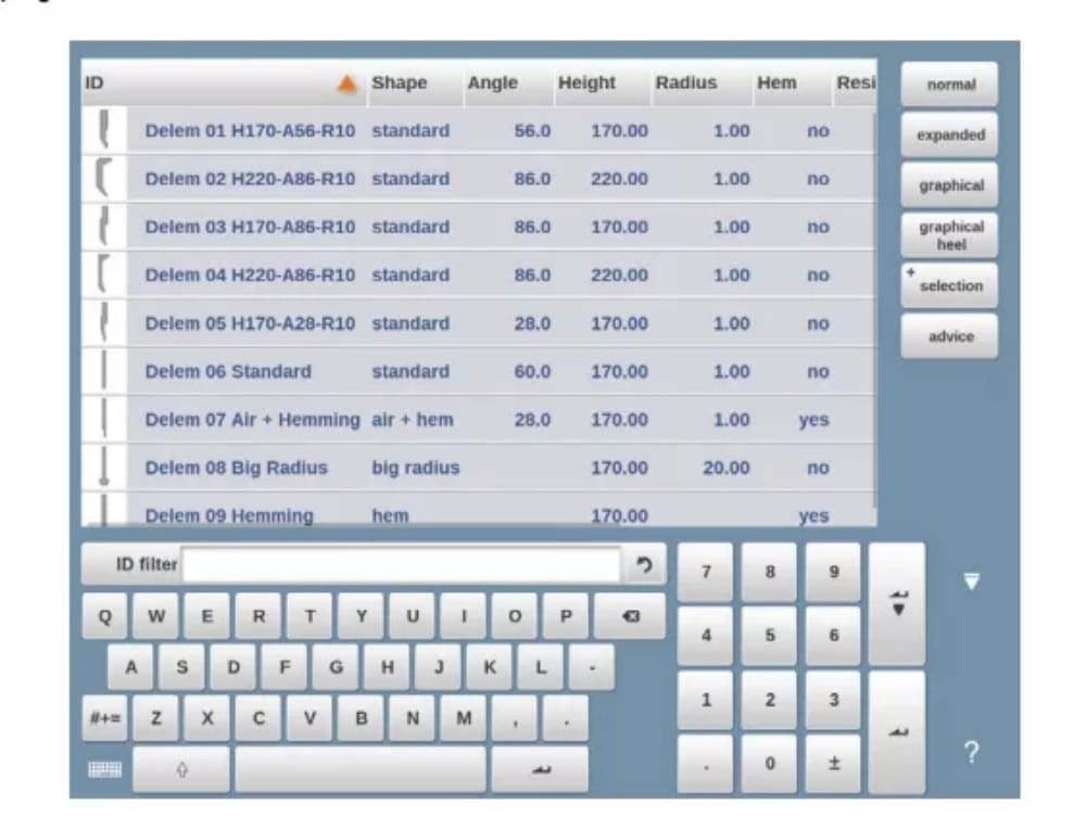
4. تقسيم الأدوات
عند استخدام أدوات مجزأة، والتي يمكن من خلالها تكوين أدوات بالحجم المطلوب، يمكن للتحكم أن يدعم هذا ويمكن أن يساعد في إنشاء التجزئة المناسبة.

في الفقرة التالية، يتم شرح وظيفة التجزئة، بما في ذلك استخدام ثلاثة عروض لإعداد الأداة. بجوار شاشة إعداد الأداة، تعتمد إمكانية توفر ميزات التجزئة على القطاعات المبرمجة لكل أداة. هذا
يمكن إجراء البرمجة في وضع الماكينة ضمن مكتبات Punches وBottom dies.
يمكنك العثور على مزيد من المعلومات حول برمجة المقاطع في مكتبة الأدوات في نهاية هذه الفقرة.
من شاشة إعداد الأداة، تتوفر ثلاثة أوضاع عرض. باستخدام أزرار الاختيار على يسار واجهة الجهاز، يمكنك اختيار الأوضاع التالية:
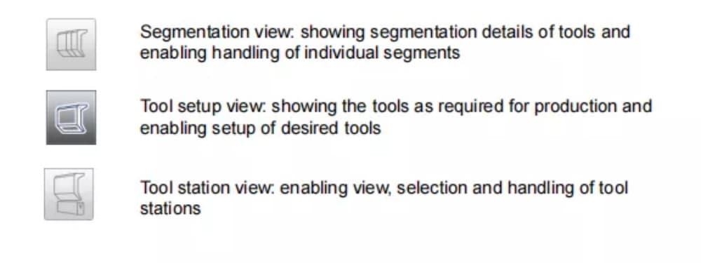
5. تقسيم الأدوات الفردية
بعد عملية إعداد الأدوات المطلوبة للمنتجات المراد تصنيعها، يتم ثني
يمكن لوضع التسلسل حساب تسلسل الانحناء الأكثر كفاءة.
يمكن تقسيم الأدوات حسب الرغبة، مما يساعد في اختيار الأجزاء وإنشاء طول الأداة الصحيح.
تحسب وظيفة تقسيم الأدوات تلقائيًا التقسيم المطلوب وتستخدم تعيينات "أقصى مسافة بين الأدوات" وعند الاختيار "تسامح طول الأداة" للعثور على أفضل حل

6. اختيار المحطة وإعادة تحديد موقعها
العرض الثالث لإعداد الأدوات هو عرض المحطة. في هذا العرض، تُبرز محطات الأدوات بالكامل عند تحديدها، ويمكن تغيير موضعها ببرمجة موضع بديل أو سحبها إلى الموضع الجديد المطلوب في الجهاز.
يتم تعريف محطة الأدوات تلقائيًا عند وجود تداخل بين المثقبات والقوالب. هذا يعني أن محطة الأدوات تُعتبر محطة عندما يكون موضع المثقب والقالب متقابلين تمامًا، على سبيل المثال. عندما يكون موضع المثقب والقالب متحركًا مع استمرار التداخل في
بين المثقب والقالب، يُعتبر هذا أيضًا محطة أدوات. حتى عندما يكون مثقبان متقابلان لقالب واحد، وهو ما قد يكون مفيدًا في حالات الانحناء المقيّد، يُعتبر هذا محطة أدوات. يمكن تغيير موضع هذه المحطات دون فقدان موقعها النسبي.

عرض المحطة لا يغير أي شيء في تفاصيل الأداة.
تسلسل الانحناء
1. المقدمة

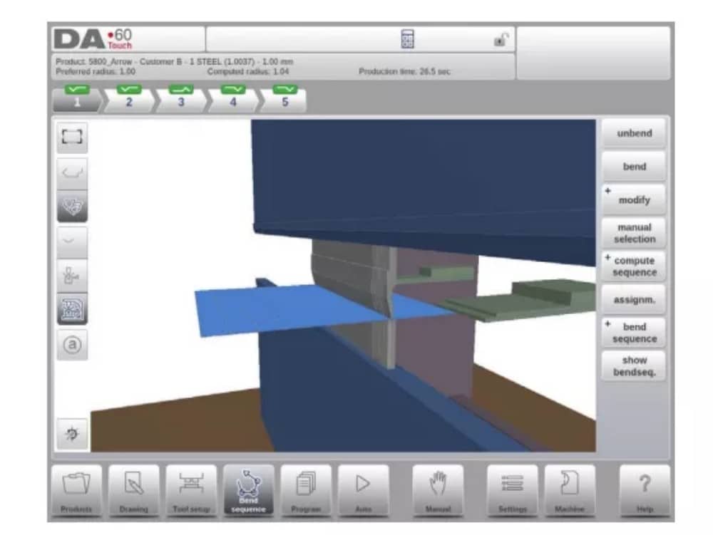
عند توفر تهيئة الأداة، يُمكن بدء محاكاة الانحناء لتحديد تسلسل انحناء للمنتج النشط. يبدأ تحديد تسلسل الانحناء بالنقر على زر التنقل "تسلسل الانحناء".

يمكن تحديد تسلسل الانحناء عن طريق الحساب التلقائي بدءًا من ناتج الانحناء. كما يمكن تحديد التسلسل يدويًا بدءًا من المسطح.
المنتج، لا يستخدم الحساب التلقائي.
في شاشة تسلسل الانحناء، يظهر المنتج بين الأدوات في آخر موضع انحناء محتمل. عند بدء المحاكاة، يظهر المنتج في حالته النهائية. للحصول على تسلسل انحناء، يجب فتح المنتج من آخر انحناء إلى أول انحناء. يمكن القيام بذلك باستخدام مفاتيح الوظائف المتاحة.
عندما يكون من المفضل البدء بمنتج غير مطوي لاختيار تسلسل الانحناء يدويًا، يمكن اختيار ذلك من خلال زر الأمر Bend Sequence.
(1) عرض التحديد
من الممكن تبديل طرق عرض الشاشة ضمن تسلسل الانحناء حسب الاختيار المطلوب.
تتواجد وظائف العرض مقابل أزرار الأوامر في الشاشة الرئيسية.
عرض الوظائف

(2) محدد الانحناء
ضمن شاشة تسلسل الانحناءات، يُمكن اختيار الانحناءات والتنقل خلالها باستخدام مُحدد الانحناءات. في أعلى الشاشة، يُشار إلى عدد الانحناءات باستخدام مُحددات الانحناءات الأولية. بعد إكمال تسلسل الانحناءات، تصبح جميعها ملونة وفعّالة، ويُظهر مؤشر انعطاف.

بعد ذلك، يُمكنك النقر على المنعطفات بسهولة لاختيار بيانات المنعطف المطلوبة. في مُحدِّد المنعطفات، سيُعرَض مؤشر الانعطاف بألوان الأخضر والأصفر والأحمر للإشارة إلى مدى الالتزام بتسلسل المنعطفات.

2. فك المنتج
لإنشاء برنامج CNC، يجب معرفة تسلسل الانحناء. هناك طريقتان لتحقيق ذلك:
• اضغط على مفتاح الوظيفة "حساب". سيقوم جهاز التحكم تلقائيًا بحساب أسرع عملية حسابية.
تسلسل الانحناء المحتمل لهذا المنتج.
• اضغط على مفتاح الوظيفة "فك الانحناء" بشكل متكرر، حتى يصبح المنتج غير منحني تمامًا.
عندما يصبح المنتج غير قابل للثني تمامًا، اضغط على وظيفة تسلسل الانحناء ثم على زر الحفظ لإنشاء برنامج CNC وحفظه.

3. الاختيار اليدوي للانحناءات
عادةً ما يقترح جهاز التحكم الانحناء التالي (أو غير التالي) في التسلسل. يتم حساب ذلك بواسطة جهاز التحكم بناءً على التخصيصات المبرمجة، وبالطبع شكل المنتج والأدوات المستخدمة. لأسباب مختلفة، قد يلزم اختيار انحناء آخر لتسلسل الانحناء. يمكن تغيير/تحديد تسلسل الانحناء من خلال وظيفة "يدوي".
الاختيار. عند اختيار وظيفة الاختيار اليدوي، تُفتح نافذة جديدة.

4. المهام
(1) المقدمة
التعيينات هي المعلمات التي يتم من خلالها التحكم في حساب تسلسل الانحناء.
يتم فتح شاشة التعيينات من شاشة تكوين الأداة باستخدام مفتاح الوظيفة
تعيين
تعمل حسابات تسلسل الانحناء التلقائي مع العديد من الشروط من أجل العثور على الحد الأدنى بين وقت الإنتاج الأدنى وإمكانيات المناولة دون تصادم المنتج/الآلة والمنتج/الأداة.
لإيجاد أحد الخيارات المثلى، يجب برمجة عدة معاملات حسابية لحساب تسلسل الانحناء. بعض هذه المعاملات متعلق بالآلة، وبعضها الآخر يتعلق بدقة المنتج، وإمكانيات المناولة، وأوقات الدوران.
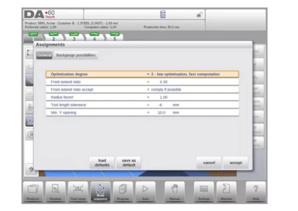
(2) المهام - العامة
درجة التحسين
المدى 1-5.
يجب إدخال عدد البدائل التي سيتم حسابها لكل منحنى هنا.
كلما ارتفع هذا الرقم، زاد عدد البدائل التي يتعين على عنصر التحكم فحصها، وبالتالي سيستغرق وقت الحوسبة وقتًا أطول:
1- أقل قدر من التحسين، وأسرع عملية حسابية
2- تحسين منخفض، حساب سريع
3- تحسين المتوسط، الحوسبة المتوسطة
4- تحسين عالي، حساب بطيء
5 - أعلى تحسين، أبطأ حساب
(3) المهام - إمكانيات القياس الخلفي

5. إظهار تسلسل الانحناء
عند الضغط على وظيفة إظهار تسلسل الانحناء، يتم عرض نظرة عامة رسومية لتسلسل الانحناء.

يمكن تفعيل هذا الخيار في أي وقت بعد إجراء أول عملية فك انحناء. تعرض النظرة العامة الرسومية الانحناءات المحددة، بالإضافة إلى الانحناءات غير المحددة (علامة الاستفهام).
يمكن تكبير أو تصغير كل صورة في العرض العام بشكل منفصل باستخدام الوظائف المتاحة. كما يمكن تدوير الصور بحركة الأصابع.
برمجة المنتج
1. المقدمة

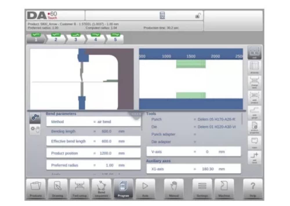
لتحرير برنامج CNC موجود، حدد منتجًا من قائمة المنتجات، ثم انقر على زر التنقل "برنامج". عند بدء برنامج جديد، انقر على "برنامج جديد"، وبعد إدخال خصائص المنتج الرئيسية وإعدادات الأدوات، سينتقل النظام تلقائيًا إلى "برنامج".
في كلتا الحالتين، ستظهر الشاشة الموضحة أعلاه. تتم برمجة البيانات وتغييرها بنفس الطريقة في كلتا الحالتين.
تعرض الشاشة الرئيسية البرنامج الرقمي الحالي، أو عند بدء برنامج جديد، أول منحنى مُبرمج. يُمكن استخدام مُحدد المنحنيات في أعلى الشاشة للتنقل بين المنحنيات. يُمكن النقر على المنحنيات المُشار إليها لاختيار بيانات المنحني المطلوبة بسهولة.
على جانب الشاشة الرئيسية، يتم الإشارة إلى العروض والوظائف باستخدام أزرار الأوامر.
الوظائف
الأوضاع/الوظائف التالية متاحة:

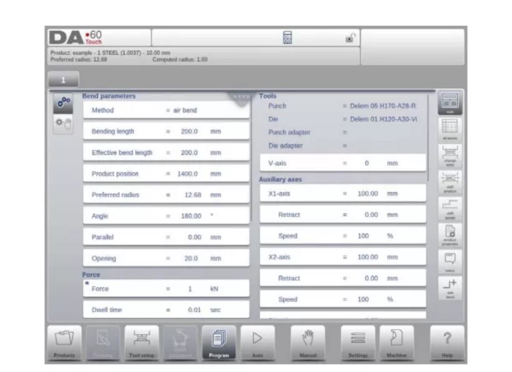
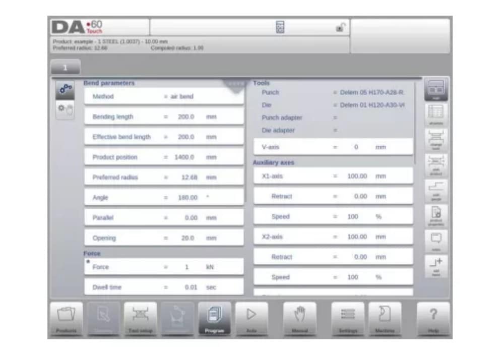
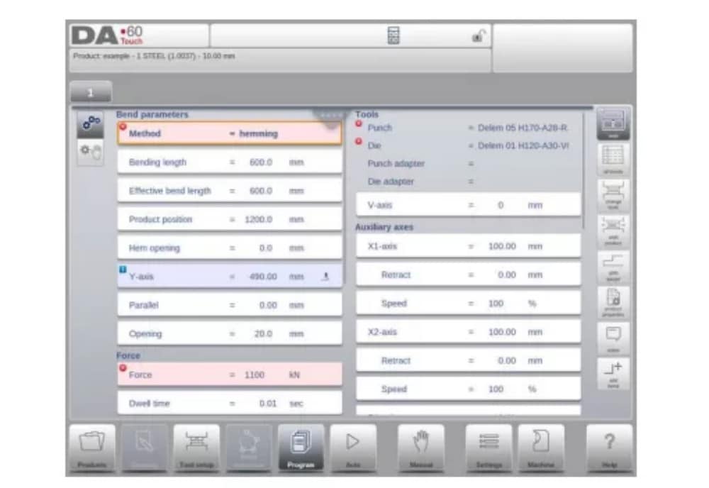
2. وضع البرنامج، شرح المعلمات
تعرض الشاشة الرئيسية الانحناءات المتاحة، ومن هذه الشاشة الرئيسية، من كل انحناء متاح، يمكن عرض معلمات محددة وتحريرها.
يتم عرض معرف المنتج ووصف المنتج في الصف العلوي على الشاشة.
في حالة المنتج الرسومي، يمكن أيضًا عرض المعلومات الرسومية.
(1) معلمات الانحناء
طرق الانحناء

(2) القوة
قوة
الحد الأقصى للقوة المعدلة أثناء الضغط (يتم حسابها تلقائيًا).
وقت البقاء
زمن تثبيت اللكمة عند نقطة الانحناء.
سرعة
سرعة
سرعة العمل (سرعة الضغط). في البداية، يتم نسخ قيمة هذه المعلمة من معلمة سرعة الضغط الافتراضية في وضع الإعدادات.
الوظائف
تكرار
0 = تم تخطي الانحناء
من 1 إلى 99 = عدد المرات التي سيتم فيها تكرار هذا الانحناء.
3. أوضاع التحرير / العرض
(1) جميع الانحناءات
عند الضغط على وظيفة All Bends، تظهر نظرة عامة كاملة على الانحناءات.

من هذه الشاشة، يُمكنك تحرير برنامج CNC كاملاً. يُمكنك تحرير جميع معلمات الانحناء داخل الجدول، كما يُمكنك تبديل الانحناءات ونقلها وإضافتها وحذفها.
يمكن التمرير عبر الأعمدة المتاحة عن طريق حركة الإصبع/السحب.
(2) تغيير الأدوات
لتغيير الأدوات، يُمكن استخدام قائمة "إعداد الأداة". عند استخدام وضع البرمجة الرقمية، يُستخدم "إعداد الأداة" بشكل قياسي. إذا لزم تغيير إعداد الأداة لخطوة انحناء واحدة فقط، يُمكن استخدام زر "تغيير الأدوات". سيسألك عنصر التحكم دائمًا عما إذا كان يجب إجراء التغييرات على الإعداد بأكمله أم لثنية واحدة فقط. إذا لزم الأمر، فسيتم التبديل تلقائيًا إلى قائمة "إعداد الأداة".
4. معلمات البرمجة
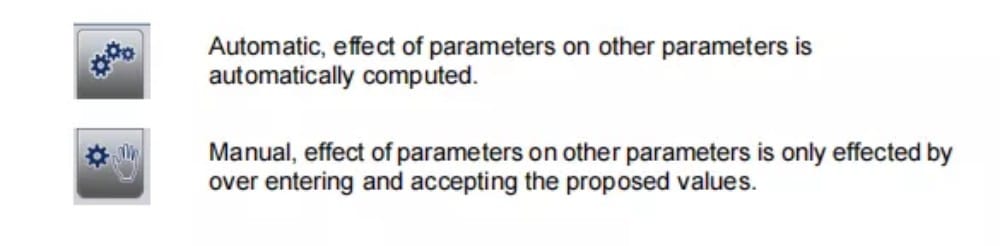
يمكن برمجة المعلمات في وضع البرمجة واحدًا تلو الآخر. ويمكن حساب تأثير المعلمة على المعلمات الأخرى تلقائيًا أو يدويًا. ويعتمد ذلك على الوضع المحدد على يسار الشاشة. يتيح لك مفتاح الحساب التلقائي الاختيار بين:
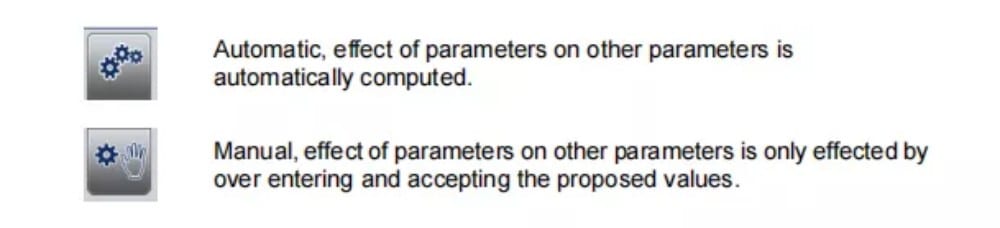
يتم تصور العلاقة بين المعلمات باستخدام رمز ولون الخلفية.
الوضع التلقائي
1. مقدمة
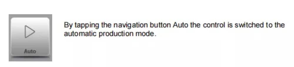
في الوضع التلقائي مع تفعيل البرنامج، يمكن بدء الإنتاج. بعد تفعيل الوضع التلقائي، اضغط على زر البدء لبدء الإنتاج.
يُنفِّذ الوضع التلقائي البرنامج تلقائيًا بعد الضغط على زر البدء. عند اختيار منتج آخر في وضع المنتجات، وهو موجود في المكتبة ومُستخدَم للإنتاج، يُمكن التبديل فورًا إلى الوضع التلقائي وبدء الإنتاج.
في كل مرة تختار فيها برنامج ثني مختلفًا، يجب عليك التحقق من أدواتك ومواضعها في جهازك. يُشار إلى ذلك أيضًا برسالة تحذيرية "تحقق من الأدوات" عند دخولك الوضع التلقائي.
2. أوضاع العرض
توفر شاشة الوضع التلقائي مجموعة متنوعة من طرق العرض، والتي يمكن اختيارها حسب طريقة الإنتاج. عند اختيار الوضع التلقائي لأول مرة، ستظهر الشاشة الرئيسية. على يمين الشاشة، يمكنك اختيار طرق العرض المتاحة.
أوضاع العرض التالية متاحة:
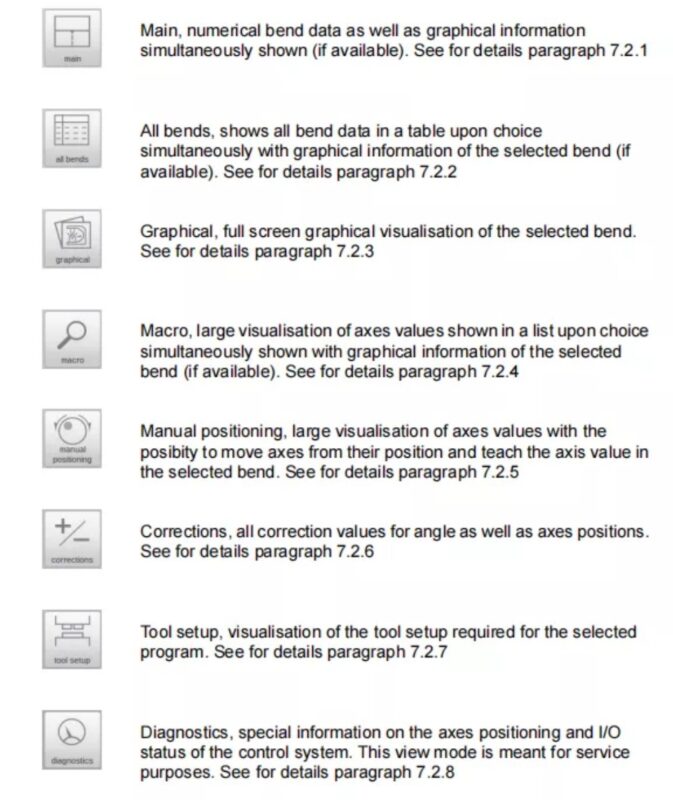
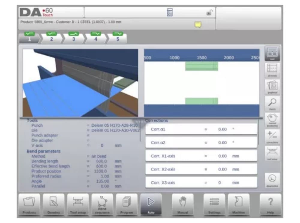
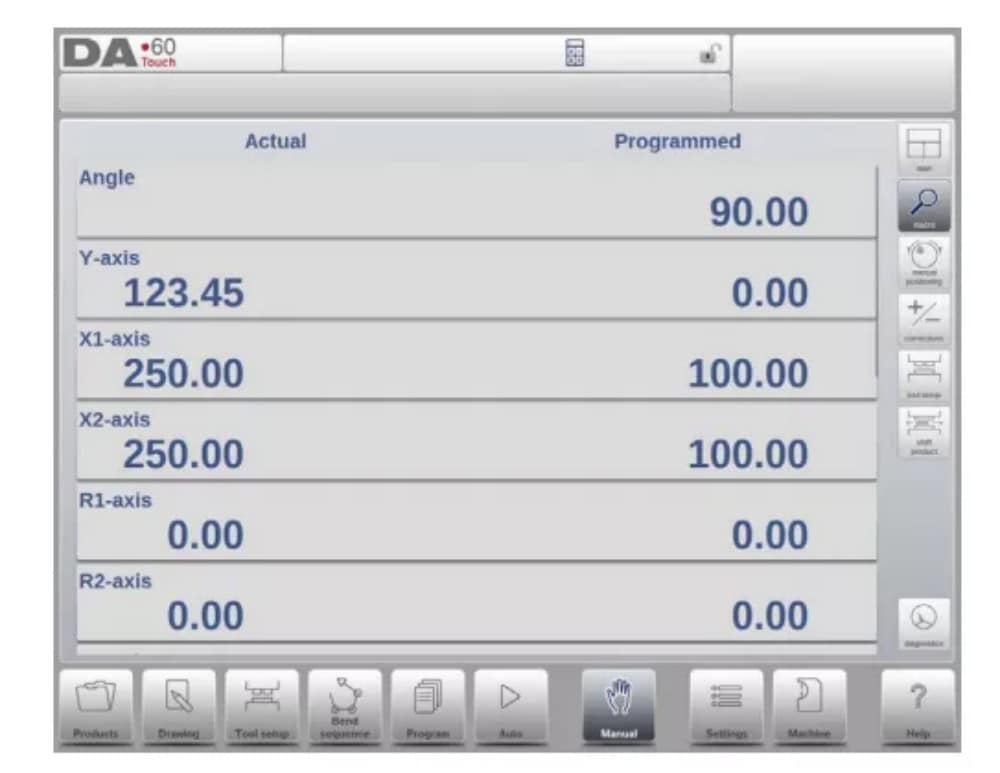
(1) الرئيسي
يُظهر العرض الرئيسي البيانات الرقمية للانحناء مع التصحيحات. يمكن برمجة التصحيحات هنا. يفصل عنصر التحكم المُقسّم الشاشة في عرض رسومي والبيانات الرقمية. يمكن إغلاقه إذا كانت البيانات الرقمية فقط مطلوبة.
(2) جميع الانحناءات
يُظهر وضع عرض جميع الانحناءات، سواءً بفتح لوحة الرسوم البيانية أم لا، جدولاً يتضمن جميع بيانات الانحناءات. تُعرض الانحناءات صفاً، بينما تُعرض جميع معلمات الانحناء في الأعمدة.

(3) رسومية
في وضع العرض الرسومي، يتم تقديم عرض رسومي كامل الشاشة لعملية الانحناء.

(4) الماكرو
في وضع عرض الماكرو، ينتقل عنصر التحكم إلى عرض يعرض قيم المحاور الكبيرة فقط على الشاشة. يمكن استخدام هذا العرض عند العمل بعيدًا قليلاً عن عنصر التحكم، مع إمكانية قراءة قيم المحاور.

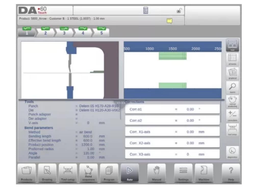
(5) التموضع اليدوي
في وضع عرض تحديد المواقع اليدوي، تُعرض قيم المحاور بشكل كبير. يمكن تحديد المحاور، وعند تحديدها، يمكن التحكم في موضعها بتدوير عجلة اليد.
مؤشر التدريس:

عند الضغط على سهم مؤشر التعليم، والوقوف بين القيمة الفعلية والقيمة المبرمجة، يتم نقل القيمة إلى خطوة البرنامج
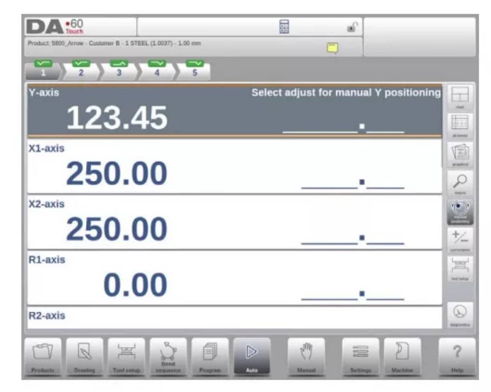
3. ملاحظات
يمكن عرض الملاحظات التي يمكن إضافتها إلى منتج أو برنامج في الوضع التلقائي.
مع وجود مؤشر الملاحظات، فهذا يشير إلى أنه تمت إضافة ملاحظات إلى هذا المنتج، وعند النقر على المؤشر سيتم عرضها.
يمكن إضافة ملاحظات عامة إلى منتج أو برنامج، وكذلك إلى ملفات محددة. يمكن أيضًا تضمين مستندات PDF داخل الملاحظات. سيؤدي الضغط على زر PDF إلى فتح المستند.
4. تصحيح الاصطدام
في حالة وجود انحناءة ارتطام محددة، يُمكن إدخال تصحيح عام لها. هذه الوظيفة متاحة فقط إذا كان المنتج مُحمّلاً بانحناءة ارتطام.
عند استخدام Bumping Corr. تظهر نافذة جديدة يمكنك من خلالها إدخال التصحيح.

الوضع اليدوي
1. المقدمة
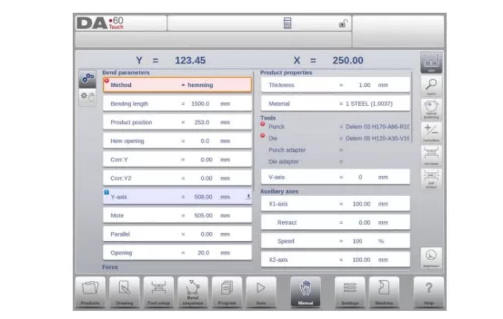
في الوضع اليدوي، يمكنك برمجة معلمات انحناء واحد. هذا الوضع مفيد للاختبار والمعايرة والانحناءات الفردية.
الوضع اليدوي مستقل عن الوضع التلقائي ويمكن برمجته بشكل مستقل عن البرامج الموجودة في الذاكرة.
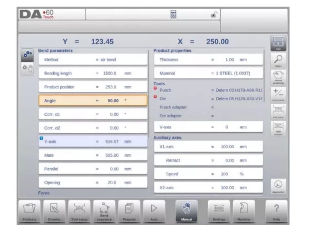
2. معلمات البرمجة والعروض
يمكن برمجة المعلمات في الوضع اليدوي واحدة تلو الأخرى. ويمكن حساب تأثير المعلمة على المعلمات الأخرى إما تلقائيًا أو يدويًا. ويعتمد ذلك على الوضع المحدد على الجانب الأيسر من الشاشة. يتيح مفتاح الحساب التلقائي
اختر بين:
يتم تصور العلاقة بين المعلمات باستخدام رمز ولون الخلفية.
3.ماكرو
باستخدام الماكرو، ينتقل عنصر التحكم إلى عرض جديد يعرض قيم المحاور الكبيرة فقط على الشاشة. يمكن استخدام هذا العرض عند العمل بعيدًا قليلاً عن عنصر التحكم، مع إمكانية قراءة قيم المحاور.
4. الحركة اليدوية للمحاور
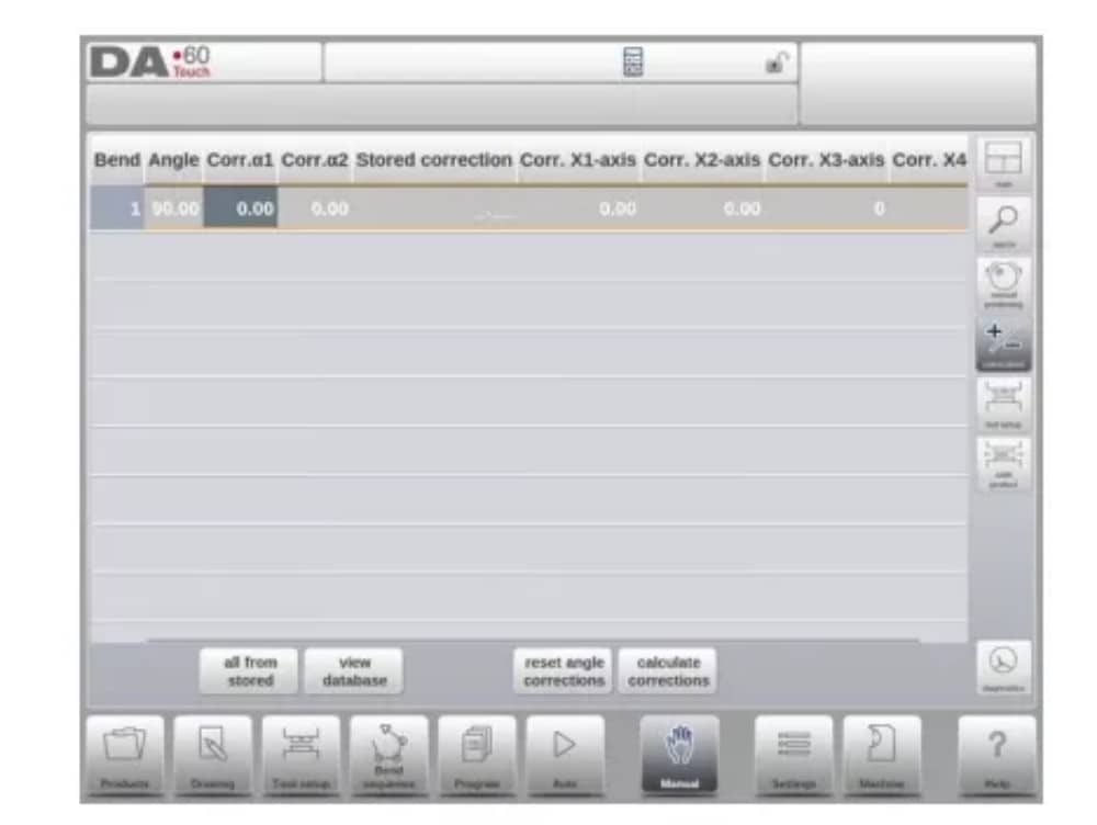
5. التصحيحات
في وضع العرض هذا، تُعرض تصحيحات الانحناء المُبرمجة في الوضع اليدوي. ولأن هذا الانحناء دائمًا ما يكون انحناءً واحدًا، فسيتم عرض خط واحد.
6. التشخيص
عند النقر على "التشخيصات"، ينتقل عنصر التحكم إلى عرض يعرض حالة المحاور. في هذه النافذة، يُمكنك مُتابعة الحالة الحالية للمحاور المُتاحة. كما يُمكن تفعيل هذه الشاشة أثناء تشغيل عنصر التحكم، ما يُتيح مُراقبة سلوكه أثناء دورة الانحناء.

إعدادات
1. المقدمة

يتيح وضع الإعدادات للتحكم، والذي يمكن العثور عليه في لوحة التنقل، الوصول إلى جميع أنواع الإعدادات التي تؤثر على برمجة المنتجات والبرامج الجديدة.
يمكن تعيين القيم الافتراضية والقيود المحددة.
تُقسّم الإعدادات إلى عدة علامات تبويب تُنظّم المواضيع المختلفة منطقيًا. في الأقسام التالية، تُناقش علامات التبويب المتاحة والإعدادات المُفصّلة.

2. عام
حدد علامة التبويب المطلوبة وانقر على المعلمة المراد تغييرها. عندما تكون المعلمات ذات قيمة رقمية أو أبجدية، ستظهر لوحة المفاتيح لإدخال القيمة المطلوبة. عند اختيار الإعداد أو المعلمة من قائمة، ستظهر القائمة ويمكن تحديدها.
يتم ذلك بالضغط. القوائم الأطول تسمح بالتمرير عموديًا للتحقق من العناصر المتاحة.
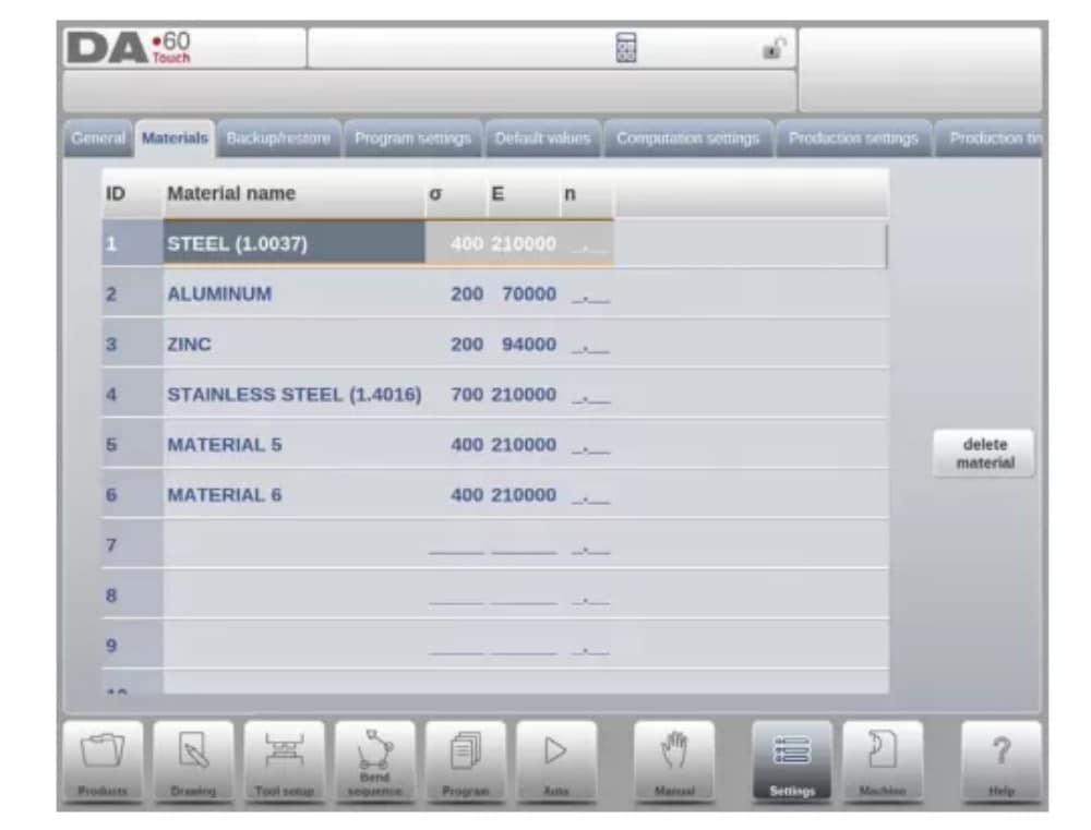
3. المواد
في هذه التبويبة، يُمكن برمجة المواد وخصائصها. يُمكن تعديل المواد الموجودة، وإضافة مواد جديدة، أو حذف مواد موجودة. يُمكن برمجة 99 مادة كحد أقصى على وحدة التحكم.
4. النسخ الاحتياطي / الاستعادة
تتيح هذه علامة التبويب إمكانية النسخ الاحتياطي واستعادة المنتجات والأدوات، بالإضافة إلى الإعدادات والجداول. عند استخدام منتجات أو أدوات من نماذج تحكم قديمة، يمكن أيضًا استعادة المنتجات والأدوات بتنسيق ملفات DLC باستخدام وظيفة الاستعادة هذه.
بالنسبة للمواد، تتوفر نسخة احتياطية محددة واستعادة لها هنا.
يمكن نسخ الأدوات والمنتجات احتياطيًا واستعادتها وفقًا للإجراءات التالية. تتشابه إجراءات حفظ البيانات أو قراءتها لجميع أنواع وسائط النسخ الاحتياطي: مثل الشبكة أو ذاكرة USB.

يتكون دليل النسخ الاحتياطي الفعلي من جهاز (ذاكرة تخزين USB، شبكة) ودليل. يعتمد اختيار الأجهزة على الأجهزة المتصلة بوحدة التحكم. عند الحاجة، يمكن إنشاء أدلة وتحديدها. يمكن تحديد مواقع النسخ الاحتياطي لتخزين المنتجات والأدوات بشكل مستقل.
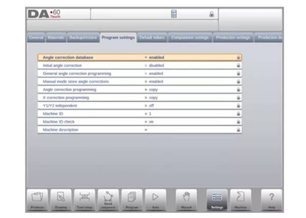
5. إعدادات البرنامج
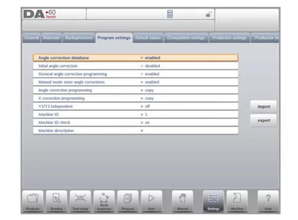
قاعدة بيانات تصحيح الزاوية
معلمة لتمكين قاعدة البيانات باستخدام تصحيحات الزاوية.
6. القيم الافتراضية
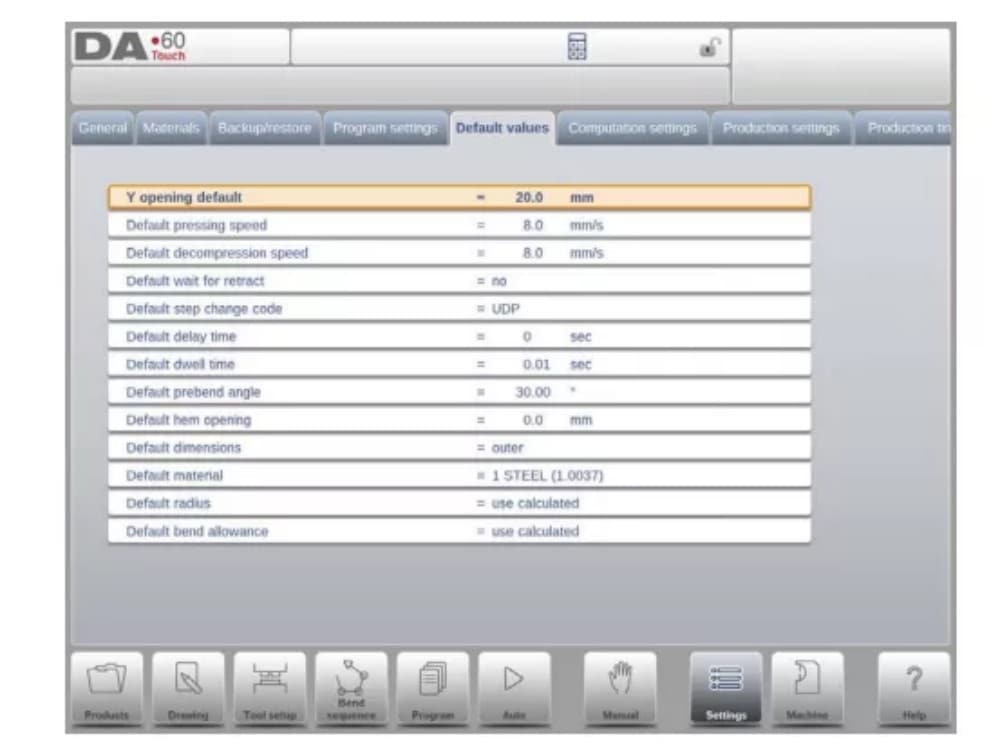
Y الافتتاح الافتراضي
فتح المحور Y الافتراضي، يستخدم كقيمة أولية للمعلمة 'فتح' في برنامج جديد.
7. إعدادات الحساب
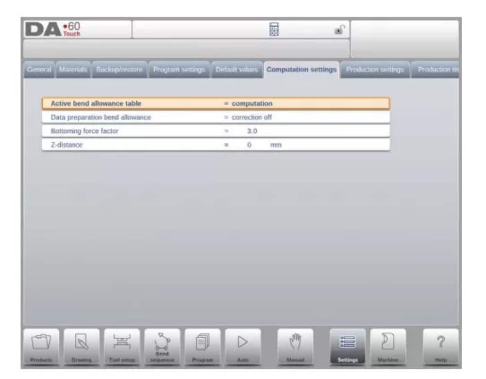
جدول بدل الانحناء النشط
الحساب => سيحسب عنصر التحكم جدول بدل الانحناء => سيتم استخدام جدول بدل الانحناء
بدل الانحناء هو تصحيح المحور X بسبب تقصير الورقة بعد الانحناء.
باستخدام هذه المعلمة، يتم اختيار طريقة حساب بدل الانحناء. "الحساب" يعني استخدام الصيغة القياسية للتحكم لحساب بدل الانحناء.
تعني عبارة "الجدول" جدول بدل الانحناء مع إمكانية استخدام قيم التصحيح.
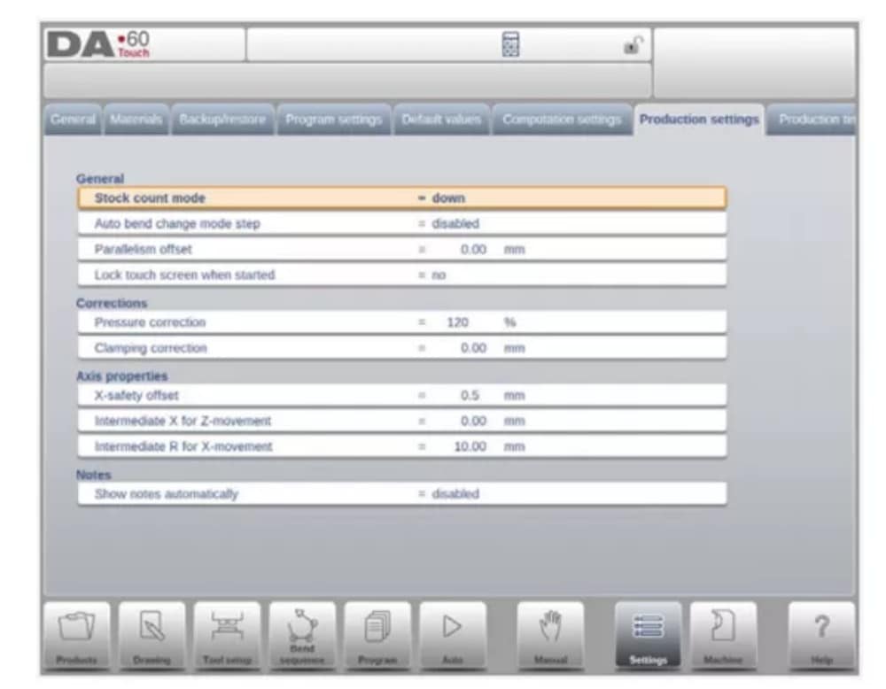
8. إعدادات الإنتاج
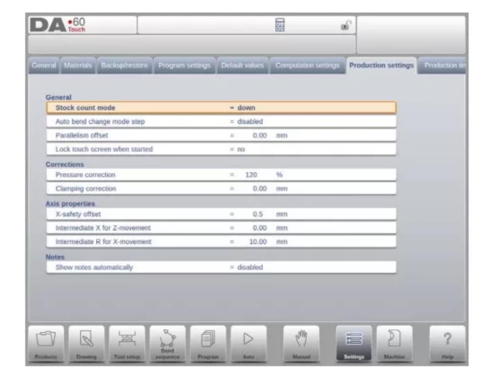
وضع عد المخزون
إعداد عداد المخزون في وضع الإنتاج، لجعل عداد المخزون (عداد المنتج) يحسب تصاعديًا أو تنازليًا.
عند اختيار العد التنازلي، ينخفض عداد المخزون في وضع الإنتاج بعد كل دورة إنتاج. عند وصول العداد إلى الصفر، يتوقف التحكم.
في الإجراء التالي، يتم إعادة تعيين قيمة عد الأسهم إلى قيمتها الأصلية.
عند تحديد العد التصاعدي، يتم زيادة العداد بعد كل دورة منتج.
يمكن أن يكون العد التنازلي مفيدًا عند الحاجة إلى إنتاج حصة مُخطط لها مسبقًا. ويمكن استخدام العد التصاعدي لإعداد تقرير عن تقدم الإنتاج.
9. حساب وقت الإنتاج
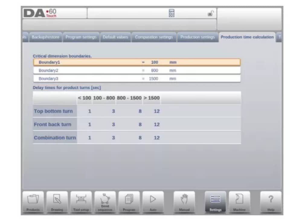
تُستخدم المعلمات في هذه الصفحة لحساب وقت إنتاج المنتج في عملية حساب تسلسل الانحناء. يعتمد هذا الوقت على سرعة وضع المحاور وأوقات مناولة المنتج. وتعتمد سرعة وضع المحاور على إعدادات الآلة.
10. إعدادات الوقت

وقت العرض
عرض التاريخ والوقت على لوحة العنوان، أو الوقت فقط أو لا يوجد وقت على الإطلاق.
آلة
1. المقدمة
يتيح وضع الماكينة للتحكم، والذي يمكن العثور عليه في لوحة التنقل، الوصول إلى عناصر تكوين الماكينة وخصائص الماكينة المحددة التي تؤثر على الحسابات العامة وسلوك الماكينة.
تُقسّم الإعدادات إلى عدة علامات تبويب تُنظّم المواضيع المختلفة منطقيًا. في الأقسام التالية، تُناقش علامات التبويب المتاحة والإعدادات المُفصّلة.
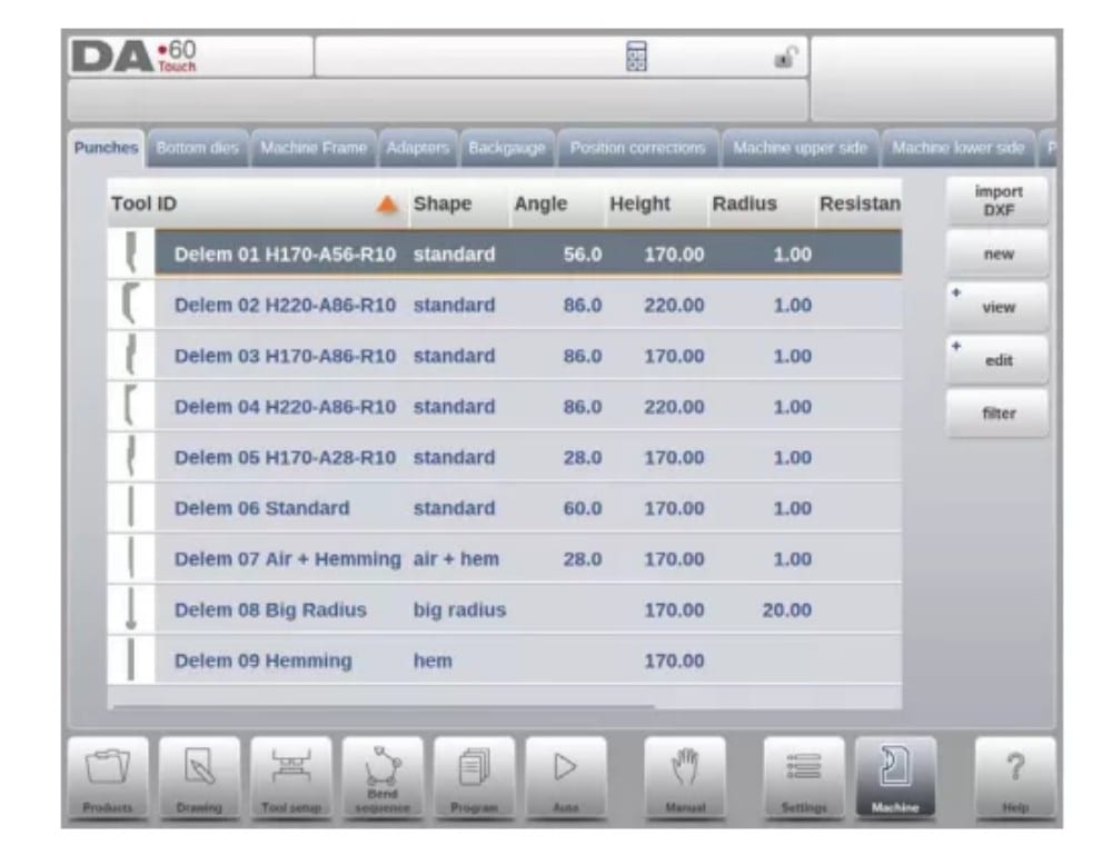
2. برمجة اللكمات
في هذه التبويبة، يُمكن برمجة اللكمات المستخدمة في الآلة. يُمكن إضافة لقم جديدة، وتعديل اللكمات الموجودة، ونسخها، وإعادة تسميتها، وحذفها.
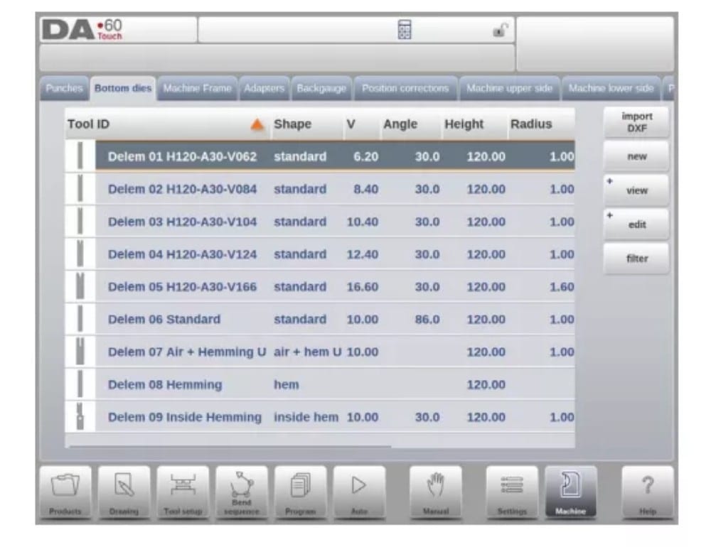
3. برمجة القوالب السفلية
في هذه التبويبة، يُمكن برمجة القوالب السفلية المُستخدمة في الآلة. يُمكن إضافة قوالب جديدة، وتعديل القوالب الموجودة، ونسخها، وإعادة تسميتها، وحذفها.
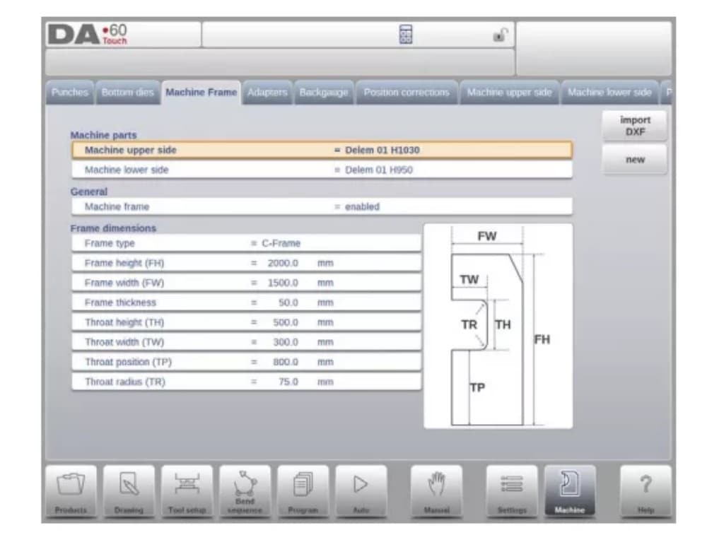
4. إطار الآلة
في هذه التبويبة، يُمكن تحديد وضبط هندسة الآلة النشطة من العارضة العلوية والسفلية والإطارات الجانبية. كما يُمكن برمجة تعريف الآلة هنا.
بجانب الجانب العلوي والجانب السفلي للماكينة، والتي يتم اختيارها من بين المتاحة، يمكن برمجة أبعاد إطار الجانب في هذه الصفحة.
يتم عرض شكل الماكينة على شاشة المحاكاة أثناء البرمجة الرسومية ويتم استخدامها لاكتشاف الاصطدام بين قطعة العمل والماكينة.
5. المحولات
في هذه الصفحة، يمكن تمكين محولات الأدوات وبرمجتها.
عند اختيارك، يمكنك تفعيل المحولات العلوية والسفلية. كما يمكنك ضبط المحول الافتراضي، الذي سيتم اختياره عند إضافة محول إلى إعدادات الأداة.
عند إضافة مُحوِّل، يجب تحديد المعلمات الأساسية بناءً على قالب. في المرحلة الثانية، يُمكن رسم تفاصيل المُحوِّل كأي مُثقاب أو قالب آخر.
6. مقياس الخلفية
عند حساب أبعاد مؤشر المقياس الخلفي، تُؤخذ حركة المحور R وحركة المحور X المرتبطة بها في الاعتبار. كما يُحسب تصادم قطعة العمل مع مؤشر المقياس الخلفي باستخدام هذه الأبعاد.
7. تصحيحات الموضع

8. الجانب العلوي للماكينة
في هذه التبويبة، يُمكن برمجة هندسة الآلة للشعاع العلوي، كملف تعريفي. تُستخدم هذه المعلومات في كشف التصادمات بين المنتج والآلة.
عند إضافة أدوات مساعدة مثل eg إلى الجهاز في حالات خاصة، يمكن برمجتها كشكل خاص للجهاز لتمكين حسابات الاصطدام من أخذ ذلك في الاعتبار.
في أغلب الحالات، يوجد شكل واحد فقط مبرمج.
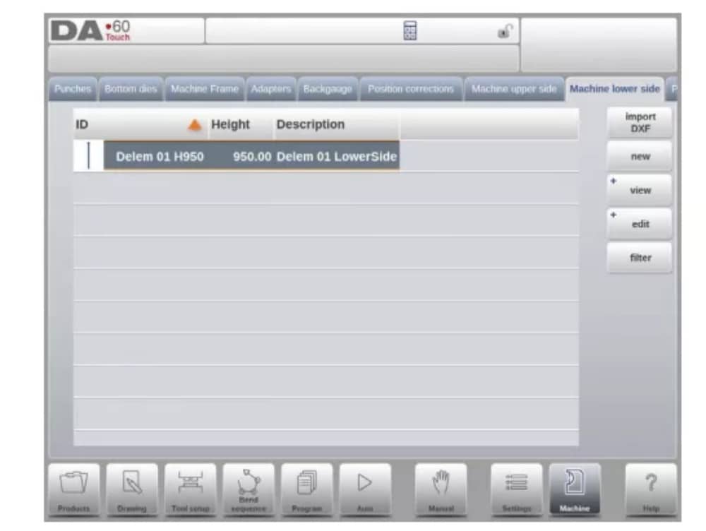
9. الجانب السفلي للماكينة
في هذه علامة التبويب، يمكن برمجة هندسة الماكينة للجانب السفلي (الجدول)، كملف تعريفي.
يتم استخدام هذه المعلومات في اكتشاف الاصطدامات بين المنتج والآلة.
عند إضافة أدوات مساعدة مثل eg إلى الجهاز في حالات خاصة، يمكن برمجتها كشكل خاص للجهاز لتمكين حسابات الاصطدام من أخذ ذلك في الاعتبار.
في أغلب الحالات، يوجد شكل واحد فقط مبرمج.
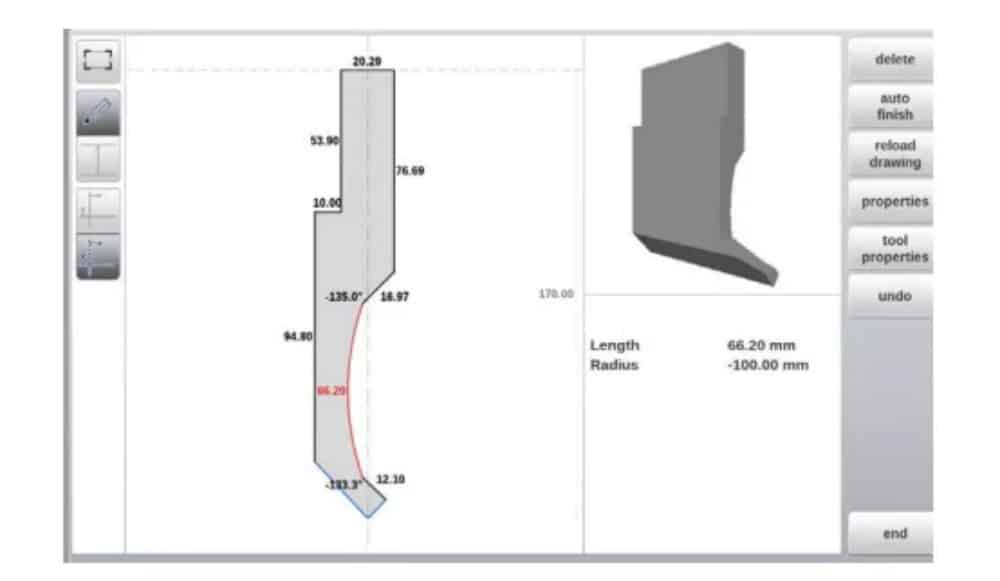
10. وظيفة الرسم للأدوات والمحولات وأشكال الآلات
في برمجة اللكمات والقوالب والمحولات وأشكال الآلات، بعد البيانات الرئيسية، يوفر التحكم إمكانية رسم الشكل المطلوب بحرية في الكائن.
تجعل الوظيفة الكائنات تبدو أكثر واقعية، ولكن الأهم من ذلك كله هو تمكين التحكم من القيام بمنع الاصطدام بدقة.
11. استيراد DXF للأدوات والمحولات وأجزاء الآلات
داخل مكتبة الأدوات، اللكمات، القوالب السفلية، المحولات بالإضافة إلى أشكال الآلة، الجانب العلوي للآلة، الجانب السفلي للآلة وإطار الآلة، يمكن للمرء العثور على DXF الاختياري
دالة الاستيراد. تتيح هذه الدالة استيراد المخطط من ملف DXF.
يؤدي استيراد DXF إلى فتح متصفح الملفات مما يتيح اختيار ملف DXF بالشكل المطلوب.

12. المنقلة

13. تسجيل الأحداث
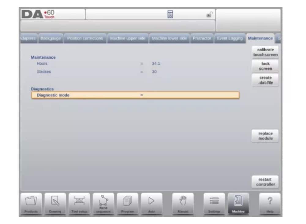
14. الصيانة
في هذه التبويبة، ستجد وظائف الصيانة. بجانب عداد ساعات تشغيل الآلة وعداد أشواطها، يمكنك أيضًا العثور على وظائف للمساعدة في استبدال الوحدات وتخزين بيانات التشخيص.
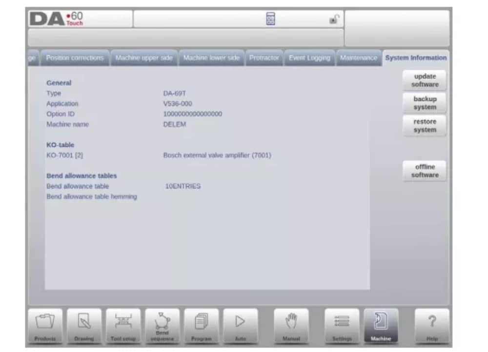
15. معلومات النظام
في هذه التبويبة، يمكنك العثور على معلومات النظام. إلى جانب معلومات إصدار البرنامج، يمكنك أيضًا قراءة معرفات الوحدات المُثبّتة وإصدارات الملفات الخاصة بشركة OEM.
بالإضافة إلى المعلومات، تتوفر هنا أيضًا وظيفة تحديث البرامج.
بروفايل-تي
1. المقدمة
(1) عام
يوفر برنامج Profile-T غير المتصل بالإنترنت واجهة مستخدم مشابهة لواجهة تحكم DA-Touch Line Delem. يُنصح باستخدام الفصول السابقة، التي تصف تشغيل واستخدام تحكم DA-Touch، كمرجع لاستخدام هذا البرنامج غير المتصل بالإنترنت. سيركز هذا الفصل على بعض الوظائف الخاصة المتوفرة فقط في برنامج Profile-T.
(2) متطلبات النظام
لتشغيل Profile-T على جهاز كمبيوتر، يجب أن يكون مجهزًا على الأقل بالميزات التالية:
• جهاز كمبيوتر متوافق مع IBM؛
• الحد الأدنى لدقة الشاشة هو 1024×768
• ويندوز XP / ويندوز 7؛
• مشغل الأقراص المضغوطة (CD-ROM) (فقط لأنظمة الأقراص المضغوطة الموزعة)؛
• منفذ USB مجاني
(3) توزيعات ودلائل Profile-T
اعتمادًا على حزمة الشراء، يتم توزيع برنامج Profile-T على قرص مضغوط أو يمكن إنشاؤه في وحدة التحكم.
2. عملية Profile-T
(1) مبدأ بروفايل-تي
الشكل التالي يوضح صفحة البداية لـ Profile-T:
(2) مكتبة الآلة
من المهم أن تكون المعلمات الموجودة في Profile-T هي نفسها الموجودة في عنصر التحكم الموجود على الجهاز.
بهذه الطريقة، تكون البرامج المُولَّدة دون اتصال بالإنترنت متوافقة مع نظام التحكم ١٠٠١TP3T. في Profile-T، يمكنك تثبيت عدة آلات لاستخدام محطة برمجة واحدة دون اتصال بالإنترنت لمجموعة الآلات الكاملة في قاعة الإنتاج.
(3) وظيفة الطباعة (Profile-T2D وProfile-T3D فقط)
في وضع المنتجات، يُمكنك إنشاء نسخة مطبوعة للمنتج المُختار (Profile-T ثنائي الأبعاد وProfile-T ثلاثي الأبعاد فقط). عند الضغط على زر "طباعة"، تُفتح قائمة طابعة Windows القياسية لاختيار جهاز الطباعة وإعدادات الطابعة المطلوبة.
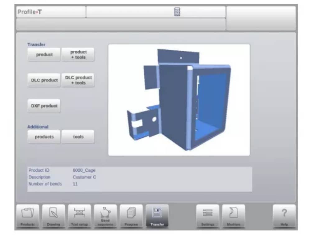
(4) وضع النقل
عندما يتم الانتهاء من تصميم المنتج وإنشاء برنامج CNC، يمكن نقل هذه البيانات في وضع النقل إلى جهاز ذاكرة USB على سبيل المثال.