التصميم الهيكلي للمكابس الهيدروليكية الكبيرة للتشكيل وتحليل العناصر المحدودة
في رحلتي عبر مجال التصنيع، تعمقت في التصميم الهيكلي وتحليل العناصر المحدودة مكابس هيدروليكية كبيرة للتشكيلهذه الآلات القوية ضرورية لإنتاج مكونات عالية القوة، ويتطلب تصميمها دراسة متأنية لعوامل مختلفة لضمان الموثوقية والكفاءة. باستخدام تحليل العناصر المحدودة، تمكنتُ من تحديد نقاط الضعف المحتملة في الهيكل وتحسين الأداء. في هذه المقالة، سأستكشف الجوانب الرئيسية لعمليات التشكيل الكبيرة. مكبس هيدروليكي التصميم الإنشائي ودور تحليل العناصر المحدودة في تعزيز فعاليتها ومتانتها في التطبيقات الصناعية.
1. ما هو مكبس هيدروليكي كبير للتشكيل
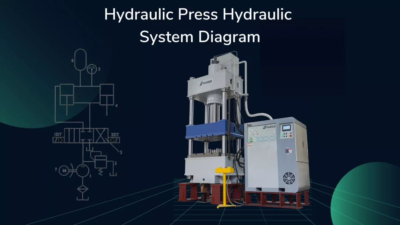
أسطوانة العمل مُشغِّلٌ هامٌّ للآلة الهيدروليكية. تُحوِّل طاقة ضغط السائل إلى طاقة ميكانيكية. تُقسَّم إلى نوعين: مكبس، ومكبس، ومتأرجح، وتلسكوبي، وذلك وفقًا لنوع الهيكل. أسطوانة العمل في آلة التشكيل 200MN مكبس هيدروليكي يعتمد هذا النوع على مكبس ذي بنية بسيطة وسهلة التصنيع. وهو شكل هيكلي شائع الاستخدام في الآلات الهيدروليكية الكبيرة. تُشكل نظرية التصميم التقليدية للمكابس الهيدروليكية الأساس الرئيسي للتصميم الهيكلي لأسطوانة العمل.
تتميز شركة ABAQUS بخبرتها في حل المشكلات المعقدة، وقد طورت برنامجًا رائدًا عالميًا لتحليل العناصر المحدودة. ويُستخدم على نطاق واسع في مجالات الآلات، والصناعات العسكرية، والكيميائية، والسيارات، وغيرها. باستخدام ABAQUS للمحاكاة الرقمية للأسطوانة الهيدروليكية، يُمكن تحديد توزيع إجهاد الأسطوانة العاملة بدقة، وتحليل مدى منطقية تصميمها الهيكلي.
2. التصميم الهيكلي للأسطوانة العاملة
لتوفير الطاقة، وخاصةً استهلاك الطاقة، تستخدم مكبس التشكيل الهيدروليكي الكبير 200MN ست أسطوانات عمل موزعة على ثلاثة صفوف. تولد هذه الأسطوانات الست ضغطًا قدره 200 MN في آنٍ واحد، بينما تولد الأسطوانات الأربع الصغيرة على كلا الجانبين ضغطًا قدره 80 MN، بينما تولد الأسطوانتان الكبيرتان الأوسطتان ضغطًا قدره 120 MN. يمكن لأسطوانات العمل ذات الحركات المختلفة توليد ثلاثة مستويات من الضغط، ويمكن إنتاج أنواع مختلفة من التشكيل لاختيار مستوى الضغط المناسب، مما يوفر التكلفة بشكل كبير. يظهر هيكل وتصميم أسطوانة العمل في الصورتين 1 و2.


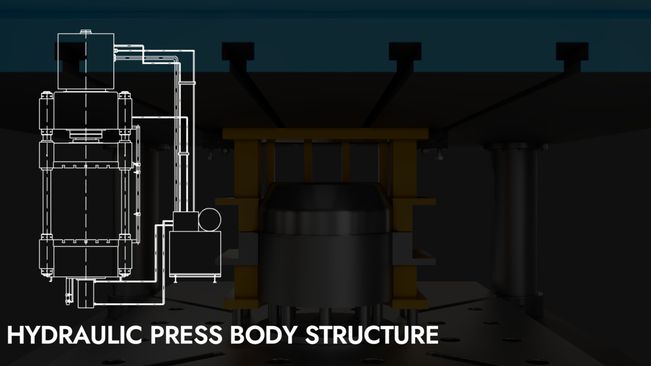
لتحسين عمر أسطوانة العمل، يستخدم التصميم مسمارًا لتثبيت كتلة الأسطوانة على العارضة العلوية مباشرةً، أي باستخدام الدعامة السفلية. هذا لا يُحسّن صلابة ومتانة العارضة العلوية فحسب، بل يُقلل أيضًا من إجهاد جدار أسطوانة العمل.
يعتبر اتصال المفصلة ذات الكرة المفردة مناسبًا للمنزلق والمكابس الأسطوانية الصغيرة الأربعة على الجانب، ويعتبر اتصال المفصلة ذات الكرة المزدوجة أفضل طريقة اتصال للمنزلق والمكابس الأسطوانية الرئيسية الوسطى، كما هو موضح في الصورة 3أ، ب.

عندما يتجاوز ضغط تشغيل أسطوانة العمل 20 ميجا باسكال، يُعتمد بشكل رئيسي على تشكيل الفولاذ الكربوني. تعمل أسطوانة العمل في مكبس التشكيل الهيدروليكي 200MN تحت ضغط عالٍ يبلغ 31.5 ميجا باسكال، وهيكلها كبير، مما يصعب تشكيلها بشكل متكامل. لذلك، تُشكل بلحام الفولاذ 35، وتُعالج وتُقسّى، وتبلغ قوة خضوعها 240 ميجا باسكال.
يتحرك المكبس تردديًا داخل الأسطوانة، ويؤثر بشكل كبير على تآكل غلاف التوجيه والختم، لذا يجب أن يتمتع سطح المكبس بصلابة كافية وتشطيب سطحي جيد. ولتلبية هذا الشرط، يُصنع المكبس عادةً من فولاذ كربوني مطروق عالي الكربون، ويُعالج لتقوية سطحه بعد التشغيل. أما مكبس الآلة الهيدروليكية، فيُصنع من فولاذ 45 مطروق.
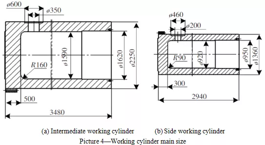
يبلغ الضغط التشغيلي الاسمي لأسطوانة العمل الوسيطة 120MN، ويتم حساب التصميم لمعلماتها الهيكلية على النحو التالي:
وفقًا للضغط الإجمالي الاسمي F(N) الذي يجب أن ينتجه الأسطوانة الهيدروليكية وضغط العمل السائل المحدد P (MPa)، يتم تحديد قطر المكبس D بالصيغة التالية:

من الصيغة (1)، يتم حساب D = 1557.7 مم، وبعد التقريب، يتم أخذ D = 1560 مم، ويتم توصيل القطر الداخلي D1 للأسطوانة الهيدروليكية بالمكبس.
يتعلق الأمر بالفجوة Δt في الجدار الداخلي للأسطوانة، ومن الأفضل أخذ 15 مم وفقًا للتجربة Δt.

وفقًا للصيغة (2) أعلاه، يُحدد القطر الداخلي D1 للأسطوانة الهيدروليكية بـ 1590 مم. ووفقًا للصيغة التجريبية، فإن القطر الخارجي D2 للأسطوانة الهيدروليكية هو:
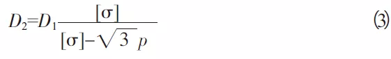
[σ] خذ 120 ميجا باسكال، وفقًا للصيغة أعلاه (2)، أوجد القطر الخارجي D2 للأسطوانة الهيدروليكية وهو 2153 مم، ووفقًا للصيغة:

r1———نصف القطر الداخلي للأسطوانة (مم)
r2———نصف القطر الخارجي للأسطوانة الهيدروليكية (مم)
يتم حسابها بالمعادلة (4)، r2 ≥ 1076.5 مم، خذ D2 = 2 * r2 = 2250 مم.
سمك قاع الأسطوانة: t=(1.5~2)*(r2-r1) (5)
الضغط الاسمي للأسطوانات العاملة الأربع الجانبية هو 80 ميجا باسكال. وبالمثل، يمكن الحصول على المعلمات الهيكلية للأسطوانة الجانبية مبدئيًا كما يلي:
قطر المكبس D = 900 مم، Δt = 10 مم، القطر الداخلي للأسطوانة الهيدروليكية D1 = 920 مم، القطر الخارجي D2 = 1360 مم، سمك قاع الأسطوانة t = 300 مم.
3. المحاكاة العددية وتحليل النتائج للأسطوانة العاملة
حاليًا، تستخدم معظم أسطوانات مكابس التشكيل الهيدروليكي الكبيرة خوارزمية تجريبية لميكانيكا المرونة. بناءً على معايير التصميم الأساسية، تُحدد هذه المعايير بالرجوع إلى البيانات ذات الصلة، ثم يُجرى اختبار المتانة وفقًا للنموذج الميكانيكي المُبسط. ومع ذلك، نظرًا للتركيب المُعقد للأسطوانة الهيدروليكية، يصعب إنشاء نماذج ميكانيكية ورياضية دقيقة، خاصةً في منطقة تركيز الإجهاد. باستخدام طريقة العناصر المحدودة لحساب الأسطوانة الهيدروليكية، يُمكن تحديد توزيع إجهادها بدقة، ومن ثم تحليل منطقية التصميم الهيكلي. الأبعاد الرئيسية لأسطوانة العمل موضحة في الصورة 4.
3.1 إنشاء نموذج العناصر المحدودة
3.1.1 النموذج الهيكلي وتقسيم الوحدة
لجعل حساب أسطوانة العمل أقرب إلى حالة العمل الفعلية، تم تجميع أسطوانات العمل الست مع العارضة العلوية وفقًا للظروف الفعلية. ونظرًا لضعف تأثير تشوه العارضة السفلية على أسطوانة العمل، تم قطع نموذج العمود إلى نصف الارتفاع.
تم اختيار نوع شبكة أسطوانة العمل كوحدة رباعية السطوح C3D4، وتم دمج تفاصيل قاع الأسطوانة، ومدخل الزيت، والفتحة الملولبة، وتقسيمها. تنقسم الأسطوانات الجانبية الأربعة إلى 940,000 وحدة، بينما تنقسم الأسطوانتان الرئيسيتان الأوسطتان إلى 1.2 مليون وحدة.
3.1.2 شروط الحدود
(1) يتم تطبيق ضغط موحد قدره 31.5 ميجا باسكال على السطح الداخلي للجدار الداخلي للأسطوانة العاملة، ويتم توزيع ضغط السائل أسفل الجدار الداخلي للأسطوانة العاملة.
(2) يتم ضبط معامل الاحتكاك μ على 0.1، ويتم تحديد نوع الاتصال كجهة اتصال سطح-سطح قياسية.
(3) اضبط خصائص مادة الأسطوانة العاملة: نسبة بواسون λ هي 0.3، ومعامل المرونة E هو 206000 ميجا باسكال.
(4) يتم شد ذراع كتلة الشعاع العلوي مسبقًا: φ200 مم (10 قطع)، ويتم ضبط قوة الشد المسبق الفردية على 4000 كيلو نيوتن، ويعتمد وضع الشد المسبق على حمل البراغي.
(٥) الشد المسبق لقضيب العمود: يجب أن تكون قوة الشد المسبق معتدلة، لأنها ستؤدي إلى إتلاف قضيب الربط؛ بل على العكس، سيؤدي انخفاض قوة الشد المسبق إلى فتح الجزء الملامس للعارضة والعمود. يُؤخذ الحمل المسبق الإجمالي على أنه ١٫٤ ضعف الضغط الاسمي، ويُعدّ ٢٨٠ ميجا نيوتن الأنسب. من بينها، يُضبط الحمل المسبق الفردي لعشرة قضبان سحب بقطر ٤٠٠ مم على ١٧٥٠٠ كيلو نيوتن؛ ويُضبط الحمل المسبق الفردي لـ ١٢ قضيب سحب بقطر ٣٢٠ مم على ١١٢٠٠ كيلو نيوتن؛ وتُستخدم طريقة التحميل المسبق حمل الترباس.
(6) يتم تطبيق شرط الحدود للمقطع الصلب على المقطع الأوسط من العمود.
ويظهر نموذجها العددي في الصورة رقم 5:

3.2 نتائج المحاكاة والتحليل
بعد حساب النموذج العددي للأسطوانة العاملة، يتم ملاحظة سحابة الإجهاد المكافئة للأسطوانة العاملة وتحليلها.
3.2.1 نتائج المحاكاة وتحليل أسطوانة العمل الرئيسية الوسيطة
تُفتح أسطوانة العمل الرئيسية لمراقبة توزيع الإجهاد الداخلي والخارجي لها. يظهر في الصورة 6 مخطط سحابة الإجهاد المكافئة لأسطوانة العمل الرئيسية الوسيطة.

يظهر تحليل سحابة توزيع الإجهاد المكافئ للأسطوانة العاملة الرئيسية النتائج التالية:
(1) متوسط توزيع الإجهاد المكافئ قرب فتحة التعبئة الداخلية لأسطوانة العمل هو الأعلى، ويتراوح بين 105 و120 ميجا باسكال. أعلى نقطة للإجهاد المكافئ هي 119 ميجا باسكال، ويقع على الجدار الداخلي لأسطوانة العمل قرب الجزء السفلي من فتحة تعبئة السائل.
(2) قيمة الإجهاد المكافئ للجدار الداخلي للجزء الأسطواني ذو الجدار السميك للأسطوانة العاملة مرتفعة نسبيًا، وتوزيع الإجهاد المكافئ موحد نسبيًا بين 95 و115 ميجا باسكال.
(3) قيمة الإجهاد المكافئة في الجزء السفلي من الأسطوانة العاملة منخفضة نسبيًا، ما بين 68 و 85 ميجا باسكال.
(4) يتمتع الجدار الخارجي للجزء الأسطواني ذو الجدار السميك للأسطوانة العاملة بأقل قيمة إجهاد مكافئة، وأقصى قيمة إجهاد مكافئة هي 60MP فقط.
تظهر النتائج العددية أن أقصى إجهاد مكافئ لأسطوانة العمل الرئيسية يحدث بالقرب من منفذ ملء السائل للجدار الداخلي، والقيمة هي 119MP، ومادة أسطوانة العمل 35 فولاذ لها قوة خضوع تبلغ 240MPa بعد المعالجة الحرارية، وعامل الأمان الخاص بها أكبر من 2. ويمكن إثبات ذلك أيضًا أن قوة أسطوانة العمل الرئيسية تلبي متطلبات التصميم.
3.2.2 نتائج محاكاة أسطوانة العمل الجانبية
الصورة 7 توضح سحابة الإجهاد المكافئة للأسطوانة الجانبية.
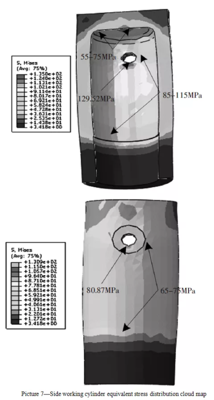
تم إجراء تحليل لسحابة توزيع الإجهاد المكافئ للأسطوانة العاملة الجانبية، وتم الحصول على النتائج التالية:
(1) يتم توليد أقصى قدر من الإجهاد المكافئ بالقرب من منفذ ملء السائل، وقيمة الإجهاد المكافئة له هي 129.5 ميجا باسكال.
(2) يكون توزيع الإجهاد المكافئ للجزء الأسطواني ذو الجدار السميك للجدار الداخلي للأسطوانة موحدًا نسبيًا، وتكون قيمة الإجهاد المكافئ أعلى، وتبلغ قيمة الإجهاد المكافئ 85~110 ميجا باسكال.
(3) الجدار الداخلي للأسطوانة العاملة الجانبية والسطح الخارجي للأسطوانة لهما توزيع إجهاد موحد، والإجهاد المكافئ منخفض، وقيمة الإجهاد المكافئ تكون في الغالب أقل من 75 ميجا باسكال.
مادة أسطوانة العمل الجانبية مصنوعة من فولاذ 35. بعد المعالجة الحرارية، بلغت قوة الخضوع 240 ميجا باسكال. أظهرت نتائج الحسابات العددية أن أقصى إجهاد مكافئ لأسطوانة العمل الجانبية هو 130 ميجا باسكال، ومعامل الأمان محسوب عند 1.85. وبالتالي، فإن قوة أسطوانة العمل الجانبية تلبي متطلبات التصميم.
4. الخاتمة
في هذه الورقة البحثية، استُخدمت نظرية التصميم التقليدية لمكابس هيدروليكية كبيرة للتشكيل بالطرق لحساب أسطوانة العمل لمكبس هيدروليكي للتشكيل بالطرق بقوة 200 ميجا نيوتن باستخدام صيغة رياضية. ثم استُخدم برنامج تحليل العناصر المحدودة ABAQUS لنمذجة مجموعة أسطوانة العمل في ثلاثة أبعاد، ولحساب محاكاة العناصر المحدودة الثابتة. ومن خلال تحليل الإجهاد المكافئ لنتائج محاكاة أسطوانة العمل، استوفت متانة أسطوانة العمل متطلبات التصميم، مما يثبت صحة نتائج حساب الصيغة الرياضية التقليدية وإمكانية تطبيقها في مواصفات تصميم أسطوانة العمل الهيدروليكية.