إعداد آلات القص: نظام التغذية والمقياس الخلفي

باعتباري محترفًا في صناعة التصنيع، غالبًا ما أواجه تعقيدات آلات القص الإعداد، مع التركيز بشكل خاص على نظام التغذية والمقياس الخلفي. يُعد فهم هذه المكونات أمرًا بالغ الأهمية لتحسين الأداء وضمان الدقة في عمليات القطع. في هذه المقالة، سأشارككم رؤى من تجربتي، مسلطًا الضوء على أهمية المحاذاة والتكوين المناسبين. سواء كنتم مشغلين متمرسين أو مبتدئين في هذا المجال، فإن إتقان آلات القص يمكن أن يُحسّن هذا الإعداد الإنتاجية وجودة المنتج بشكل كبير. لنتعمق في أساسيات أنظمة التغذية وتحديد موضع العداد الخلفي.
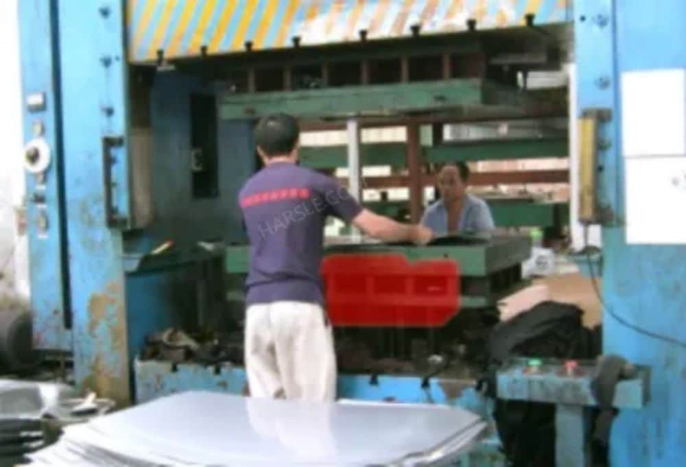
في آلات القص الميكانيكية القديمة، كان ضبط أبعاد القص لآلية تحديد موضع المقياس الخلفي يُجرى يدويًا في الغالب. يتطلب كل معيار إعادة ضبط يدويًا، مما يؤدي إلى انخفاض كفاءة العمل، وإهدار الوقت، ووقوع أخطاء بشرية كبيرة في عملية الضبط. وتبرز هذه المشكلة بشكل خاص عند الحاجة إلى تغييرات متكررة في أبعاد المعالجة.
يُعدّ إعداد آلات القصّ بشكل صحيح أمرًا بالغ الأهمية لتحقيق الدقة والكفاءة في معالجة المعادن. في هذه المقالة، سنستكشف الجوانب الرئيسية للإعداد، مع التركيز على نظام التغذية والمقياس الخلفي. يُعدّ نظام التغذية أساسيًا لتوجيه المواد بدقة إلى آلة القصّ. تضمن آلية التغذية المُحاذية جيدًا تدفقًا ثابتًا للمواد، مما يقلل من خطر الانحشار والقطع الخاطئ.
يتضمن الإعداد الصحيح ضبط سرعة التغذية ومحاذاتها بما يتناسب مع نوع المادة وسمكها، مما يؤثر بشكل كبير على جودة القطع. يُعدّ المقياس الخلفي بالغ الأهمية لتحديد موضع المادة بدقة قبل عملية القطع. يساعد هذا المكون على تحقيق قطع متجانسة ويقلل من الهدر. من المهم معايرة المقياس الخلفي وفقًا للقياسات الصحيحة وفقًا لمواصفات مشروعك. يمكن للفحوصات والتعديلات المنتظمة أن تمنع الأخطاء وتُحسّن الإنتاجية الإجمالية.
إعداد آلات القص
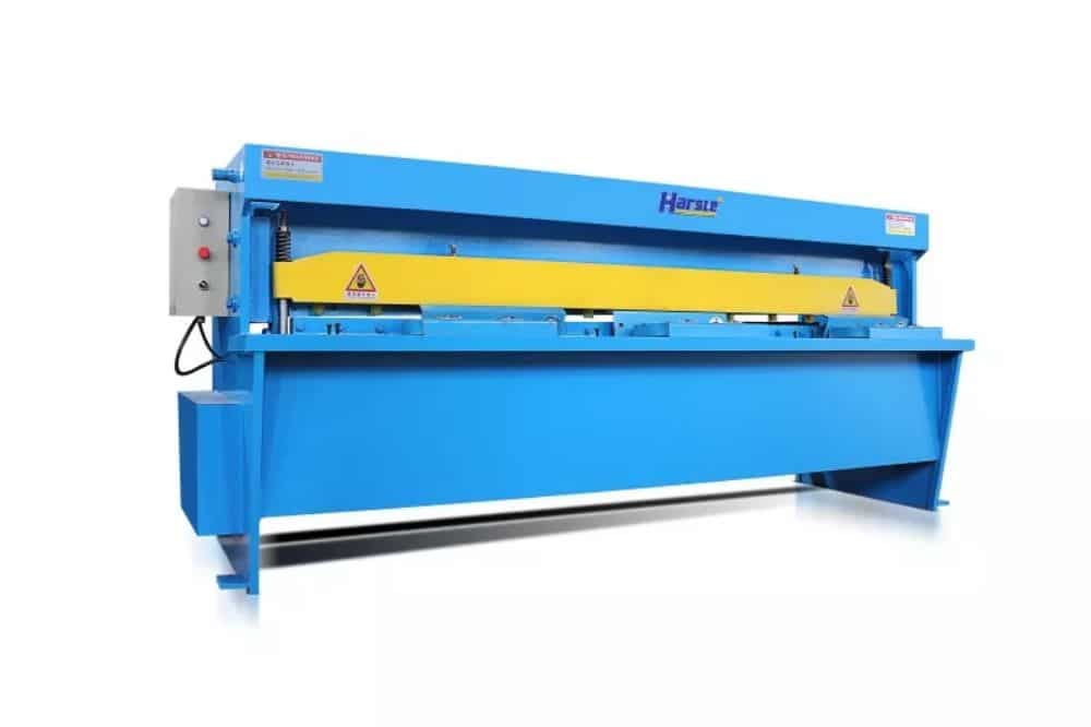
بفضل التحسينات التدريجية، صُممت الإصدارات الأحدث من جهاز تحديد موضع المقياس الخلفي لآلة القص ليتم تشغيله عن طريق تدوير مقبض متصل ببرغي توصيل. يُحرك هذا الدوران كتلة الانزلاق ولوحة المقياس المتصلة، مما يسمح بتعديل موضع اللوحة. كبديل، تُركّب آلية المقياس الخلفي في بعض الآلات على جسم القص، وتتحرك مع الشفرة. ومع ذلك، يُواجه هذا الإعداد مشاكل مثل ضعف القوة الميكانيكية، وقابلية التلف، وانخفاض دقة ضبط الحجم، ومسافة الضبط المحدودة.
عادةً ما تستخدم آلية التغذية التلقائية لآلة القص قضيبًا مُدارًا لنقل المواد. تُوضع الصفائح المعدنية على القضيب المُدار وتتحرك للأمام مع دورانه. ومع ذلك، نظرًا للمسافة بين الأسطوانة المُدارة وآلة القص، عند خروج طرف الصفائح المعدنية من الأسطوانة المُدارة، تظل الصفائح المعدنية قادرة على تحقيق أبعاد القطع، لكنها لا تستطيع التحرك للأمام. في هذه المرحلة، يلزم الدفع اليدوي لإكمال عملية القص. تفتقر هذه الآلة إلى مستوى عالٍ من الدقة وسهولة التشغيل.

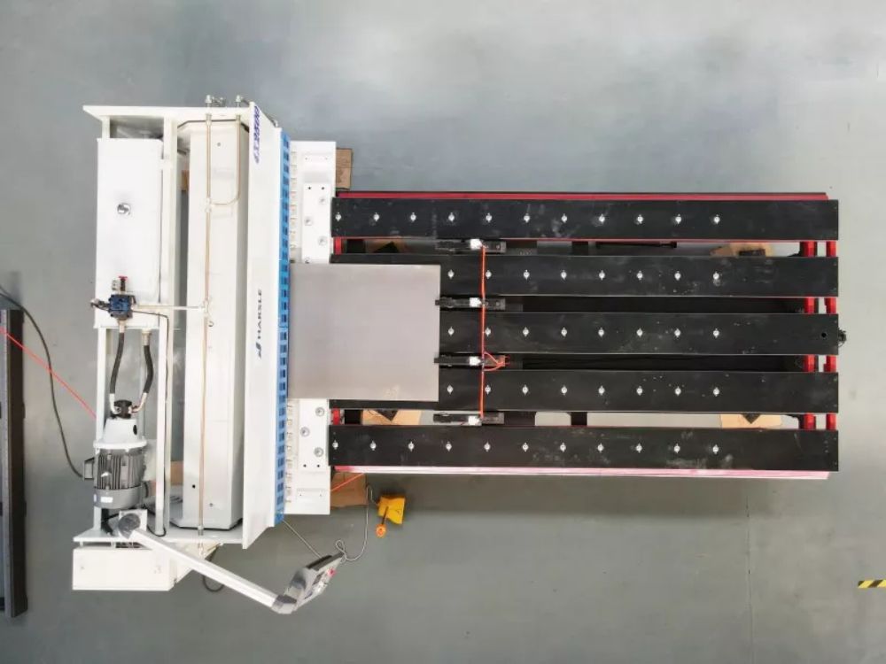
أحدث التطورات في أجهزة التغذية وتحديد موضع المقياس الخلفي لآلات القص أتاحت تحكمًا آليًا دقيقًا في الموضع. يتميز الجهاز بهيكل بسيط، وسهولة في التشغيل، ودقة عالية في القطع. يتكون الجهاز بالكامل من آلية لتحديد موضع المقياس الخلفي، وآلية تغذية، ونظام تحكم. وتكمن الميزة المميزة في آلية تحديد موضع المقياس الخلفي، التي تتضمن مكون نقل حركة أفقيًا على دعامة.
يتضمن مُكوّن ناقل الحركة آلية رفع، تتصل بإطار دعم يدور حول محور مفصلي. الإطار الداعم مُجهّز بلوحة قياس، تتضمن مفتاح تحديد موضع واحد على الأقل. تتكون آلية التغذية من مُكوّن تغذية يُدار بواسطة بكرة وآلية تغذية دفع قابلة للتحريك رأسيًا وأفقيًا. تقع آلية التغذية بالدفع فوق مُكوّن التغذية المُدار بواسطة بكرة.
يتضمن نظام التغذية برغيًا رصاصيًا مزودًا بصامولة، وإطار توجيه، ومزلاجًا. يُثبَّت أحد طرفي الرف، المزود بلوحة دفع، على إطار التوجيه، ويمكن تحريكه لأعلى ولأسفل باستخدام الصامولة. يتشابك الرف مع ترس ويتحرك أفقيًا مدفوعًا به. يحتوي المزلاج على عمود تروس يحتوي على تروس، وعجلة سلسلة تُدار بواسطة آلية دفع، ودعامات ثلاثية القوائم متناظرة على طرفي عمود التروس.
يتصل أحد أركان دعامة الحامل الثلاثي بعمود التروس، ويتصل ركن آخر بأسطوانة الضغط لوحدة التغذية المُدارة بالأسطوانة، بينما تعمل الزاوية الثالثة كمحور، حيث تتصل بإطار الأسطوانة. كما تتضمن دعامة لدعم آلية التغذية، حيث يُثبت قاعها بمفصلة على إطار الأسطوانة. يقع أحد ذراعي الدعامة بين آلة القص ووحدة التغذية المُدارة بالأسطوانة، بينما يقع ذراع الدعم الآخر بين بكرتي النقل ويواجه رف آلية التغذية الدافعة.
فيما يتعلق بجهاز تحديد موضع المقياس الخلفي، فهو يتكون بشكل أساسي من برغي توصيل، وصامولة، ولوح ثابت متصل بالصامولة المتحركة. تُركّب قضبان انزلاق آلية الرفع بشكل متماثل على اللوح الثابت، ويُركّب إطار الرفع على قضبان الانزلاق. يحتوي الجزء العلوي من قضبان الانزلاق على محامل، مع عمود هزاز مُركّب على المحامل.
يحتوي عمود التأرجح على عجلة سلسلة تُدار بواسطة آلية دفع، وهو متصل بأذرع تأرجح من كلا الطرفين. يتصل الطرف الآخر لأذرع التأرجح بإطار الرفع، المثبت من الأسفل بمفصلة على إطار الدعم. تجهيز آلات القص. يحتوي أحد جانبي إطار الدعم على لوحة قياس مزودة بمفتاحي تثبيت، بينما يحتوي الجانب الآخر على نوابض شد مثبتة على كلا الطرفين، تربط بين إطار الدعم وإطار الرفع.

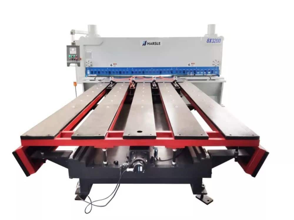
يتميز نظام التغذية وجهاز تحديد موضع القياس الخلفي لآلات القص بهيكل بسيط، ويمكن استخدامه مع آلة القص. يتميز النظام بأتمتة عالية، وسهولة في التشغيل، وتنسيق مع نظام التحكم. ويحقق التغذية التلقائية وضبط موضع لوحة التوقف، دون الحاجة إلى التشغيل اليدوي.
ضمن نطاق أبعاد الصفائح المعدنية المناسبة للقص، يُمكن تغذية الصفائح المعدنية تلقائيًا إلى آلة القص. تتميز بكفاءة عمل عالية، واستخدام عالٍ للصفائح المعدنية، وعملية قص آمنة، وانخفاض في احتمالية الحوادث. كما تتميز بانخفاض تكاليف العمالة. تُدخل أبعاد القص في نظام التحكم، الذي يُمكّن من تعديل التغييرات تلقائيًا حسب الحاجة. يُسهّل وضع التوقف الخلفي عملية القص ويُحسّن دقة أبعاد القص.