Schéma du système hydraulique d'une machine hydraulique

D'après mon expérience de travail avec machines hydrauliques, comprendre le système hydraulique Le schéma est essentiel à l'efficacité de l'exploitation et de la maintenance. Il représente visuellement les composants du système et leurs interconnexions, aidant les opérateurs à résoudre les problèmes et à optimiser les performances. Au fil des ans, j'ai appris à interpréter ces schémas, ce qui a grandement amélioré ma capacité à diagnostiquer les problèmes et à mettre en œuvre des solutions. Dans cet article, j'explorerai les éléments clés du schéma du système hydraulique d'une machine hydraulique, fournissant des informations qui aideront les opérateurs, novices comme expérimentés, à mieux comprendre et utiliser les systèmes hydrauliques.
1. Sélectionnez le circuit de base
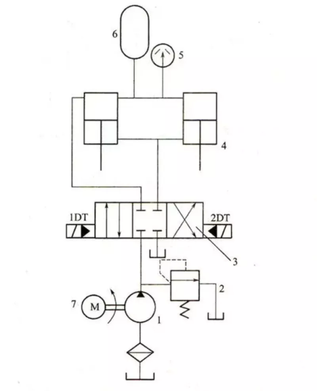
Boucle de régulation de vitesse : Le système hydraulique étant de faible puissance et soumis à une charge positive, la boucle de régulation de vitesse du papillon d'admission d'huile est sélectionnée. Pour une fluidité optimale à basse vitesse et une bonne charge, la vitesse de la vanne de régulation de vitesse et la contre-pression du circuit hydraulique peuvent être sélectionnées.
●Circuit d'alimentation en huile de la pompe : Étant donné que la différence entre la vitesse de travail et la vitesse de déplacement rapide est très différente, la double pompe est utilisée pour l'alimentation en huile.
Circuit de commutation de vitesse et circuit rapide : La différence entre la vitesse de travail et la vitesse d'avance rapide étant importante, le circuit de commutation commandé par la vanne de course est sélectionné pour une commutation fluide. Le mouvement rapide est obtenu par un circuit différentiel.
Circuit de commutation : Pour un fonctionnement fluide, utilisez un distributeur électrohydraulique. Pour obtenir l'arrêt neutre et la connexion différentielle du vérin hydraulique, utilisez un distributeur à cinq voies et trois positions.
●Circuit de contrôle de pression : l'utilisation du circuit de charge basse tension de type vanne d'inversion réduit la consommation d'énergie et la structure est relativement simple.
2. Sélection du circuit hydraulique
Des ajustements, des modifications et des fusions sont nécessaires à la synthèse de la boucle de base sélectionnée.
●Pour éviter que les conduites d'admission et de retour ne soient percées pendant l'alimentation du travail et pour accéder au clapet anti-retour.
Pour obtenir une avance rapide différentielle, une vanne de séquence de commande hydraulique doit être installée sur la conduite de retour pour empêcher l'huile de refluer vers le réservoir.
Le principe de fonctionnement du système hydraulique complet après la fusion est le suivant :