


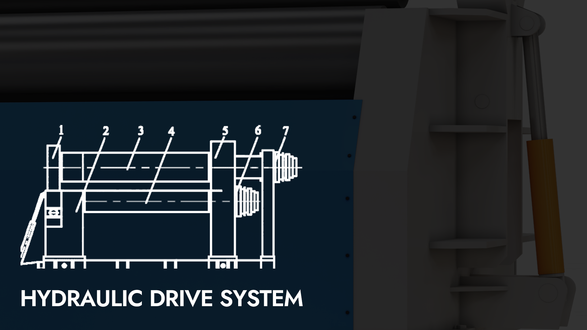
Système d'entraînement hydraulique pour rouleau de travail d'une lamineuse de tôles à trois rouleaux
En travaillant sur des laminoirs à tôles à trois rouleaux, j'ai pu apprécier le rôle crucial du système d'entraînement hydraulique du rouleau de travail. Ce système assure non seulement un contrôle précis et une efficacité optimale pendant le laminage, mais influence également significativement les performances globales de la machine. Comprendre les subtilités du système d'entraînement hydraulique permet d'optimiser les opérations et de réduire les coûts de maintenance. Dans cet article, j'explorerai les composants et les fonctionnalités du système d'entraînement hydraulique du rouleau de travail, en partageant des informations susceptibles d'améliorer les performances et la fiabilité des applications de laminage de tôles.
Le machine à rouler les plaques à trois rouleaux Ce procédé repose sur le principe de la rotation de trois points formant un cercle. Le mouvement rotatif du rouleau de travail et l'ajustement de sa position relative permettent de produire une déformation plastique continue de la tôle et de la cintrer en forme cylindrique, conique ou arquée. Cet article, basé sur une analyse détaillée du système d'entraînement du moteur hydraulique du rouleau de travail, explique la cause de la défaillance et propose une solution raisonnable et réalisable.
1. Principe de fonctionnement du système d'entraînement hydraulique
La plaque inclinable à trois rouleaux machine à rouler La machine est composée d'un mécanisme à tête inversée, d'un châssis gauche, d'un rouleau de travail supérieur, de deux rouleaux de travail inférieurs, d'un châssis droit, d'un moteur hydraulique entraîné par un rouleau de travail inférieur et d'un moteur hydraulique entraîné par un rouleau de travail supérieur, etc., comme illustré à la figure 1. Les châssis gauche et droit sont montés sur une base soudée et reliés par des bielles pour renforcer la rigidité de l'ensemble. Le rouleau de travail supérieur est fixe, tandis que les deux rouleaux de travail inférieurs peuvent se déplacer verticalement le long des rainures de guidage obliques situées respectivement sur les châssis gauche et droit. Le mouvement rotatif des rouleaux de travail constitue le principal système de transmission, installé sur le côté du châssis droit, tandis que le mécanisme à tête inversée est installé sur le côté du châssis gauche. Les mouvements d'inclinaison et de réinitialisation sont contrôlés par le vérin à tête inversée.
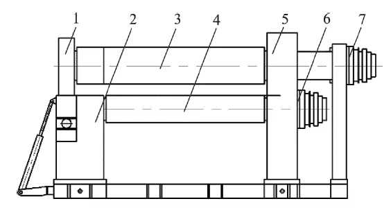
5. Cadre droit 6. Moteur hydraulique d'entraînement du rouleau de travail inférieur 7. Moteur hydraulique d'entraînement du rouleau de travail supérieur
Figure 1 — Schéma de principe d'une machine à rouler les plaques inclinées vers le bas
Le rouleau de travail supérieur de la lamineuse à trois rouleaux est entraîné par un moteur hydraulique via un réducteur planétaire, tandis que les deux rouleaux de travail inférieurs (gauche et droit) sont entraînés directement par le moteur hydraulique. Le schéma de principe du système d'entraînement hydraulique du rouleau de travail est illustré à la figure 2. Ce système comprend trois circuits hydrauliques indépendants : le rouleau supérieur, le rouleau inférieur gauche et le rouleau inférieur droit.
Afin de garantir la qualité des produits traités par la lamineuse de tôles, la vitesse de travail des trois rouleaux de travail (supérieur, inférieur gauche et inférieur droit) doit être stable et réglable, sans aucune influence d'autres mécanismes, afin d'assurer une distribution fluide de la tôle. Le rouleau de travail supérieur et les deux rouleaux de travail inférieurs constituent les principaux rouleaux d'entraînement. Ils assurent non seulement la rotation avant et arrière, mais fournissent également le couple d'enroulement nécessaire au laminage de la tôle grâce à la pression exercée par ces deux rouleaux. La tôle est ainsi laminée en formes cylindriques, coniques ou autres. À cet effet, trois circuits hydrauliques spécifiques sont prévus : chaque rouleau de travail est alimenté par un ensemble de sources d'huile hydraulique spécifiques, formant ainsi un circuit hydraulique indépendant des autres mécanismes, garantissant ainsi une vitesse stable et réglable.
Sur la figure 2, le réservoir d'huile stocke l'huile hydraulique, dissipe la chaleur et élimine les impuretés dans l'huile précipitée. Les rouleaux d'aspiration supérieur, inférieur gauche et inférieur droit sont des filtres grossiers garantissant la propreté de l'huile entrant dans les trois circuits hydrauliques indépendants. La pompe hydraulique et son moteur d'entraînement alimentent les circuits hydrauliques des rouleaux supérieur, inférieur gauche et inférieur droit. Les manomètres indiquent respectivement la pression de service aux trois sorties de pompe hydraulique. La soupape de décharge électromagnétique contrôle respectivement le moteur hydraulique du rouleau supérieur et la pression hydraulique du rouleau inférieur gauche. La pression de service du moteur et du moteur hydraulique du rouleau inférieur droit dispose également d'une fonction de décharge pour réaliser une régulation de pression en deux étapes. Lorsque le rouleau de travail est à l'arrêt, la décharge est utilisée pour réaliser des économies d'énergie. La vanne directionnelle électrohydraulique contrôle les moteurs des rouleaux supérieur et inférieur gauche. La marche avant, arrière et l'arrêt du moteur et du moteur du rouleau inférieur droit. Le groupe de vannes tampon limite la pression de service maximale de chaque côté des rouleaux supérieur, inférieur gauche et inférieur droit. Le moteur d'entraînement du rouleau de travail est un moteur quantitatif bidirectionnel, qui peut être en marche avant et en marche arrière pour réaliser le mouvement bidirectionnel de la plaque.
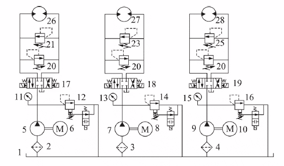
Pompe hydraulique 6/8/10. Moteur d'entraînement 11/13/15. Manomètre 12/14/16. Soupape de décharge électromagnétique 17/18/19. Distributeur électrohydraulique 20/21/22/23/24/25. Groupe de soupapes tampon 26. Moteur hydraulique du rouleau supérieur 27.
Moteur hydraulique du rouleau inférieur gauche 28. Moteur hydraulique du rouleau inférieur droit
Figure 2 — Schéma de principe de l'entraînement hydraulique du rouleau de travail de la cintreuse de tôles
2. Améliorer la conception du système
Le circuit hydraulique du rouleau de travail ci-dessus est utilisé comme exemple d'analyse. Lorsque le moteur hydraulique entraîne la rotation du rouleau supérieur, si le distributeur électrohydraulique est brusquement commuté en position neutre ou si le sens de rotation est inversé, un choc important se produit, affectant la durée de vie du moteur hydraulique 26 du rouleau supérieur. Sur la figure 2, le distributeur électrohydraulique 17 a une fonction centrale de type O. Lors de la commutation du distributeur électrohydraulique 17 en position neutre pour freiner le rouleau supérieur, l'entrée et la sortie du moteur hydraulique 26 sont toutes deux fermées. Le distributeur électrohydraulique 17 est fermé en position neutre.
Sous l'effet de l'inertie, une chambre haute pression se forme à la sortie d'huile du moteur hydraulique 26 et une chambre à vide à l'entrée d'huile. La pression côté sortie du moteur hydraulique 26 augmente, générant ainsi une force de freinage. La soupape tampon située à cet endroit limite la pression et réduit le choc hydraulique. Après ouverture de la soupape tampon 20 (ou 21), l'huile côté haute pression peut être directement évacuée dans la conduite côté basse pression au niveau de la chambre à vide, puis pénétrer dans l'entrée d'huile du moteur pour réduire la dépression. Cette méthode de raccordement de la soupape tampon est appelée remplissage d'huile direct, mais son inconvénient est qu'elle ne permet pas de compenser complètement la quantité d'huile requise par l'entrée d'huile. De plus, en raison des fuites internes du moteur hydraulique et du distributeur électrohydraulique (ce dernier étant à tiroir), l'entrée d'huile n'est pas raccordée à la conduite basse pression ni au réservoir d'huile et ne peut donc pas être alimentée en huile externe. Par conséquent, le remplissage en huile est insuffisant. Ce manque d'huile maintient l'entrée d'huile sous vide pendant une longue période, ce qui provoque une cavitation et réduit considérablement la durée de vie du moteur hydraulique.
Afin de résoudre complètement le phénomène de vide et de cavitation à l'entrée d'huile du moteur hydraulique, une solution améliorée pour l'utilisation couplée de la soupape de charge unidirectionnelle et de la soupape tampon est proposée : l'huile est entièrement fournie à l'entrée d'huile du moteur hydraulique par l'intermédiaire de la soupape unidirectionnelle, pour éviter le phénomène de vide ; la soupape tampon peut non seulement réduire le choc hydraulique causé par la soupape directionnelle électrohydraulique en position neutre, mais aussi permettre au moteur hydraulique de freiner en douceur ; la soupape directionnelle électrohydraulique adopte une fonction neutre de type M. Le schéma d'amélioration est illustré à la figure 3.
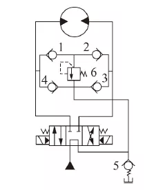
Figure 3 — Diagramme schématique du programme d'amélioration
Dans le plan d'amélioration, la vanne tampon 6 et les quatre clapets anti-retour forment un circuit d'alimentation en huile tampon en pont complet. Le clapet anti-retour tampon 1 ou 2 assure le passage de l'huile haute pression des chambres gauche et droite à travers la vanne tampon 6, tandis que le retour d'huile est bloqué par le clapet anti-retour tampon côté basse pression, empêchant ainsi le passage de l'huile côté haute pression. Le clapet anti-retour tampon s'écoule vers la conduite basse pression de ce côté. Le clapet anti-retour de charge (3 ou 4) assure la charge bidirectionnelle (moteur hydraulique en marche avant et arrière, et deux clapets anti-retour de charge doivent être réglés) pour réalimenter la conduite côté basse pression. Sa pression de charge est réglée par la vanne de contre-pression 5, généralement entre 0,3 et 0,5 MPa. Grâce à cette contre-pression, ce circuit d'huile assure un réapprovisionnement complet en huile. L'huile haute pression générée par l'inertie du moteur hydraulique traverse le clapet anti-retour 1 ou 2, puis est soumise à un débordement limitant la pression par la vanne tampon 6. La pression de tarage de la vanne tampon 6 limite la pression maximale à la sortie du moteur hydraulique. L'amplitude de cette pression de tarage détermine le couple de freinage du moteur. Cette solution améliorée permet non seulement de jouer un rôle tampon, mais aussi d'assurer un apport d'huile complet.


