


Maîtriser la presse hydraulique : principes d'installation et de fonctionnement

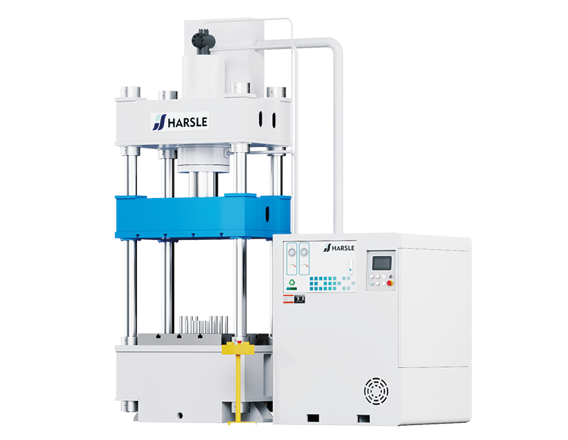
UN presse hydraulique Il s'agit d'une machine qui utilise la force hydraulique pour comprimer ou façonner des matériaux, ce qui la rend essentielle dans diverses applications industrielles. Comprendre son installation et ses principes de fonctionnement est essentiel pour une utilisation et une maintenance efficaces.
1. Principe de fonctionnement de presse hydraulique
Le principe de fonctionnement d'une presse hydraulique repose sur un mécanisme à vilebrequin et bielle. Le moteur entraîne le volant d'inertie, qui transmet la puissance via l'arbre et le pignon au grand engrenage. Ce dernier, relié par un embrayage, fait tourner le vilebrequin, qui entraîne à son tour la bielle pour déplacer le coulisseau. La cadence de course et la courbe de déplacement du coulisseau restent constantes. Structurellement, la presse se compose de quatre sections principales : le bâti, la partie travaillante, la partie de commande et la partie de transmission, tous les composants étant montés sur le bâti. Les presses poinçonneuses hydrauliques permettent des opérations d'emboutissage de tôles polyvalentes, notamment le poinçonnage, le pliage et l'emboutissage superficiel.
2. Principaux composants de la presse hydraulique
⑴Partie du lit : Le lit et la table de travail sont des pièces en fonte
⑵Embrayage : Lorsque la presse est au repos, la came du manipulateur verrouille l'extrémité de la clavette, garantissant ainsi l'engagement complet du bloc croissant de la pièce active dans la rainure semi-circulaire du vilebrequin. Dans cet état, le vilebrequin tourne au ralenti tandis que le coulisseau reste au point mort haut. En fonctionnement, la came du manipulateur tourne légèrement, libérant la clavette. Sous l'effet du ressort, la clavette pivote d'environ 45°, permettant à l'arrière de la pièce active de s'engager dans l'une des trois rainures circulaires du manchon central. L'embrayage s'engage alors, transmettant le mouvement du volant au vilebrequin, entraînant le coulisseau dans sa course de va-et-vient.
⑶Curseur : Un dispositif de sécurité de type pédale de pression est situé sous le bol à billes, en contact avec la tête sphérique de la vis de réglage, afin de garantir que la presse ne soit pas endommagée en cas de surcharge. Ouvrir le couvercle carré à l'avant pour changer le dispositif de sécurité.
⑷Bande de frein : Une bande de frein excentrique est installée à l'extrémité gauche du vilebrequin. Lorsque l'embrayage est débrayé, elle neutralise l'inertie du mouvement alternatif du coulisseau et assure l'arrêt du vilebrequin au point mort haut.
⑸Manipulateur : Mécanisme qui contrôle l'embrayage et le débrayage lors de son utilisation. Changez la position de connexion du levier du manipulateur pour obtenir deux actions : une course unique et une course continue.
3. Installation de la presse hydraulique
⑴Une fois le perforateur hydraulique nivelé, installez les boulons d'ancrage et remplissez le béton. Une fois le béton complètement solidifié, serrez uniformément les écrous des boulons d'ancrage, puis utilisez un niveau pour recalibrer l'établi. Le fil de terre doit être correctement connecté.
⑵Le poinçon hydraulique doit être complètement solidifié avant de pouvoir commencer à fonctionner.
⑶Une fois le poinçon hydraulique installé, utilisez du kérosène pour éliminer la graisse antirouille présente sur sa surface. Lors du nettoyage, veillez à ne pas endommager la surface peinte. Nettoyez également les orifices, les canaux et les traces d'huile et maintenez-les propres. N'utilisez pas de métal ni de toile émeri pour frotter.
4. Principe de l'embrayage à poinçon :
Il convertit un mouvement circulaire en mouvement linéaire. Le moteur principal génère de la puissance pour entraîner le volant d'inertie, tandis que l'embrayage entraîne l'engrenage, le vilebrequin (ou engrenage excentrique), la bielle, etc., pour assurer le mouvement linéaire du coulisseau, du moteur principal à la bielle. Pour un mouvement circulaire, il existe un point de transition entre la bielle et le coulisseau. Sa conception repose sur deux mécanismes : l'un à billes et l'autre à goupille (cylindrique), qui convertissent le mouvement circulaire en mouvement linéaire du coulisseau.
Russia-Customer-Feedback-5.jpg)
Russia-Customer-Feedback-4.jpg)
Russia-Customer-Feedback.jpg)


