Panoramica della pressa a manovella: struttura e principi di funzionamento

La pressa a manovella è un tipo di pressa meccanica e può anche essere chiamato un pressa a manovellaIl suo principio di funzionamento è un meccanismo a manovella-cursore.
1. Principio di funzionamento e struttura
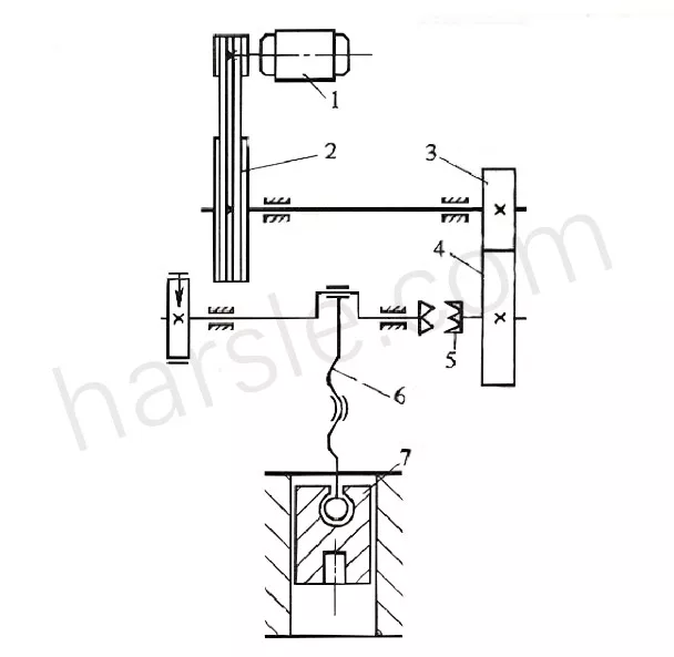
La figura 1 è un disegno schematico, la figura 2 è un diagramma del movimento.
Il suo principio di funzionamento è il seguente: motore
⑴ Trasmettere il movimento alla puleggia grande attraverso la cinghia trapezoidale
⑵ Dopo il pignone
⑶ Grande ingranaggio
⑷ Passa alla frizione
⑸ La frizione 5 trasmette il moto all'albero motore
⑹ L'estremità superiore della biella è montata sull'albero motore, mentre l'estremità inferiore è collegata al cursore.
⑺ Il movimento rotatorio dell'albero motore viene convertito in un movimento alternato lineare del cursore. Lo stampo superiore dello stampo è montato sul cursore, mentre lo stampo inferiore è montato sul tavolo. Pertanto, quando il materiale viene posizionato tra lo stampo superiore e quello inferiore, è possibile eseguire la punzonatura e altri processi di stampaggio. A seconda delle esigenze del processo produttivo, il cursore a volte si muove e a volte si ferma.
Pertanto, oltre alla frizione, all'estremità dell'albero motore è installato anche un freno, e la pressa a manovella funziona per un breve periodo di tempo durante l'intero ciclo di lavoro, ovvero quando il carico è in funzione. Il tempo è breve e la maggior parte del tempo è senza carico morto. Per uniformare il carico del motore e utilizzare l'energia in modo efficiente, è installato un volano. La puleggia grande 2 funge da volano.
Come si può vedere dal principio di funzionamento sopra descritto, la pressa a manovella è composta dalle seguenti parti:
(1) Meccanismo di funzionamento: meccanismo del cursore della manovella costituito da albero motore, biella, cursore e altre parti.
(2) Sistema di trasmissione: comprendente la trasmissione ad ingranaggi, la trasmissione a cinghia e altri meccanismi.
(3) Sistema operativo: come frizioni e freni.
(4) Sistema energetico: come motore elettrico, volano.
(5) Parti di supporto: come la fusoliera.
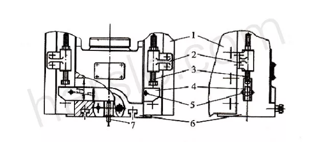
2. La struttura comune sul cursore della manovella
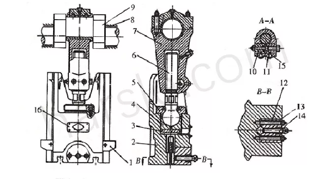
⑴Dispositivo di regolazione dell'altezza del modulo
Per adattarsi a installazioni di stampi con diverse altezze di chiusura, è presente un dispositivo per la regolazione dell'altezza della pressa nel cursore dell'albero motore della pressa. Come mostrato in figura, lo schema del meccanismo del cursore della manovella del freno. Per la regolazione, allentare innanzitutto il filo superiore 15, quindi allentare la vite di bloccaggio 10 e infine ruotare l'asta di regolazione 6, in modo che la lunghezza della vite di collegamento sia maggiore o minore, in modo da ridurre o aumentare l'altezza dello stampo.
Dopo l'installazione e la messa a punto dello stampo, la vite 10 e il filo superiore 15 devono essere bloccati uno dopo l'altro per impedire il ritorno della biella. Per presse di grandi e medie dimensioni, la vite di regolazione viene ruotata da un motore separato tramite un meccanismo a ingranaggi o a turbina.
⑵Dispositivo pezzo superiore
La pressa è generalmente dotata di un dispositivo di bloccaggio superiore sull'elemento scorrevole per lo stampo superiore. Il dispositivo di bloccaggio superiore è rigido e pneumatico, e di seguito viene descritto solo il dispositivo di bloccaggio superiore rigido.
Come mostrato, il gruppo del pezzo superiore è costituito da una guida di battuta 4 che passa attraverso il cursore e da una vite di arresto 3 fissata alla fusoliera. Quando il cursore viene premuto verso il basso, a causa dell'azione del pezzo in lavorazione, l'asta di espulsione 7 dello stampo superiore viene sollevata nel cursore tramite la barra trasversale. Quando il cursore torna al punto morto superiore, le due estremità della barra di battuta vengono bloccate dalla vite a testa della fusoliera, il cursore continua a salire e la barra di battuta si sposta verso il basso rispetto al cursore, spingendo la parte superiore nello stampo superiore. Il pezzo in lavorazione dell'asta viene espulso.
La corsa massima di lavoro della barra di battuta è Hh. Se la vite a testa cilindrica viene toccata troppo presto, si verificherà un guasto dell'attrezzatura. Pertanto, quando si utilizza la vite a testa cilindrica, il cursore deve trovarsi al punto morto superiore.
Il dispositivo con parte superiore rigida ha una struttura semplice, un funzionamento affidabile e un'ampia gamma di applicazioni. Tuttavia, la forza del materiale superiore e la sua posizione non possono essere regolate arbitrariamente.