


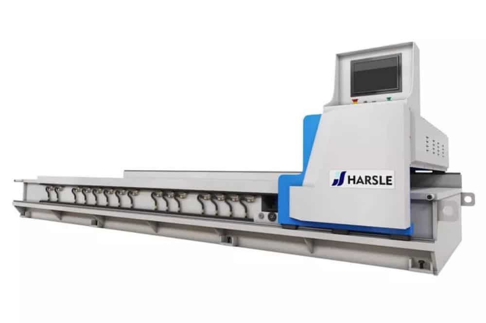
Quando lavoro con progetti complessi di fabbricazione di metalli, Macchine per scanalature a V per lamiere diventano spesso una parte cruciale del processo. Queste macchine sono progettate per creare scanalature profonde e strette nei pannelli di lamiera, consentendo di ottenere piegature pulite e precise e pieghe angolari. Se vi state chiedendo perché la scanalatura sia necessaria quando esistono presse piegatrici o piegatrici, questa guida vi illustrerà il ruolo unico che queste macchine svolgono nel migliorare la precisione di piegatura, l'estetica visiva e l'efficienza complessiva della fabbricazione.
Con il rapido progresso del settore industriale cinese, la domanda di maggiore precisione nella piegatura della lamiera continua a crescere. Per soddisfare standard estetici e funzionali sempre più rigorosi, molte aziende ora incorporano pre-scanalatura nei loro processi di piegatura. Il processo di scanalatura, in particolare le scanalature a V e a U, è diventato essenziale per ottenere curve nette e finiture pulite. Con l'evoluzione degli standard di progettazione, sempre più settori, compresi quelli high-tech, stanno adottando questa tecnica. I principali settori di applicazione includono l'industria leggera, gli elettrodomestici, l'automotive, la lavorazione dell'acciaio inossidabile, l'architettura, gli utensili da cucina, la ventilazione, il settore aerospaziale, gli ascensori e altro ancora. La scanalatura supporta anche la smussatura dei bordi, il taglio e i trattamenti superficiali personalizzati per una migliore qualità del prodotto.

1. Scopo e utilizzo della progettazione e produzione di macchine scanalatrici
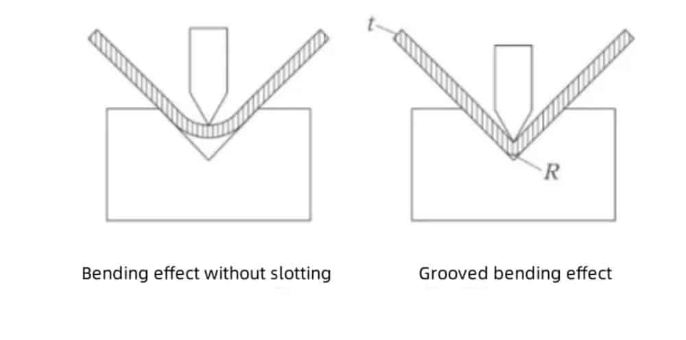
1.1 Dopo il macchina per scanalature Eseguendo scanalature a V sulla lamiera, l'angolo di piegatura della lamiera sarà facile da formare durante il processo di piegatura e l'angolo R dopo la formatura sarà molto piccolo. Il pezzo non si torce o si deforma facilmente e la rettilineità, l'angolazione, la precisione dimensionale e l'aspetto del pezzo dopo la piegatura e la formatura possono garantire buoni risultati.
1.2 Dopo che la lamiera è stata scanalata a V dalla macchina scanalatrice, la forza di piegatura richiesta sarà ridotta, in modo che lamiere lunghe e spesse possano essere piegate su una macchina piegatrice di tonnellaggio inferiore. Ciò ridurrà il consumo energetico della macchina.
1.3 La macchina scanalatrice può anche eseguire lavorazioni di marcatura preposizionate sulla lamiera, in modo che il pezzo in lavorazione possa garantire un'elevata precisione nelle dimensioni del bordo di piegatura durante il processo di piegatura.
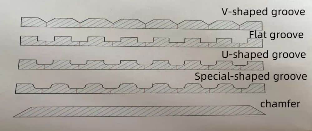
1.4 In base ai requisiti speciali del processo di scanalatura, la macchina scanalatrice può elaborare scanalature a forma di U sulla superficie di alcuni fogli, in modo che la superficie lavorata possa essere bella, antiscivolo e pratica per la giunzione.
2. Classificazione e modalità di lavorazione delle macchine scanalatrici
2.1.Le macchine per scanalature si dividono in due categorie: macchine per scanalature discrete e macchine per scanalature a portale (orizzontali).
2.2. Le scanalatrici verticali includono macchine per scanalatura con portautensile singolo e doppio. La macchina per scanalatura post-scanalatura con portautensile singolo adotta la scanalatura con taglio destro. La macchina per scanalatura con portautensile doppio può essere suddivisa in scanalatura con taglio destro e scanalatura con taglio sinistro. Può anche essere utilizzata con due portautensili per eseguire scanalature con taglio destro e lavorazioni con taglio sinistro contemporaneamente. Può anche utilizzare la scanalatura bidirezionale avanti e indietro.
2.3. Le scanalatrici a portale possono essere suddivise in scanalatrici a trasmissione singola e scanalatrici a trasmissione doppia. Entrambe le scanalatrici utilizzano la modalità di lavorazione con taglio destrorso.
Macchina per scanalatura a portale ad alta velocità

Macchina per scanalature verticali ad alta velocità con doppio coltello

Macchina per scanalature verticali ad alta velocità con lama singola
3. Categorie di compressione e serraggio delle macchine scanalatrici
3.1.Le macchine scanalatrici verticali possono essere suddivise in dispositivi idraulici, dispositivi pneumatici e dispositivi di miscelazione gas-liquido.
3.2. La macchina per scanalatura a portale, come la macchina per scanalatura verticale, è anch'essa divisa in dispositivo idraulico, dispositivo pneumatico e dispositivo di miscelazione gas-liquido.
4. La struttura della macchina per scanalature a V CNC
4.1. Le macchine per scanalatura verticale possono essere suddivise in due tipologie: saldatura a corpo intero e connessioni a vite. Poiché le connessioni a vite causano allentamenti e deformazioni dei collegamenti dell'attrezzatura durante il sollevamento e il trasporto, viene generalmente utilizzata la saldatura a corpo intero. Le principali parti saldate del basamento della macchina vengono temprate con gas naturale per eliminare le sollecitazioni. Dopo la saldatura, l'intera macchina viene lavorata utilizzando un centro di lavoro CNC a portale.
4.2. La macchina per scanalatura a portale adotta la tecnologia di saldatura integrale. L'intero basamento e il portale vengono temprati con gas naturale per eliminare le sollecitazioni, quindi l'intera macchina viene lavorata utilizzando un centro di lavoro CNC a portale.
4.3.La struttura del corpo della macchina per scanalature verticali è composta da colonne sinistra e destra, un banco di lavoro, una piastra di pressione del supporto utensile, una trave trasversale, un telaio di misura posteriore, un supporto utensile di piallatura e altri componenti principali.
4.4.La struttura del corpo della macchina per scanalatura a portale è costituita da componenti principali quali il banco di lavoro, il telaio del portale e il supporto utensile.
4.5. Le macchine per scanalature verticali e a portale non solo eliminano lo stress, ma garantiscono anche eccellenti effetti di verniciatura tramite sabbiatura.
4.6. I pannelli del banco di lavoro delle scanalatrici verticali e a portale sono tutti saldati con acciaio n. 45. Il telaio è saldato con una piastra in acciaio Q345. L'intera macchina utensile ha una buona rigidità ed è robusta e durevole.
5. Principi di funzionamento e guida di Macchina per scanalature a V CNC
5.1.Azionamento di lavoro della macchina scanalatrice verticale
a. Il banco di lavoro della macchina scanalatrice è progettato per avere un'altezza utile di circa 850 mm. La superficie di lavoro è realizzata con un piano in materiale 9CRS ad alta resistenza, posizionato sotto il percorso di scorrimento del portautensili, con una durezza al cromo di 47-50 gradi per garantire la durevolezza della superficie di lavoro.
b. Il sistema di azionamento della macchina scanalatrice è costituito da quattro assi: X, Y, Z e W. Gli assi X, Z e W sono montati sulla trave della piastra di pressione. L'asse X è responsabile del taglio e controlla la lunghezza di lavorazione della lamiera. È azionato da una cremagliera elicoidale a 3 moduli, un ingranaggio elicoidale in lega, un motore mandrino da 5,5 kW e un riduttore epicicloidale con rapporto di riduzione 1:5. Gli assi Z e W utilizzano viti a sfere rettificate a doppia chiocciola da 32 mm, azionate da servomotori da 1 kW e guidate da guide a coda di rondine e giunti. L'asse Y, montato sul telaio del registro posteriore, gestisce la spaziatura delle scanalature e utilizza una vite a sfere da 32 mm, una guida lineare da 30 mm, una cinghia sincrona da 8 mm, una puleggia con rapporto di riduzione 1:2 e un servomotore da 2 kW.
5.2.Azionamento di lavoro della macchina per scanalatura a portale
a. La piattaforma di lavoro del banco della scanalatrice è progettata per un'altezza di circa 700 mm, che può essere sollevata agevolmente da 2 persone e caricata senza ostacoli. Le guide lineari principali e ausiliarie sinistra e destra sono progettate per essere installate su entrambi i lati del banco di lavoro. Nella scanalatrice a portale a singolo azionamento, la cremagliera è installata sul lato di controllo operativo. Nella scanalatrice a portale a doppio azionamento, la cremagliera è installata su entrambi i lati del banco di lavoro.
b. La macchina per scanalature è dotata di quattro assi di azionamento: X, Y1, Y2 e Z. L'asse X, montato sul portale, è l'asse di taglio principale che controlla la lunghezza di lavorazione. È azionato da un motore mandrino da 5,5 kW, un riduttore 1:5, una cinghia dentata da 8 mm, pulegge 1:1, ingranaggi elicoidali e una cremagliera. L'asse Y1 controlla il movimento sinistra-destra del portautensile, utilizzando un servomotore da 1 kW, una cinghia da 8 mm, pulegge 1:1,5, una vite a ricircolo di sfere da 32 mm e doppie guide lineari. L'asse Y2 aziona il piedino premistoffa anteriore, sincronizzato con Y1, utilizzando componenti simili ma installati all'interno del basamento della macchina. L'asse Z gestisce la profondità di taglio verticale, azionato da un servomotore da 1 kW, una vite a ricircolo di sfere da 32 mm e guide lineari.
c.Se la macchina scanalatrice è progettata con doppia trasmissione e viene aggiunto un asse X2, l'asse X2 sarà progettato per funzionare in modo sincrono con l'asse X1.
6. Il principio di funzionamento della piastra di pressatura della macchina scanalatrice
6.1. Sia le macchine per scanalatura verticale che quelle per scanalatura a portale possono essere progettate per la compressione idraulica, pneumatica e mista gas-liquido e possono essere progettate con lo stesso basamento.
6.2.Principio di pressatura e serraggio della macchina scanalatrice verticale.
a. La piastra di pressione della scanalatrice verticale è installata sulla trave della piastra di pressione. La sua posizione di installazione è al di sotto della trave della piastra di pressione. L'altezza di apertura della piastra di pressione può essere regolata liberamente in base allo spessore della lamiera lavorata. La piastra di pressione è progettata per essere compressa completamente o singolarmente.
b. La morsa della scanalatrice verticale è installata sulla traversa del registro posteriore e la sua altezza di apertura può essere regolata liberamente in base allo spessore della lamiera lavorata. Le morse sono inoltre progettate per il serraggio completo e il serraggio singolo. L'apertura inferiore delle morse è realizzata con una piastra in rame. Il piano della piastra in rame è a filo con il pannello del banco di lavoro, il che garantisce un avanzamento senza ostacoli.
c. Il cilindro della piastra di pressione (cilindro) è installato all'interno della trave della piastra di pressione, il che può svolgere un ruolo sicuro ed estetico. Anche il tubo dell'olio e il tubo dell'aria sono collegati internamente in parallelo.
d. Il cilindro di serraggio (solitamente progettato per il serraggio pneumatico, poiché la pressione richiesta per muovere il materiale di serraggio è molto bassa) è installato all'interno della trave di riferimento posteriore, il che può anche svolgere una funzione sicura ed estetica. Anche il tubo dell'olio e il tubo dell'aria sono collegati internamente in parallelo.
Una piastra di pressione ausiliaria anteriore è posizionata davanti al banco di lavoro per facilitare il serraggio. Nelle scanalatrici verticali a torretta singola, che eseguono il taglio sul lato destro, questa piastra di pressione è fissa sul lato destro. Per le macchine a doppia torretta, che tagliano simultaneamente da entrambi i lati, vengono utilizzate due piastre di pressione ausiliarie: una fissa a destra e una mobile a sinistra. La piastra sinistra si regola lateralmente in base alla lunghezza e alle dimensioni della lamiera. Questa regolazione viene effettuata manualmente lungo una guida lineare installata davanti al banco di lavoro e, una volta posizionata correttamente, viene bloccata saldamente in posizione con viti.
6.3. Il principio di funzionamento della piastra di pressione laterale e del piedino pressore anteriore della macchina scanalatrice a portale
a. La piastra di pressione della scanalatrice a portale è installata sul lato del banco di lavoro su cui opera l'operatore. L'altezza di apertura della piastra di pressione può essere regolata liberamente in base allo spessore della lamiera lavorata.
b. Il dispositivo di serraggio della macchina scanalatrice a portale è installato su due barre levigate sul lato interno, sotto il bancale. Può muoversi avanti e indietro per il serraggio in base alle dimensioni della lamiera da lavorare.
c. Il cilindro della piastra di pressione è installato sotto la piastra di pressione e anche il cilindro dell'olio e il tubo dell'aria sono collegati in parallelo sotto.
d. Il cilindro in compensato viene installato nella stessa posizione sotto il compensato. Poiché il cilindro in compensato è un cilindro separato, è necessario un solo tubo flessibile ad alta pressione per il collegamento.
7. Principio di funzionamento della macchina per scanalature a V su lamiera
7.1. Principio di funzionamento di Macchina per scanalature a V per lamiere
a. Innanzitutto, in base alla lunghezza e allo spessore della piastra di lavorazione, alla distanza della scanalatura da lavorare e alla profondità della scanalatura di lavorazione, immettere questi dati nell'interfaccia di sistema.
b. Quindi, la lamiera viene alimentata nel morsetto di posizionamento, quindi spostata sulla piastra di pressione ausiliaria sul banco di lavoro e bloccata saldamente. La pinza sposta quindi la lamiera nella posizione della prima scanalatura. La piastra di pressione si abbassa automaticamente e l'asse Z del portautensile avanza alla profondità richiesta in base allo spessore della lamiera e alle specifiche della scanalatura. L'asse X esegue quindi il taglio in base alla lunghezza e alla profondità della scanalatura programmate. Dopo aver completato la prima scanalatura, l'asse Z si solleva e l'asse X torna al punto di partenza. La piastra di pressione si solleva, l'asse Y sposta la lamiera nella posizione successiva e il ciclo si ripete per più scanalature.
c. Dopo aver elaborato ogni scanalatura, l'asse Y invierà automaticamente il materiale nella posizione originale durante l'avanzamento, il morsetto si aprirà automaticamente e il materiale verrà estratto.
d. Principio di funzionamento della scanalatrice verticale a doppio portautensile. Poiché la scanalatrice verticale a doppio portautensile deve scanalare avanti e indietro o nella stessa direzione, è necessario operare in modalità di lavorazione con portautensile singolo, spostando contemporaneamente la parte anteriore del banco di lavoro. La piastra di pressatura ausiliaria a sinistra si sposta all'estremità della lamiera lavorata per la pressatura ausiliaria. Il principio di funzionamento è lo stesso del portautensile singolo.
e. Che si tratti di una macchina per scanalatura verticale a torretta singola o a doppia torretta, durante il processo di taglio, la pistola ad aria compressa verrà guidata per soffiare via i trucioli di scarto dopo la lavorazione e può anche raffreddare la lama di lavorazione.
7.2. Principio di funzionamento della macchina scanalatrice a portale
a. Innanzitutto, immettere questi dati nell'interfaccia di sistema in base alla lunghezza e allo spessore della lamiera lavorata, alla distanza della scanalatura da lavorare e alla profondità della scanalatura lavorata (per operazioni specifiche, fare riferimento al manuale operativo del sistema).
b. Quindi posizionare il materiale in fogli sulla piastra di pressione laterale del banco da lavoro, spostare l'estremità anteriore sul piedino premistoffa anteriore dell'asse Y2 e premere il pulsante di pressatura. A questo punto, la piastra di pressione laterale comprimerà saldamente il foglio.
c. Dopo aver premuto il pulsante di avvio, gli assi Y1 e Y2 si muovono in sincronia per allinearsi alla prima posizione della scanalatura sulla lamiera. Premendo nuovamente il pulsante si attiva l'asse Z, che avanza fino alla profondità richiesta in base allo spessore della lamiera e alle specifiche della scanalatura. La trave dell'asse X inizia quindi a tagliare, con la lunghezza della scanalatura determinata dalle dimensioni della lamiera e dalla profondità di taglio che definiscono il numero di passate. Una volta completata la prima scanalatura, la pinza Y2 si rilascia e l'asse Z solleva il portautensili. La macchina si sposta quindi alla posizione della scanalatura successiva. A differenza delle macchine per scanalature verticali, in cui la lamiera si muove, i modelli a portale mantengono la lamiera ferma e muovono la trave portautensili.
8. Principio di scanalatura e modifiche della lamiera
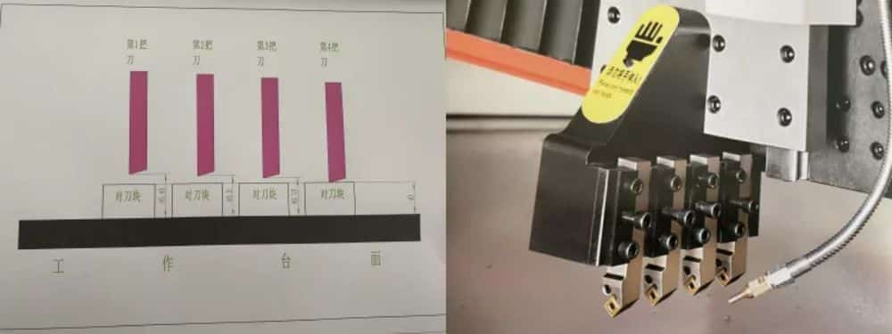
8.1. Il portautensili della macchina per scanalature verticali con portautensili singolo è costituito da uno stampo per coltelli in grado di installare 4 barre portacoltelli in lega. Lo stampo per coltelli può essere progettato per installare 4 coltelli in lega contemporaneamente, 4 coltelli in acciaio bianco contemporaneamente, oppure può essere progettato per contenere coltelli in lega e coltelli in acciaio bianco confezionati insieme.
a. Analizzato in base a 4 coltelli in lega, le lame in lega vengono installate contemporaneamente su 4 gambi di coltello. Durante l'installazione dei gambi di coltello, è presente una piastra di montaggio per coltelli sotto la punta del coltello. Il quarto coltello ha la stessa altezza della piastra del coltello e il terzo coltello è più alto del coltello. L'altezza della piastra è di 0,15 mm, il secondo coltello è più alto di 0,25 mm rispetto alla piastra del coltello e il primo coltello è più alto di 0,35 mm rispetto alla piastra del coltello. La distanza di controllo di questi coltelli può essere controllata con uno spessimetro. Allo stesso tempo, le punte di questi 4 coltelli devono essere sulla stessa linea retta, altrimenti la scanalatura standard non può essere elaborata.
b. Il metodo di installazione di un coltello in acciaio bianco è lo stesso di quello di un coltello in lega.
8.2. Il metodo di installazione del mandrino portautensili e del portautensili sull'asse Z della macchina per scanalatura verticale a doppio portautensili è lo stesso del metodo di installazione sull'asse Z del portautensili singolo. Il metodo di installazione dell'asse W è lo stesso di quello dell'asse Z, ma la direzione di installazione del mandrino portautensili è opposta.
8.3.Il metodo di installazione del mandrino portautensili della macchina per scanalatura a portale è lo stesso di quello della macchina per scanalatura verticale a singolo montante portautensili.
8.4. Dopo aver installato l'albero portautensili di una qualsiasi macchina per scanalature, il portautensili può eseguire il taglio seguendo le istruzioni del sistema e azionando il motore principale dell'asse X.
8.5.La profondità della macchina scanalatrice e l'avanzamento di ciascun asse Z sono controllati dal sistema.
8.6. Le lamiere metalliche contengono naturalmente tensioni interne, e parte di queste tensioni viene rilasciata durante il processo di scanalatura. Di conseguenza, la lamiera può piegarsi lungo la linea centrale della scanalatura. Quando vengono realizzate più scanalature con spaziatura ridotta sulla stessa lamiera, questa piegatura diventa più pronunciata, comunemente nota come "laminazione a lastra". L'entità di questa deformazione è influenzata da diversi fattori chiave: 1) l'affilatura della punta dell'utensile, 2) la concentricità dell'installazione della punta, 3) la velocità di rotazione del portautensile (sebbene il suo impatto sia minimo), 4) lo spessore della lamiera e 5) la profondità della scanalatura in lavorazione.
9.Selezione della lama e requisiti angolari per la scanalatura
9.1. In circostanze normali, per migliorare l'efficienza della lavorazione di scanalatura, i clienti utilizzano lame in lega per il taglio. Le lame in lega sono resistenti alle alte temperature e possono amplificare la velocità di taglio dell'asse X.
9.2. A causa della temprabilità, il coltello in lega non è resistente agli urti. Pertanto, la lavorazione con coltello per la formatura della lega è generalmente sconsigliata per la lavorazione di lamiere spesse.
I coltelli profilati possono essere suddivisi in coltelli ad angolo piatto e coltelli ad angolo curvato. La resistenza all'impatto del coltello ad angolo piatto è maggiore di quella del coltello ad angolo curvo. Si sconsiglia l'uso del coltello ad angolo curvo per lavorare lamiere di spessore superiore a 1 mm.
9.3. Il coltello per la formatura delle leghe ha quattro angoli a 90° su ciascun lato, per un totale di otto punte utilizzabili. Se un angolo si usura, i restanti sette possono essere ruotati e utilizzati, a condizione che non vengano danneggiati da urti. Poiché l'angolo di taglio è di 90°, anche l'angolo di scanalatura risultante è di 90°. Tuttavia, durante la piegatura, le lamiere metalliche spesso subiscono un ritorno elastico, che richiede un angolo di piegatura superiore a 90° per ottenere un angolo finale preciso. Questa sovrapiegatura causa la compressione dei due angoli della scanalatura a V, un inconveniente comune quando si utilizzano coltelli per la formatura delle leghe per la scanalatura, soprattutto nelle applicazioni di precisione.
9.4. In circostanze normali, se i clienti lavorano lamiere spesse (oltre 2 mm), consiglieranno l'utilizzo di lame in acciaio bianco. Lo svantaggio delle lame in acciaio bianco è che non sono resistenti alle alte temperature, quindi la velocità di lavorazione dell'asse X sarà notevolmente ridotta. I vantaggi delle lame in acciaio bianco: sono resistenti agli urti e possono essere tagliate e affilate con qualsiasi angolo maggiore di 30° e minore di 120°.
9.5. Per la lavorazione di piastre in ferro, impiallacciature in alluminio, piastre in alluminio-plastica, piastre in plastica e piastre in acrilico, si consiglia di utilizzare coltelli in acciaio bianco. Poiché la scanalatura di rimozione dei trucioli del coltello in acciaio bianco può essere levigata liberamente con un'angolazione che favorisce la rimozione dei trucioli.
9.6.Si consigliano modelli di coltelli in lega e coltelli in acciaio bianco.
a. Per i coltelli in lega, consigliamo Taegutec e KORLOY, due marchi importati dalla Corea del Sud.

b. Per i coltelli in acciaio bianco, solitamente consigliamo coltelli in acciaio bianco ad alto contenuto di cobalto importati dalla Svezia.

c. Per i portautensili in lega, consigliamo i portautensili Hanshiba e PSDNN2020K12.
9.7. Si consiglia che durante il processo di piegatura della lamiera scanalata, l'angolo di piegatura richiesto sia di 83° per lo stampo inferiore e di 80° per lo stampo superiore.
10. Principio meccanico della macchina scanalatrice
10.1. Principio meccanico della macchina per scanalature verticali
a. La colonna destra della scanalatrice adotta una saldatura a telaio, che può garantire la stabilità della saldatura tra il banco di lavoro, la trave della piastra di pressione e la trave anteriore. Sono presenti 4 set di viti di ancoraggio su entrambe le estremità delle colonne sinistra e destra per regolare il livello dell'attrezzatura.
b. Il banco di lavoro e il telaio del registro posteriore della macchina scanalatrice sono strutture saldate integralmente, che garantiscono parallelismo e verticalità dopo la lavorazione complessiva. La struttura principale del banco di lavoro è costituita da una scatola quadrata saldata. Ciò garantisce la stabilità della piastra di pressione e riduce l'abbassamento del banco di lavoro dovuto alla pressione esercitata dalla piastra stessa. Sono presenti 4 set di viti di regolazione del piedino sotto il banco di lavoro, che possono essere utilizzate per regolare il livello dell'attrezzatura e il ruolo di supporto svolto al centro del banco di lavoro.
c. Sotto il pannello del banco di lavoro sono presenti diverse serie di viti di regolazione, utilizzate principalmente per regolare la distanza tra il banco e ciascun punto lungo la traiettoria di lavoro della punta dell'utensile (regolabile con una precisione di più o meno 0,03 mm). Ciò garantisce che la profondità di ogni punto della lamiera lavorata rimanga invariata.
d. La trave della piastra di pressione utilizza una struttura saldata a scatola quadrata, che ne aumenta notevolmente la rigidità complessiva e garantisce la stabilità del materiale dopo la lavorazione. Questo design aiuta a prevenire flessioni direzionali o deformazioni del pezzo durante la scanalatura. Garantisce inoltre un movimento stabile dei portautensili degli assi Z e X, riducendo al minimo le ondulazioni superficiali sulla scanalatura finita. La piastra di pressione è montata sotto la trave, mantenendo un preciso allineamento parallelo con la traversa e il piano di lavoro. Le viti di regolazione fine sono integrate nella base della piastra di pressione, consentendo una regolazione precisa di entrambe le estremità per adattarle all'altezza del piano di lavoro, riducendo efficacemente i segni di indentazione sulla lamiera durante la pressatura.
e. La trave di riferimento posteriore è anch'essa progettata come una struttura a scatola quadrata per garantire parallelismo e verticalità dopo la lavorazione. Il morsetto è installato su di esso. Sono presenti anche viti di regolazione sulla sede del morsetto. Quando il morsetto blocca la lamiera, se il materiale di serraggio non è parallelo, è possibile utilizzarlo per regolarlo con precisione.
f.Il portautensili è ricavato integralmente da un pezzo di acciaio n. 45 e la sua parte a coda di rondine è tagliata integralmente mediante taglio a filo, il che garantisce la precisione di rodaggio della parte di contatto a coda di rondine.
g. Anche la piastra di serraggio del portautensili è realizzata in acciaio n. 45 e lavorata mediante taglio a filo. Questo può garantire il parallelismo tra ogni lama. I requisiti in questo caso sono molto elevati. Se la superficie di montaggio su cui sono installate le quattro barre portautensili non è sulla stessa linea orizzontale, le quattro punte degli utensili non saranno allineate e la scanalatura così lavorata non sarà qualificata.
h. Le due estremità del portautensili dell'asse X sono progettate per essere dotate di gomma elastica anticollisione, poiché la potenza del motore dell'asse X è relativamente elevata. Senza tale protezione progettuale, in caso di guasto dell'asse X, lo spazio tra l'asse X e le colonne sinistra e destra potrebbe aumentare, provocando una forte collisione e persino un morso mortale.
i. L'asse Z è inoltre progettato con un limite rigido interno, che viene utilizzato per controllare la corsa dell'asse Z e il limite inferiore dell'asse Z. Se il limite flessibile dell'asse Z non funziona, il limite rigido svolgerà un ruolo importante. protezione in modo che il coltello affilato non tagli il banco di lavoro.
10.2. Principio meccanico della macchina scanalatrice a portale
a. Il basamento della macchina scanalatrice a portale è saldato integralmente. I due lati del basamento costituiscono la tavola principale, che supporta principalmente il piano del tavolo. Sotto il piano del tavolo sono presenti diverse nervature di rinforzo saldate, in modo che la struttura del telaio del corpo scatolare garantisca la resistenza e la stabilità dell'intero basamento. Sono presenti 8 set di viti di ancoraggio progettate e saldate sul fondo del basamento per regolarne il parallelismo.
b. Il design del portale è una combinazione della piastra principale e della piastra di rinforzo, e la saldatura del telaio è utilizzata anche per garantire la resistenza e la stabilità del portale. Il motore di azionamento principale e il riduttore sono installati all'interno del portale.
c. La piastra di pressione laterale è installata sul lato operativo del basamento della macchina e viene spinta e premuta dal cilindro dell'olio (o dal cilindro), utilizzando il ritorno a molla.
d. Il piedino premistoffa anteriore è installato sull'asta lucidata dell'asse Y2. La sua traiettoria di scorrimento è controllata dalla rettilineità dell'asta lucidata. Sul banco di lavoro è presente una tacca opposta al centro dell'asta lucidata.
e. Il portautensili dell'asse Z è installato sulla traversa e la piastra portautensili è installata su due guide lineari. Ciò riduce lo spazio tra il portautensili che scorre verso l'alto e verso il basso e riduce le vibrazioni generate dal portautensili durante la lavorazione e il taglio.
e. L'albero di trasmissione è progettato con cuscinetti importati per garantire la stabilità e la durata dell'asse X durante il funzionamento.
11. Struttura elettrica e distribuzione della macchina scanalatrice
11.1.Struttura elettrica e distribuzione della macchina scanalatrice verticale
a. I principali componenti elettrici della macchina scanalatrice includono il sistema di controllo (tipo touch screen e tipo pulsante digitale), driver, trasformatore, interruttore di controllo, interruttore di prossimità, trasformatore, scheda IO, resistore, cavo super flessibile, relè, interruttore di attesa.
b. Il sistema viene installato sul lato operativo della macchina scanalatrice. Sono disponibili due metodi di installazione: con braccio mobile sospeso e con braccio girevole. L'altezza operativa può essere progettata in base alle esigenze del cliente.
c. Il quadro elettrico e il trasformatore sono tutti installati nel telaio della colonna destra della scanalatrice. Ciò garantisce la sicurezza dell'attrezzatura durante il trasporto, consente di risparmiare spazio per il montaggio e ha anche un effetto estetico.
d. Gli interruttori di prossimità sono progettati sugli assi X, Y, Z e W per controllare l'allineamento dell'origine di ciascun asse.
Un dispositivo di illuminazione è installato sotto la trave anteriore della macchina scanalatrice, in modo che l'operatore possa vedere chiaramente l'ambiente della superficie di lavoro e osservare l'usura della lama.
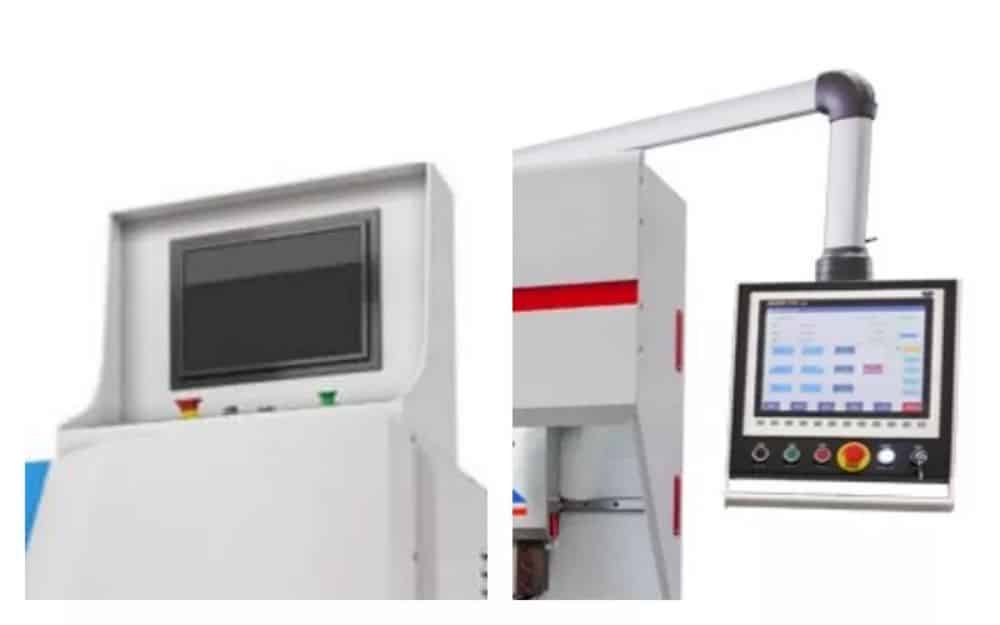
11.2.Struttura elettrica e distribuzione della macchina scanalatrice a portale
a. I principali componenti elettrici della macchina scanalatrice a portale includono il sistema di controllo, il driver, il trasformatore, l'interruttore di controllo, l'interruttore di prossimità, il convertitore di frequenza, la scheda IO, il resistore, il relè, l'interruttore automatico, il cavo super flessibile, ecc.
b. Il sistema è installato sull'estremità superiore della trave dell'asse X. Ciò facilita la flessibilità operativa dell'operatore.
c. I quadri elettrici e i trasformatori sono tutti installati all'interno della trave dell'asse X. Questa progettazione accorcerà e ridurrà la distanza di collegamento tra il sistema e ciascun apparecchio elettrico.
d. Gli interruttori di prossimità sono progettati sugli assi X, Y1, Y2 e Z per controllare l'allineamento dell'origine di ciascun asse.
12. Principi idraulici e pneumatici della macchina scanalatrice
12.1.La parte idraulica della macchina scanalatrice verticale è composta da: una stazione idraulica, un manometro, diversi cilindri dell'olio e tubi flessibili ad alta pressione.
a. Dopo l'avvio del motore, l'olio idraulico verrà trasportato all'accumulatore tramite la pompa dell'olio. Quando la pressione dell'accumulatore raggiunge il valore di altezza impostato, il motore si arresterà automaticamente (ciò consentirà di risparmiare energia e di ridurre efficacemente la temperatura dell'olio).
b. Quando si preme il pulsante per premere la piastra di pressione o per bloccare la pinza, l'elettrovalvola sul gruppo valvole viene eccitata per aprire il nucleo della valvola. L'olio idraulico nell'accumulatore entra nel cilindro attraverso l'elettrovalvola e poi passa attraverso lo stelo del cilindro dell'olio, spingendo la piastra di pressione (piastra di serraggio) per premere e bloccare il pezzo. Quando questi due pulsanti vengono premuti nuovamente, la porta di scarico dell'accumulatore viene chiusa, la bobina dell'elettrovalvola torna nella sua posizione originale e la piastra di pressione scarica l'olio idraulico nel cilindro nel serbatoio tramite la forza elastica della molla.
c. Dopo più di N cicli di azionamento, l'olio idraulico nell'accumulatore diminuirà progressivamente. Quando la sua pressione interna sarà inferiore al valore di bassa pressione da noi progettato, il motore si avvierà immediatamente e farà passare nuovamente l'olio idraulico attraverso la pompa dell'olio. Il lavoro viene trasferito all'accumulatore.
12.2.Il principio idraulico della macchina scanalatrice a portale è lo stesso della macchina scanalatrice verticale.
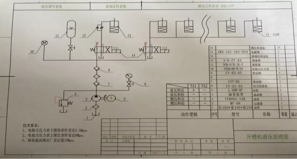
Schema idraulico
12.3.La parte pneumatica della macchina per scanalature verticali è composta da un compressore d'aria, un elemento di elaborazione della fonte d'aria, diverse elettrovalvole, diversi cilindri e tubi dell'aria.
a. Poiché il serbatoio dell'aria del compressore è stato azionato dal motore, al suo interno è stata immagazzinata una determinata fonte d'aria. Quando si preme il pulsante di pressatura o serraggio, la fonte d'aria nel serbatoio passa attraverso l'elettrovalvola. Quando il pezzo entra nel cilindro, il pistone del cilindro spinge la piastra di pressione per trattenere il foglio. Quando i due pulsanti vengono premuti nuovamente, la direzione di azione dell'elettrovalvola cambia e la fonte d'aria entra nell'altra cavità del cilindro. Questo apre la piastra di pressione.
12.4.Il principio pneumatico della macchina per scanalatura a portale è lo stesso della macchina per scanalatura verticale, ovvero la corsa di ritorno del cilindro della piastra di pressione utilizza una corsa di ritorno a molla.
13.Tabella di configurazione di Macchina per scanalature a V per lamiere
| NO. | Nome | Tipo | Quantità |
| 1 | Sistema CNC | Tecnologia di controllo Edraw di Taiwan | 1 set |
| 2 | Motore del mandrino | 5,5 kW | 1 |
| 3 | Servomotore | 2 kW | 1 |
| 4 | Servomotore | 1 kW | 2 |
| 5 | Guide lineari | 35mm、25mm | 2 gruppi ciascuno |
| 6 | Vite a sfere | θ32mm | 2 gruppi ciascuno |
| 7 | Cavo per catena portacavi | 2.0 quadrato, 1.5 quadrato, 1.0 quadrato | Cavo flessibile ad alte prestazioni IGUS tedesco |
| 8 | Componenti elettrici | FranciaSchneidevSchneider | |
| 9 | cilindro | Cilindro standard θ80 | Airtac (Taiwan) Co., Ltd. |
| 10 | cilindro | Cilindro standard θ80 | Airtac (Taiwan) Co., Ltd. |
| 11 | Cilindro dell'olio | Cilindro standard θ30 | Shandong Jining Taifeng idraulico |
| 12 | Cuscinetti a sfere a contatto obliquo | 7025AWP5 908 | Giappone NSK |
| 13 | Cuscinetti a sfere a contatto obliquo | 7025AWP5 802 | Giappone NSK |
| 14 | cuscinetto piano | 51305 907 | Giappone NSK |
| 15 | stazione idraulica | 6,3 litri | Shandong Jining Taifeng idraulico |
| 16 | Accoppiamento | Θ22 | |
| 17 | Lama in lega | KORLOY、TaegUTec | Prodotto in Corea (facoltativo) |
| 18 | Portautensili | PSDNN2020K12 | Leone tiranno della siccità |
| 19 | Lama in acciaio bianco | ASSAB 17 | PRODOTTO IN SVEZIA |
14. Parametri tecnici della macchina scanalatrice
| Tipo | HSV-4000×1250 | |
| Gamma di elaborazione | 4000mmX1250mmx0,5-6mm | Parallelismo del foglio <2mm |
| Configurazione del sistema | metodo di controllo | Controllo CNC a 4 assi (X, Y, Z, W) |
| monitorare | Schermo touch Edraw da 15 pollici (opzionale) | |
| capacità di stoccaggio | 99 gruppi, 999 modi (può essere ripetuto 99 volte) | |
| metodo di trasferimento | Motore principale, vite a sfere, guida lineare, cremagliera | |
| dispositivo di serraggio | Pneumatico, idraulico | Opzionale |
| Precisione | Precisione di posizionamento dell'asse X del montante utensile principale | ±0,05 mm |
| Precisione di posizionamento dell'asse Y del registro posteriore | ±0,03 mm | |
| Precisione di posizionamento dell'asse Z del portautensili | ±0,02 mm | |
| Precisione di posizionamento dell'asse W del portautensili | ±0,02 mm | |
| Velocità di elaborazione | Asse X del montante utensile principale | 0-90 m/min |
| Asse Y del registro posteriore | 0-90 m/min | |
| Portautensili asse Z, asse W | 0-20 m/min | |
| Precisione strutturale del letto del tornio | Parallelismo del banco da lavoro | ±0,06 mm |
| Parallelismo della guida della traversa del portautensili | ±0,03 mm | |
| Parallelismo della guida di scartamento posteriore | ±0,03 mm | |
| Diametro del cilindro della pressa | cilindro | Θ80mmx30mm |
| Cilindro dell'olio | Θ30mmx32mm | |
| Margine minimo per l'inserimento | 10 millimetri | |
| Dimensioni | 6000m 5500mmX2150mmX1900mm 5880m*2150mm*1500mm | |
| Peso della macchina | Circa 10,5 tonnellate (macchina per scanalatura verticale) Circa 7,8 tonnellate (macchina per scanalatura a portale) | |
15. Specifiche e modelli delle macchine scanalatrici
15.1.Specifiche e modelli delle macchine scanalatrici verticali
Modello: HSV Specifiche: HSV-2500X12500-3200, HSV-3200X1250-3200 HSV-4000X1250-3200, HSV-5000X1250-3200, HSV-6000X1250-3200.
Nota: vari tipi di macchine per scanalature di porte di sicurezza e varie macchine per scanalature non standard possono essere personalizzate in base alle esigenze del cliente.
15.2.Specifiche e modelli della macchina scanalatrice a portale
Modello: HSL Specifiche: HSL-2500X1250-1500, HSL-3200X1250-1500, HSL-4000X1250-1500, HSL-5000X1250-1500, HSL-6000X1250-1500
16. Standard e parametri di ispezione in fabbrica delle macchine scanalatrici
16.1. Standard e parametri di ispezione in fabbrica delle macchine per scanalature verticali
a. Verificare se ci sono evidenti differenze di colore nella vernice dell'attrezzatura, se la superficie della vernice è liscia e se ci sono scrostature.
b. Controllare il giunto di saldatura per verificare la presenza di perdite, pori, scorie di saldatura e schizzi.
c. Verificare che le viti di ciascun componente siano allentate. Verificare che i dispositivi di visualizzazione, i selettori e i pulsanti siano disposti in modo ordinato, bello e flessibile.
d. Controllare ogni parte annerita per verificare se c'è ruggine sulle parti non annerite.
e. Utilizzare un comparatore a quadrante per fissare il portautensili nella posizione in cui è installato e spostare il portautensili in modalità manuale per verificare. La tolleranza di distanza tra il portautensili e il pannello del banco di lavoro è di ±0,03 mm.
f. Avviare l'attrezzatura, ispezionare visivamente e percepire il fenomeno delle vibrazioni quando il portautensili è in funzione per determinare la correttezza dell'installazione di ingranaggi, cremagliere e guide lineari.
g. Avviare l'attrezzatura e controllare ogni cilindro dell'olio, cilindro, giunto del tubo dell'olio e giunto del tubo dell'aria per verificare la presenza di perdite di olio, perdite d'aria, ecc.
h. Verificare che il cilindro dell'olio e la pressione dell'aria raggiungano il valore di pressione richiesto quando l'attrezzatura è in funzione. La pressione dell'olio è di 11 MPa e la pressione dell'aria è di 0,6 MPa.
i. Verificare la flessibilità degli assi X, Y, Z e W (solitamente basata sulla spinta e sulla rotazione della mano).
j. Controllare che tutte le parti mobili siano lubrificate.
k. Utilizzare una piastra di ferro 4000x1250x1,0 per avviare l'elaborazione delle dimensioni di input. La spaziatura delle scanalature di lavorazione è 10 mm, 50 mm, 100 mm, 300 mm, 500 mm, 1100 mm e la profondità di lavorazione è 0,5 mm. Al termine della lavorazione, controllare la distanza tra ciascuna scanalatura. La tolleranza consentita entro 500 mm è ±0,1 m e la tolleranza consentita entro 1100 mm è ±0,15 mm.
l. Dopo aver lavorato l'intera tavola, osservare se la profondità di ogni scanalatura è uniforme e se sono presenti evidenti linee di vibrazione e bave. Quindi verificare se sono presenti evidenti rientranze sul retro.
f. Quindi capovolgere la piastra per eseguire le scanalature inverse. Le dimensioni sono 20 mm, 200 mm, 600 mm e 1000 mm. La profondità di lavorazione è anch'essa di 0,5 mm. Al termine della lavorazione, verificare che l'errore tra le scanalature anteriore e posteriore sia compreso entro ±0,2 mm.
g. Dopo aver completato l'ispezione finale, verificare se gli assi X, Y, Z e W riescono a tornare con precisione alla posizione di origine.
h. Premere verso il basso la piastra di pressione e utilizzare uno spessimetro per verificare se i morsetti corrispondono alle aperture inferiori delle piastre di pressione e alle loro aperture inferiori. In caso contrario, è necessario regolare le viti di regolazione fine superiori per farle corrispondere.
16.2. Standard e parametri di ispezione della macchina scanalatrice a portale.
Le ispezioni della scanalatrice a portale sono le stesse della scanalatrice verticale, ad eccezione dell'ispezione aggiuntiva. La tolleranza tra la punta dell'utensile e qualsiasi punto del banco di lavoro non può essere superiore a 0,03 mm.
17. Guasti comuni e metodi di risoluzione dei problemi delle macchine scanalatrici
17.1. Guasti meccanici comuni e metodi di risoluzione dei problemi delle macchine per scanalatura verticale e delle macchine per scanalatura a portale
a. Quando queste due macchine scanalatrici sono in funzione ininterrottamente, la piastra di pressione e i morsetti vengono costantemente serrati. Quando vengono aperti, le viti sui giunti del cilindro dell'olio (cilindro) si allentano facilmente (utilizzare una chiave adatta per serrare nuovamente).
b. Se l'operatore non effettua rifornimenti frequenti e l'ambiente di lavoro dell'attrezzatura è relativamente scadente, le guide lineari, le viti a sfere, i cuscinetti, gli alberi di trasmissione, gli ingranaggi e le cremagliere saranno privi di olio lubrificante o saranno intaccati dalla polvere e danneggiati e sollecitati.
c. Sotto il tavolo della macchina per scanalature verticali sono presenti numerose viti di regolazione. A causa della continua compressione della piastra di pressione nella fase iniziale, si creerà un certo gioco. Entro un mese dal primo utilizzo dell'attrezzatura, è necessario utilizzare un comparatore per verificarne la posizione. Se si riscontrano variazioni locali, regolare le viti di regolazione sottostanti per una messa a punto precisa del tavolo. Generalmente, dopo una o due regolazioni, non si noteranno variazioni.
17.2. Guasti comuni dei circuiti e metodi di risoluzione dei problemi per macchine per scanalatura verticale e macchine per scanalatura a portale
a.PLC007 allarme dispositivo di controllo esterno!
b.Allarme limite software asse (X, Y, Z, W)
c.allarme di arresto di emergenza
17.3.Allarme di arresto di emergenza
Premere l'interruttore di arresto di emergenza in stato di arresto. Dopo aver verificato la situazione, rilasciare il pulsante di arresto di emergenza e premere RESET per ripristinare.
17.4.Se la posizione corrispondente dell'asse Z è troppo grande quando.
17.5. L'errore di inseguimento degli assi (X, Y, Z, W) è troppo grande. Controllare la rigidità o i parametri del servo.
a. Controllare il parametro seguendo l'intervallo di progettazione del valore di errore e aumentare il seguente intervallo di valori.
b. Verificare se il portautensili o il motore sono bloccati.
c. Verificare che il cablaggio sia scollegato.
d. Modificare i parametri o disattivare il rilevamento del valore di errore.
18. Portautensili singoli e doppi nella scanalatura
18.1.Nelle prime fasi di sviluppo della macchina CNC per scanalature a V, l'albero principale (asse X) era inizialmente azionato da una vite a sfere a passo largo. Sebbene avessimo aggiunto un supporto protettivo per l'utensile sopra la vite, la lunghezza e il peso della vite limitavano la velocità di movimento del portautensile durante il taglio e il ritorno. L'aumento della velocità avrebbe causato vibrazioni e possibili deformazioni, riducendo l'efficienza complessiva della lavorazione. Per risolvere questo problema, abbiamo riprogettato il sistema per consentire al portautensile di eseguire il taglio anche durante la corsa di ritorno. Ciò ha portato all'introduzione di un doppio portautensile, migliorando significativamente le prestazioni e la produttività.
18.2. Dopo i miglioramenti apportati alla progettazione e al processo produttivo, l'azionamento dell'albero principale (asse x) della macchina per scanalatura è stato sostituito dall'originale azionamento a vite a sfere con un azionamento a cremagliera e pignone. Poiché la cremagliera e il pignone risolvono i difetti causati dalla trasmissione a vite a sfere, la velocità di rotazione del portautensile aumenta notevolmente, sia in fase di lavorazione, taglio o ritorno. In questo modo, la macchina per scanalatura con doppio portautensile perde i suoi vantaggi originali.
18.3. Grazie all'aumento della velocità della macchina per scanalature con portautensile singolo, l'intera velocità di ritorno di 4000 mm richiede solo 2 secondi, e dispone di un solo portautensile. L'installazione e la messa a punto dell'albero portautensili sul portautensile saranno molto più semplici rispetto a quelle del portautensile doppio, in particolare con 4 utensili. La concentricità del coltello è facile da regolare.
18.4. Poiché la macchina scanalatrice con doppio portautensili è progettata con due portautensili e la larghezza di un set di portautensili è di 300 mm, quando il doppio portautensili è in lavorazione, sia in lavorazione che in ritorno, è necessario immettere una corsa aggiuntiva di 300 mm, in modo che il doppio portautensili percorra 600 mm in più rispetto a un singolo portautensili per un viaggio di andata e ritorno, il che comporta una notevole perdita di tempo di lavoro.
18.5. Poiché i due set di portautensili doppi contengono 8 coltelli (4 per gruppo), l'attrezzatura ha requisiti molto elevati in termini di concentricità degli 8 coltelli durante la messa a punto, poiché le lame devono essere costantemente usurate. Inoltre, interrompere l'attività dell'attrezzatura per la sostituzione delle lame comporta una perdita di tempo.
18.6. Poiché la produzione, l'assemblaggio e la messa a punto di una macchina per scanalatura verticale a doppio utensile sono più complesse rispetto a una macchina per scanalatura verticale a singolo utensile, i costi di produzione aumenteranno, quindi il prezzo di vendita sarà generalmente più alto di quello di una macchina per scanalatura verticale a singolo utensile. Il prezzo della macchina per scanalatura è compreso tra 30.000 e 40.000 yuan.
18.7. Sulla base dei fattori sopra indicati, in genere consigliamo ai clienti di acquistare una macchina per scanalatura con un solo portautensile, perché abbiamo osservato che alcuni clienti acquistano una macchina per scanalatura con due portautensili, ma in realtà utilizzano un solo portautensile per la lavorazione.
19. Confronto delle prestazioni tra macchina per scanalatura verticale e macchina per scanalatura a portale
19.1.Copertura
Le dimensioni di queste due scanalatrici sono sostanzialmente le stesse, ma l'altezza della scanalatrice verticale è maggiore rispetto a quella della scanalatrice a portale, quindi l'effetto visivo è leggermente peggiore. Generalmente, lo spazio in magazzino è limitato, quindi i clienti opteranno per la scanalatrice a portale.
19.2. Comodità di carico e scarico dei pannelli
a. Poiché l'estremità anteriore della scanalatrice verticale è aperta, dopo la lavorazione del pezzo, il registro posteriore invierà la lamiera all'estremità anteriore dell'attrezzatura, rendendo molto comodo per l'operatore salire e scendere dalla lamiera. Ci sono anche verticali. Il banco di lavoro della scanalatrice è relativamente stretto e il supporto anteriore è progettato con molte sfere universali, in modo che il movimento della lamiera sulla piattaforma sia molto flessibile, il che è anche molto comodo e pratico per la lavorazione di lamiere più spesse.
b. La piattaforma di lavoro della scanalatrice a portale è relativamente ampia. Se si lavora un'intera piastra o una lamiera relativamente grande, sarà più difficile caricare e scaricare il materiale. Inoltre, sulla parte anteriore della lamiera in acciaio inossidabile è generalmente presente una pellicola protettiva, per cui quando la lamiera viene spostata, si forma una barriera di attrito tra la pellicola protettiva e la superficie del banco di lavoro. Se la lamiera viene lavorata, spostarla sarà più dispendioso in termini di tempo e fatica.
19.3.Confronto dell'intervallo di elaborazione
La scanalatrice verticale può lavorare lamiere con uno spessore da 0,5 a 6 mm. La scanalatrice a portale può lavorare lamiere con uno spessore da 0,5 a 4 mm. La scanalatrice verticale può lavorare lamiere fino a 4000 mm di lunghezza x 4000 mm di larghezza, mentre la scanalatrice a portale può lavorare lamiere fino a 4000 mm di lunghezza x 1250 mm di larghezza.
19.4.Confronto della velocità di elaborazione
Poiché il portautensili della macchina per scanalatura verticale è relativamente leggero, la sua velocità di esecuzione sarà corrispondentemente più veloce e presenta anche un design a doppio portautensili, che consentirà di risparmiare una certa quantità di ore di lavoro durante l'elaborazione delle scanalature di densità dell'intera scheda, mentre la macchina per scanalatura a portale elabora la trave che deve essere spostata, quindi la velocità di elaborazione sarà inferiore a quella della macchina per scanalatura verticale.
19.5.Confronto del risparmio energetico
Poiché il portautensili della macchina per scanalatura verticale pesa solo circa 300 kg, mentre la trave della macchina per scanalatura a portale pesa circa 900 kg, durante la lavorazione il consumo energetico del motore principale sarà inferiore per la macchina per scanalatura verticale rispetto alla macchina per scanalatura a portale.
19.6.Confronto tra costi di produzione e prezzi di vendita
Poiché la macchina per scanalatura verticale ha più parti, peso, tecnologia di lavorazione, tecnologia di assemblaggio, ecc. rispetto alla macchina per scanalatura a portale ed è più complicata, il prezzo di vendita della macchina per scanalatura verticale sarà più alto di quello della macchina per scanalatura a portale.
19.7.Confronto tra pezzi lavorati e scanalatura anteriore e posteriore
a. Le scanalatrici verticali e le scanalatrici a portale differiscono principalmente nel funzionamento. Nelle scanalatrici verticali, la trave portautensili rimane fissa mentre la lamiera si muove durante la lavorazione. Al contrario, le scanalatrici a portale hanno una trave portautensili mobile e la lamiera rimane fissa. La piastra di pressione della macchina verticale rimane direttamente sulla linea di scanalatura, garantendo stabilità, mentre i pressori laterali e anteriori del modello a portale fissano solo un bordo della lamiera. Pertanto, lavorazioni come lamiere pretagliate da macchine laser, materiali di forma irregolare, scanalature inclinate o scanalature con profili speciali possono essere gestite efficacemente solo dalle scanalatrici verticali.
b. Poiché il portautensili della macchina per scanalatura verticale è più leggero di quello della macchina per scanalatura a portale, anche la loro inerzia di lavoro è diversa, quindi alcune scanalature a punto fisso possono essere completate solo dalla macchina per scanalatura verticale.
c. Poiché la scanalatrice verticale utilizza un registro posteriore che tira o spinge il materiale in lamiera lavorato per spostarlo, mentre la lamiera della scanalatrice a portale non si muove, quando si eseguono le scanalature anteriori e posteriori del materiale in lamiera, il portale è aperto. La scanalatrice a portale presenta alcuni vantaggi.
e. Sulla base dei fattori sopra menzionati, consigliamo comunque prodotti adatti ai clienti in base alle loro esigenze.
20. Raccomandazioni per la selezione delle macchine scanalatrici da parte del cliente
In genere consigliamo ai clienti se acquistare una macchina per scanalatura verticale o una macchina per scanalatura a portale in base ai seguenti punti.
20.1. È necessario distinguere la tipologia di cliente. Se viene utilizzata in un magazzino, poiché lo spazio del magazzino è relativamente limitato, la quantità di scanalature a densità elevata e alcune lamiere sottili vengono lavorate, tali gruppi di clienti acquisteranno macchine per scanalatura a portale. Poiché lo stabilimento è relativamente aperto e alcuni dei prodotti vengono lavorati in proprio, tali clienti sceglieranno di acquistare una macchina per scanalatura verticale dopo aver considerato molti fattori.
20.2. Dipende dall'attrezzatura esistente del cliente. Se il cliente dispone già di una scanalatrice a portale, forniremo un esempio per illustrare i vantaggi della scanalatrice verticale. Se il cliente dispone già di una scanalatrice verticale, spiegheremo la superiorità della scanalatrice a portale.
20.3. Quando consigliamo, che si tratti di un modello verticale o a portale, cerchiamo di consigliare le macchine standard HSV-4000-1250 e HSL-4000-1250. Poiché questi due modelli sono macchine standard, il nostro ciclo di produzione è rapido e i costi saranno contenuti. Attualmente, questi due modelli sono i modelli più venduti sul mercato.
21. Sollevamento e trasporto della macchina scanalatrice
21.1. I fori di sollevamento sono riservati dietro la trave anteriore della scanalatrice verticale e ad entrambe le estremità dietro la trave portautensili, e il peso della scanalatrice da noi progettata è distribuito nella parte inferiore e centrale dell'attrezzatura, quindi il sollevamento è molto semplice e sicuro in termini di trasporto e movimentazione. A differenza delle attuali scanalatrici verticali prodotte nel Guangdong, il baricentro è completamente in alto, quindi ciò comporterà svantaggi durante il sollevamento e la movimentazione.
21.2. I golfari di sollevamento sono saldati a entrambe le estremità della macchina per scanalatura a portale e il suo basamento è di tipo a piattaforma. Il baricentro è posizionato nella parte inferiore dell'attrezzatura, rendendolo comodo e sicuro da sollevare e trasportare.
22. Cura e manutenzione della macchina per scanalature
22.1. Prima di utilizzare la scanalatrice, il banco di lavoro e le altre parti devono essere puliti da detriti. È necessario aggiungere olio lubrificante alle principali parti mobili. Verificare che le viti sulla piastra di pressione e sul portautensili siano allentate.
22.2.In modalità manuale, verificare se gli assi X, Y, Y2, Z e W funzionano normalmente.
22.3. Premere il pulsante di reset a un tasto e osservare se gli assi tornano normalmente all'origine. Dopo la conferma, iniziare a inserire i valori dimensionali e inserire il foglio per l'elaborazione.
22.4. Una volta completata l'elaborazione, premere il pulsante di reset a un tasto per riportare ciascun asse alla posizione di origine.
22.5.Se l'attrezzatura non verrà utilizzata per un lungo periodo, utilizzare carta oleata protettiva per attaccare le posizioni di ciascuna guida e vite a sfere oppure, se possibile, utilizzare una pellicola protettiva per coprire l'attrezzatura.
23. Configurazione della macchina per scanalature: ambiente, olio e pompa dell'aria
23.1. Poiché la macchina per scanalatura è un processo di taglio con portautensili in funzione, in particolare la macchina per scanalatura a portale, poiché il movimento della trave è vibrante, il terreno deve essere piano e avere una fondazione in calcestruzzo. Tuttavia, quando progettiamo la macchina per scanalatura, consideriamo attentamente questi fattori, abbiamo progettato il baricentro della macchina per scanalatura più basso, in modo che l'attrezzatura stessa abbia un certo grado di stabilità, quindi generalmente non è necessario installare viti di bloccaggio.
23.2. Ad eccezione del lato in cui l'operatore effettua le operazioni di carico e scarico (qui deve esserci spazio sufficiente), la distanza tra gli altri tre lati e il muro o altre attrezzature è di un metro. L'ambiente di lavoro non deve essere troppo polveroso e il terreno non deve accumulare acqua per lungo tempo.
23.3. Il numero di olio idraulico è lo stesso di quello delle cesoie e delle piegatrici. Si tratta dell'olio idraulico antiusura n. 46.
23.4. La potenza del modello della pompa dell'aria è la seguente:

| W-0.9/8 W0.9/12.5 | ||||||||||
| Energia | Velocità | Capacità | Pressione massima | Serbatoio d'aria | peso | Dimensioni del pacchetto | ||||
| KW | HP | giri al minuto | litri/min | CFM | Sbarra | L | Gai | kg | cm | |
| 7.5 | 10 | 850 | 900 | 31.8 | 8 | 115 | 160 | 60.8 | 150 | 150*52*100 |
| 7.5 | 10 | 950 | 900 | 31.8 | 12.5 | 178 | 160 | 41.6 | 150 | 150*52*100 |
| V-06/8 | ||||||||||
| Energia | Velocità | Capacità | Pressione massima | Serbatoio d'aria | peso | Dimensioni del pacchetto | ||||
| KW | HP | giri al minuto | litri/min | CFM | Sbarra | L | Gai | kg | cm | |
| 4 | 5.5 | 850 | 600 | 21.2 | 8 | 115 | 90 | 23.4 | 110 | 120*46*87 |
24. Tipi di scanalature vs risultati di piegatura
25. Concentrarsi sulle differenze e sui principi di Macchine per scanalature idrauliche e macchine pneumatiche per scanalature
Scegliamo se acquistare una macchina idraulica o pneumatica, proprio come acquistiamo un'auto, se un'auto a benzina o un'auto a energia rinnovabile. Entrambe le macchine per scanalatura possono effettivamente ottenere l'effetto di scanalatura, quindi come possiamo scegliere meglio? Per trovare una macchina per scanalatura adatta, la analizzeremo e la confronteremo in dettaglio in base ai seguenti punti. Quando abbiamo progettato e prodotto per la prima volta la scanalatura, l'abbiamo progettata per essere idraulica, perché a quel tempo i componenti pneumatici non erano ancora pienamente diffusi. Tuttavia, dopo molti anni di utilizzo, alcuni difetti della macchina per scanalatura idraulica sono diventati evidenti.
25.1.Confronto tra fenomeni di perdite d'olio e di perdite d'aria
a. Le macchine scanalatrici idrauliche sono costituite da componenti come centrali idrauliche, cilindri, tubi ad alta pressione e giunti. Queste parti sono soggette a problemi come perdite d'olio e guasti ai cilindri. Ad esempio, una macchina standard da 4 metri presenta fino a 64 potenziali punti di perdita, inclusi 12 cilindri a piastra di pressione, 7 cilindri di serraggio e sistemi ausiliari. Nelle macchine verticali, qualsiasi perdita dai cilindri a piastra di pressione montati sulla trave può contaminare direttamente la lamiera sottostante, il che è inaccettabile per gli utenti finali. Inoltre, le perdite d'olio causano cali di pressione, costringendo la pompa dell'olio a lavorare eccessivamente. L'usura di valvole, accumulatori, motori o pompe aumenta anche i rischi di manutenzione e l'instabilità operativa.
b. Se si sceglie una scanalatrice pneumatica, non ci si deve preoccupare di questi fenomeni. Anche in caso di perdite d'aria nel cilindro, nel tubo dell'aria o nel giunto del tubo dell'aria, non si verificheranno effetti negativi. Poiché la pompa dell'aria immagazzina una grande quantità d'aria, ha un impatto minimo sul compressore.
25.2.Confronto dei principi di funzionamento
a. Il diametro del cilindro della scanalatrice idraulica è di 25 mm, mentre il diametro del cilindro della scanalatrice pneumatica è di 80 mm. La forza di leva della piastra di pressione della scanalatrice idraulica è 1:1, ovvero la forza esercitata dalla piastra di pressione dal cilindro idraulico è uguale. La forza di leva della piastra di pressione è 3:1, il che significa che la spinta del cilindro genererà una pressione 3 volte superiore alla piastra di pressione, secondo questo principio. Sulla base dell'analisi di cui sopra, la logica secondo cui la compressione pneumatica non è ermetica non è valida.
b. Costi di produzione, perché se si tratta di un progetto idraulico, verranno aggiunti molti componenti, come una stazione idraulica, un accumulatore, un motore, una pompa dell'olio, un cilindro dell'olio e un tubo dell'olio, che aumenteranno il costo dei materiali e della manodopera, e dovranno essere equipaggiati. È presente un compressore d'aria. Se si utilizza una scanalatrice pneumatica, i componenti di cui sopra non saranno necessari, ma solo un compressore d'aria, diversi cilindri e tubi dell'aria.
c. Costo di utilizzo. Se si tratta di una scanalatrice idraulica, è necessario aggiungere olio idraulico n. 46, pulire il serbatoio e sostituire regolarmente l'olio idraulico. Le scanalatrici pneumatiche non richiedono questa spesa.
d. I costi di manutenzione delle scanalatrici idrauliche sono spesso elevati perché componenti chiave come la stazione idraulica, il serbatoio dell'olio, i cilindri e i giunti per tubi sono realizzati su misura dal produttore. In caso di problemi, i pezzi di ricambio non possono essere reperiti sul mercato libero e devono essere acquistati direttamente dal fornitore originale, spesso a prezzi notevolmente gonfiati. Al contrario, le scanalatrici pneumatiche utilizzano componenti standard come cilindri, elettrovalvole e tubi dell'aria, ampiamente disponibili e convenienti. Inoltre, se un produttore interrompe la produzione di uno specifico modello idraulico, i pezzi di ricambio potrebbero non essere più disponibili, con conseguenti riparazioni costose e dispendiose in termini di tempo che possono bloccare completamente la produzione.
Sulla base dell'analisi di cui sopra, riteniamo che le scanalatrici pneumatiche rappresentino anche la direzione di sviluppo futura. La nostra azienda produce due modelli di scanalatrici idrauliche e pneumatiche, e abbiamo progettato sia macchine idrauliche che pneumatiche, sia verticali che verticali. Che si tratti di una scanalatrice o di una scanalatrice a portale, entrambe utilizzano lo stesso basamento.


