


La modalità manuale DELEM DA-66S offre agli utenti la flessibilità necessaria per eseguire operazioni di piegatura precise indipendentemente dalle impostazioni automatiche. Con la modalità manuale, gli operatori possono ottenere il pieno controllo del processo di piegatura, personalizzando i parametri per ogni lavoro. Questa modalità è ideale per applicazioni che richiedono regolazioni specifiche che le impostazioni automatiche potrebbero non supportare.
In questo articolo approfondiremo le funzionalità principali della modalità manuale DELEM DA-66S, fornendoti una guida completa per migliorare le prestazioni e la produttività della tua macchina.
Panoramica della modalità manuale
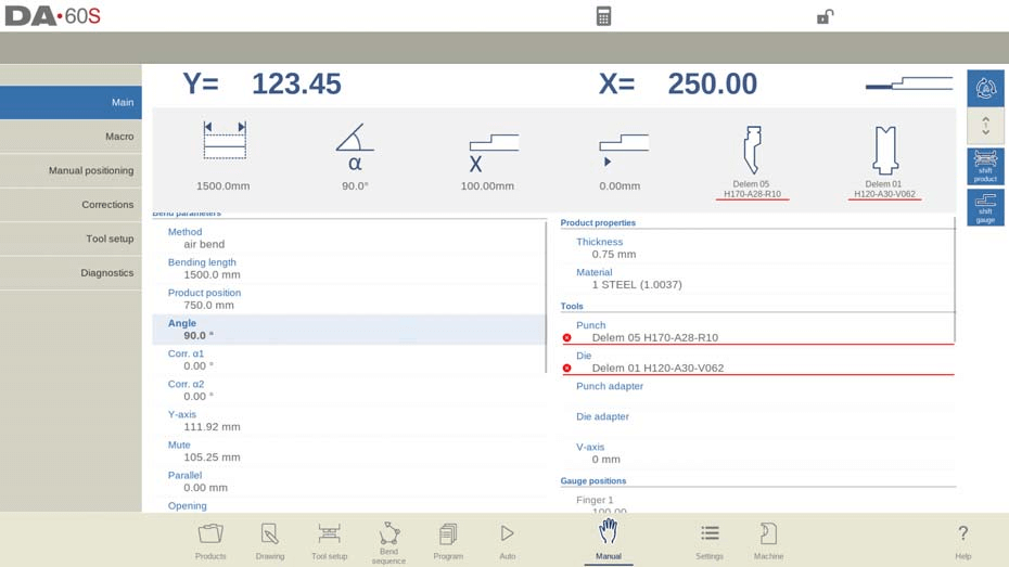
La modalità manuale DELEM DA-66S consente agli utenti di controllare manualmente il pressa piegatrice, indipendentemente dai programmi predefiniti. Passando alla modalità manuale, è possibile visualizzare sullo schermo le posizioni in tempo reale degli assi chiave, come l'asse Y e l'asse X principale. Questi indicatori garantiscono che i marcatori di riferimento siano correttamente allineati con i valori programmati per operazioni di piegatura precise.
In modalità manuale si programmano i parametri per una singola piegatura. Questa modalità è utile per prove, calibrazioni e per piegature singole.
La modalità manuale è indipendente dalla modalità automatica e può essere programmata indipendentemente dai programmi in memoria.
Nella parte superiore della schermata della modalità Manuale è possibile trovare la posizione corrente dell'asse Y e dell'asse X principale. Tutti gli altri assi e le funzioni sono elencati uno per uno nelle due colonne sottostanti. Quando i valori degli assi Y e X sono evidenziati, significa che i marcatori di riferimento di questi assi sono stati trovati e che sono posizionati correttamente rispetto ai valori programmati.
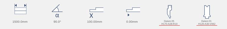
Sopra gli assi e le funzioni, grandi icone (tile) con i valori correlati mostrano quelli più utilizzati. Questi tile possono essere selezionati e i valori possono essere modificati direttamente.
Di seguito è riportato un elenco dei parametri disponibili in modalità Manuale.
Parametri di piegatura
Metodo
Selezionare il metodo di piegatura desiderato. Il controllo supporta i seguenti metodi standard:
• Curvatura ad aria
• Toccare il fondo
• Orlatura
• Orlatura e cucitura del fondo

I metodi di piegatura sono stati spiegati più dettagliatamente nella modalità Programma.
Metodo di deviazione
Dinamico: la bombatura verrà controllata automaticamente in tempo reale durante la piegatura, applicando le opportune correzioni quando necessario.
Non dinamico: la bombatura si comporterà come una bombatura idraulica standard; non ci saranno correzioni in tempo reale.
Lunghezza di piegatura
Programmare la lunghezza di piegatura del foglio.
Posizione del prodotto
Valore assoluto della posizione del prodotto nella direzione Z. Il lato sinistro della macchina è la posizione di riferimento zero.
Angolo
Angolo di piegatura.
Corr.α 1, Corr.α 2
Correzione dell'angolo di piegatura.
La correzione dell'angolo deve essere inserita come indicato nei seguenti esempi:
Valore programmato di 90 gradi. Valore misurato di 92 gradi. Quindi è necessario programmare Corr.α con -2.
Valore programmato di 90 gradi. Valore misurato di 88 gradi. Quindi è necessario programmare Corr.α con +2.
Apertura dell'orlo
La piegatura dell'orlo può essere realizzata con una certa distanza di apertura tra le due flange. Il valore di apertura dell'orlo verrà utilizzato per calcolare la posizione della trave nel processo di orlatura.
Per impostazione predefinita, questo parametro ha il valore del parametro della modalità Impostazioni Apertura orlo predefinita.
orlatura veloce
Quando è abilitata la graffatura rapida, l'asse Y si muoverà ad alta velocità verso il basso non appena si troverà sotto la parte superiore della matrice, fino al raggiungimento dell'apertura di carico della graffatura. Ciò ridurrà il tempo di ciclo, soprattutto in caso di graffatura con matrice a U.
Disponibile solo se abilitato dal produttore della macchina.
Corr.Y
Correzione della posizione dell'asse Y, nel caso in cui sia stato selezionato il bottoming.
asse Y
Il valore programmato o calcolato dell'asse Y per realizzare un determinato angolo.
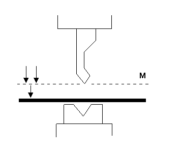
Muto
Punto della sequenza in cui l'asse Y passa dalla velocità di chiusura rapida alla velocità di pressatura. Viene programmato qui come valore di posizione dell'asse Y. Il valore programmato è il punto dell'asse Y sopra il foglio.
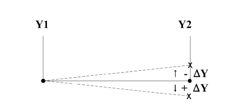
Parallelo
Differenza tra il cilindro sinistro e quello destro (Y1 e Y2). Se positivo, il lato destro è più basso. Se negativo, il lato destro è più alto. Il valore programmato è attivo al di sotto del punto di serraggio.
Apertura
Questo parametro determina una certa apertura di spazio tra il punzone e la matrice dopo la piegatura. Un valore positivo indica l'apertura di spazio sopra il valore Mute, un valore negativo sotto il valore Mute.
Quando si desidera limitare il tempo di gestione del prodotto, è possibile programmare un piccolo valore positivo o negativo.
Forza
Forza
Forza programmata applicata durante la pressatura.
Tempo di permanenza
Tempo di mantenimento del punzone nel punto di piegatura.
Decompressione
Distanza di decompressione dopo la flessione per rilasciare la pressione di esercizio dal sistema. La distanza di decompressione può essere facoltativamente impostata su un punto specifico del ciclo. Di default, la distanza di decompressione viene calcolata come il valore minimo richiesto. Facoltativamente, è possibile scegliere tra Mute, il punto di silenziamento calcolato, o Clamp, il punto di serraggio calcolato. Entrambe le opzioni hanno una distanza maggiore di quella calcolata.
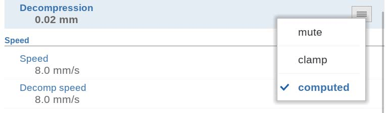
Velocità
Velocità
Velocità di pressatura, velocità dell'asse Y durante la piegatura.
Velocità di decomposizione
La velocità di decompressione è la velocità programmabile del raggio durante la distanza di decompressione.
Funzioni
Attendi il ritiro
In caso di retrazione, lasciare che l'asse Y attenda finché la retrazione non è terminata, sì o no.
No: la retrazione inizia quando l'asse Y supera il punto di serraggio, l'asse Y non si ferma.
Sì: quando l'asse Y raggiunge il punto di serraggio, l'asse Y si ferma e inizia la retrazione. Una volta completata la retrazione, l'asse Y prosegue il suo movimento.
Proprietà del prodotto
Spessore
Programmare lo spessore del foglio.
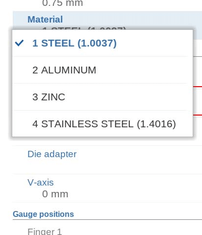
Materiale
Selezione di uno dei materiali programmati, utilizzati per calcolare le profondità di piegatura. Il controllo contiene 4 materiali preprogrammati. In totale, è possibile programmare 99 materiali sul controllo. I materiali possono essere programmati nella pagina Materiali in modalità Impostazioni.
Utensili
Punch
Nome (ID) del punzone selezionato. Tocca per modificarlo o selezionarlo dalla libreria dei punzoni.
Morire
Nome (ID) della matrice selezionata. Tocca per modificarla o selezionarla dalla libreria delle matrici.
Adattatore per punzonatura
Nome (ID) dell'adattatore di perforazione selezionato. Toccare per modificare o selezionare dalla libreria degli adattatori di perforazione. La possibilità di programmare un adattatore dipende dal parametro "Usa adattatore di perforazione" nella modalità Macchina.
Adattatore per matrice
Nome (ID) dell'adattatore di matrice selezionato. Toccare per modificare o selezionare dalla libreria degli adattatori di matrice. La possibilità di programmare un adattatore dipende dal parametro "Usa adattatore di matrice" nella modalità Macchina.
Posizioni del misuratore
Dito (1/2/3/4)
Posizione del dito (contatto), corrispondente alla posizione dell'asse X e alla posizione di appoggio.
Assi ausiliari
Asse ausiliario
Se si dispone di uno o più assi ausiliari (ad esempio un asse X, un asse R o un asse Z), i parametri di questi assi vengono visualizzati qui. Quando si dispone di un asse R1 e di un asse R2, il valore programmato per l'asse R1 viene automaticamente copiato nel valore dell'asse R2. Il valore dell'asse R2 può, se necessario, essere modificato in seguito.
Ritrattare
Distanza di retrazione dell'asse durante la piegatura. La "retrazione del registro posteriore" inizia nel punto di pinzatura.
Velocità
Velocità dell'asse nella piega corrente. La velocità può essere programmata come percentuale della velocità massima possibile.
Supporto parziale
Asse PST
Con questo parametro è possibile attivare o disattivare il supporto del pezzo. Quando è disattivato, il supporto del pezzo rimarrà nella sua posizione zero durante la piegatura.
Posizione R
Altezza del supporto del pezzo prima e dopo la piega. Per impostazione predefinita, l'altezza verrà impostata sulla parte superiore dello stampo (posizione R = 0,00 mm). Disponibile solo se abilitata dal produttore della macchina.
Metodo
In modalità manuale DELEM DA-66S, è possibile controllare come e quando il supporto del pezzo ritorna alla posizione zero dopo aver completato una piega. Le opzioni includono l'impostazione del supporto del pezzo in modo che ritorni quando l'asse Y raggiunge UDP ("Ritorno a UDP") o che il ritorno venga avviato non appena l'asse Y inizia ad aprirsi ("Ritorno all'apertura").
In alternativa, è possibile utilizzare l'opzione "Inclinazione prodotto" per introdurre un'inclinazione aggiuntiva, prevenendo la collisione tra il prodotto e il punzone durante l'apertura dell'asse Y. L'impostazione "Supporto angolare statico" consente al supporto del pezzo di mantenere un angolo fisso, trasformandolo in un tavolo di supporto stabile anziché seguire i movimenti del prodotto. Ogni opzione offre vantaggi unici per l'ottimizzazione delle operazioni della macchina in modalità manuale DELEM DA-66S.
Angolo di inclinazione
L'angolo di inclinazione determina l'entità dello spostamento del supporto del pezzo. Nella parte anteriore della macchina, il supporto si sposta verso l'alto (angolo maggiore), mentre nella parte posteriore si sposta verso il basso (angolo minore). Questa funzione è applicabile quando si utilizza il metodo "Inclinazione prodotto".
Velocità di inclinazione
Specifica la velocità con cui il pezzo si muove fino all'angolo di inclinazione, espressa come percentuale della velocità massima di funzionamento. È rilevante solo quando è selezionata l'opzione "Inclinazione prodotto" nella modalità manuale DELEM DA-66S.
Altezza di inclinazione libera
Se la distanza di decompressione non è sufficiente per il movimento di inclinazione, è possibile programmare un'ulteriore "Limitazione di inclinazione". Questa distanza aggiuntiva è inclusa nella distanza di decompressione programmata, garantendo un funzionamento regolare. L'impostazione della distanza di inclinazione viene utilizzata esclusivamente con il metodo "Inclinazione prodotto" nella modalità manuale del DELEM DA-66S.
Angolo
Angolo statico a cui si sposterà il supporto del pezzo prima della piegatura. Disponibile solo quando è stato selezionato il metodo "Supporto angolare statico".
Velocità
Velocità, espressa in percentuale della velocità massima, con cui il supporto del pezzo si sposta verso l'angolo statico. Disponibile solo se è stato selezionato il metodo "Supporto angolare statico".
velocità di ritorno
Velocità di ritorno del supporto pezzo dopo una piega. Il valore della velocità è programmato come percentuale della velocità massima.
Angolo di arresto di sicurezza
L'angolo a cui il supporto si fermerà durante il movimento di ritorno; il controllo passerà in posizione di arresto. Un ulteriore azionamento del controllo fa sì che il supporto del pezzo ritorni alla sua posizione zero.
Angolo iniziale
Angolo iniziale (tipicamente l'angolo di pre-piegatura di una piega a due stadi) a cui verrà spostato il supporto del pezzo al cambio di passo. Il supporto del pezzo seguirà il movimento non appena l'angolo del prodotto supera l'angolo iniziale del supporto del pezzo. Valido solo per gli assi del supporto del pezzo posizionati davanti alla macchina.
Velocità angolare iniziale
Velocità per spostare il supporto del pezzo all'angolo iniziale. Valido solo per gli assi di supporto del pezzo posizionati davanti alla macchina.
Correzione
La correzione sugli assi di supporto del pezzo in modalità manuale del DELEM DA-66S viene applicata gradualmente durante il processo di piegatura, a partire dal punto di pinzatura. Raggiunta la posizione di piegatura finale, la correzione si adatta al valore programmato. Questi parametri in modalità manuale del DELEM DA-66S possono essere facilmente programmati e modificati secondo necessità. Una volta premuto il pulsante Start, le impostazioni programmate diventano attive.
I parametri in modalità manuale del DELEM DA-66S possono essere programmati e regolati secondo necessità. Una volta premuto il pulsante Start, le impostazioni configurate diventano attive.
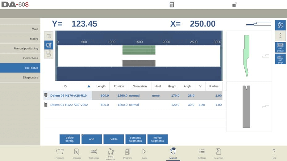
Impostazione dello strumento
La configurazione degli strumenti in modalità manuale DELEM DA-66S è molto simile a quella in modalità automatica. Sebbene ciascuna modalità consenta configurazioni distinte, è possibile scegliere di utilizzare la configurazione degli strumenti della modalità automatica in modalità manuale, ma è necessario prestare attenzione con configurazioni diverse.
Nel menu di configurazione degli utensili in modalità manuale di DELEM DA-66S, è possibile aggiungere, rimuovere o riposizionare facilmente utensili come punzoni, matrici e adattatori. Questo processo rispecchia le principali funzioni di configurazione degli utensili, consentendo regolazioni personalizzate per migliorare le operazioni di piegatura. Inoltre, è possibile segmentare gli utensili durante l'aggiunta, in base alle proprie esigenze specifiche.
Prodotto di spostamento

Nella modalità manuale del DELEM DA-66S, lo spostamento del prodotto è semplificato grazie alla funzione "Sposta prodotto". I punti di aggancio aiutano gli utenti a spostare con precisione il prodotto, facilitando l'allineamento a lato degli utensili o al centro della stazione.
Funzioni chiave per il posizionamento del prodotto:
- Salta a sinistra: Spostare il prodotto su una diversa combinazione di set di strumenti sulla sinistra.
- Salta a destra: Spostare il prodotto su una diversa combinazione di set di strumenti sulla destra.
- Sposta a sinistra: Spostare il prodotto di 1 millimetro verso sinistra all'interno dello stesso set di strumenti.
- Sposta a destra: Spostare il prodotto di 1 millimetro verso destra all'interno dello stesso set di strumenti.
L'utilizzo di queste funzioni nella modalità manuale DELEM DA-66S garantisce un controllo preciso sul posizionamento del prodotto, migliorando sia la flessibilità che la precisione nelle operazioni.
Parametri di programmazione e viste
Nella modalità manuale DELEM DA-66S è possibile programmare i parametri singolarmente, ciascuno dei quali è visualizzato insieme a simboli e colori di sfondo per una facile identificazione.

Un simbolo informativo indica una modifica dovuta a un input recente, evidenziando le regolazioni apportate.

Un simbolo a forma di stella avvisa quando il valore di un parametro differisce dai calcoli del controllo, utile per impostazioni deliberate o limitate da vincoli.

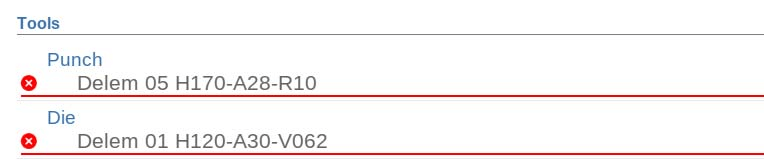
Gli errori vengono segnalati con un simbolo di errore se un valore non è compatibile con il programma corrente, ad esempio una piega di orlatura impostata senza gli strumenti appropriati.
Il lato destro dello schermo consente di accedere a più viste, tra cui Principale, Macro, Posizionamento manuale, Correzioni e Diagnostica, migliorando le capacità di controllo e monitoraggio dell'utente nella modalità manuale DELEM DA-66S.

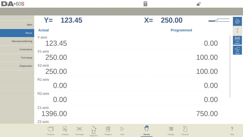
Macro
Nella modalità manuale del DELEM DA-66S, la vista Macro mostra i valori degli assi di grandi dimensioni sullo schermo, facilitandone la lettura a distanza. Questa funzione è particolarmente utile quando si lavora da remoto tramite il pannello di controllo.
Esecuzione di un'operazione di piegatura sicura ed efficiente
Procedure di movimento manuale degli assi
Per spostare manualmente gli assi in sicurezza, utilizzare il volantino del DELEM DA-66S. Assicurarsi che la macchina sia ferma durante il riposizionamento degli assi ausiliari, mentre l'asse Y richiede che il sistema sia attivo e che siano soddisfatte determinate condizioni, come l'attivazione della funzione di "regolazione".
Dopo aver toccato Posizionamento manuale nella schermata principale della modalità manuale, viene visualizzata la seguente schermata:
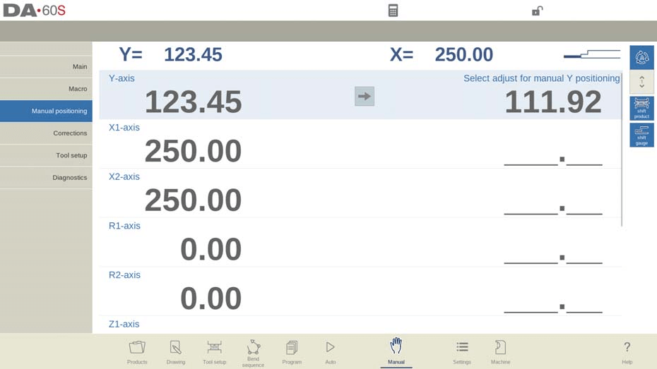
Nella modalità manuale del DELEM DA-66S, è possibile spostare manualmente gli assi utilizzando il volantino. I passaggi variano a seconda del tipo di asse che si sta regolando.
Per assi ausiliari, assicurarsi che la macchina sia ferma (LED del pulsante Stop acceso). Selezionare l'asse del registro posteriore che si desidera spostare e utilizzare la rotella per riposizionarlo.
Con il asse YIl posizionamento manuale è simile, ma richiede che la macchina sia avviata (LED del pulsante di avvio acceso). Inoltre, la funzione "regola" deve essere attivata (controllare i messaggi in alto a destra se non lo è). Assicurarsi che l'asse Y sia al di sotto del punto di silenzio e che un comando di pressatura sia stato immesso nel CNC.
Seguendo queste procedure nella modalità manuale DELEM DA-66S, è possibile gestire in modo sicuro ed efficace gli assi della macchina.
Utilizzo della modalità di insegnamento
Per insegnare in modo efficiente al controllo in modalità manuale DELEM DA-66S una posizione rilevata regolando manualmente un asse, seguire questa semplice procedura. Utilizzare il volantino per spostare un asse nella posizione desiderata. Per salvare questa posizione, toccare il nome dell'asse nella colonna Programmato; il valore effettivo dell'asse da sinistra verrà quindi inserito nel campo dell'asse programmato a destra.

Tornando alla schermata standard della modalità manuale DELEM DA-66S, troverete il parametro dell'asse aggiornato con il valore appena appreso.
Monitoraggio e diagnostica per operazioni sicure
Correzioni
Nella modalità manuale del DELEM DA-66S, è possibile visualizzare e verificare le correzioni delle pieghe come una singola riga, in modo simile alla modalità automatica. Queste correzioni e le voci nel database delle correzioni sono fondamentali per risultati di piega accurati. L'accesso al database consente di modificare e ottimizzare queste correzioni, il che può anche essere utile nei processi di piegatura di prova.

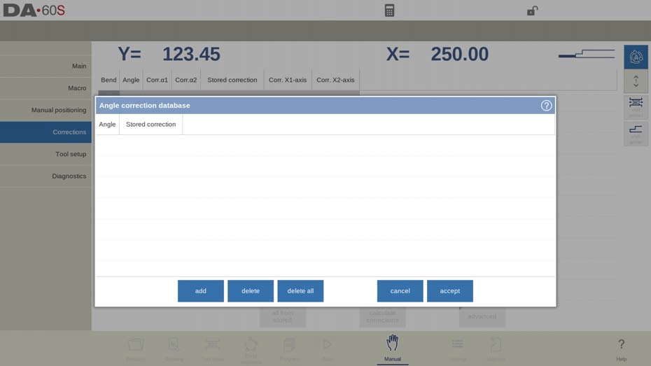
IL tolleranza di piegatura La funzione "Gestione della tolleranza di piega" in modalità manuale DELEM DA-66S consente agli utenti di immettere dati nella tabella delle tolleranze di piegatura. Aggiungendo solo le correzioni necessarie in base ai parametri di piegatura attivi, è possibile calcolare la tolleranza di piegatura dalla differenza tra i valori programmati e quelli misurati. Per attivare questa funzione, passare alla modalità Impostazioni.
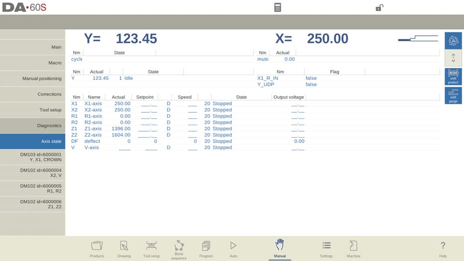
Diagnostica e monitoraggio in tempo reale
In modalità manuale DELEM DA-66S, la funzione Diagnostica fornisce una visione completa dello stato degli assi della macchina. Questa funzionalità consente agli operatori di monitorare in tempo reale lo stato di ciascun asse durante un ciclo di piegatura. L'accesso alla Diagnostica consente di osservare il comportamento dei controlli, favorendo operazioni efficienti e sicure.
Monitoraggio dello stato IO
La modalità manuale DELEM DA-66S include una funzione di stato IO dettagliata, che offre informazioni sullo stato attuale di tutti gli ingressi e le uscite. Questo monitoraggio in tempo reale è fondamentale per valutare le prestazioni della macchina e risolvere rapidamente eventuali problemi durante il funzionamento.

Vista IO ingrandita
Per un'osservazione più approfondita, la funzione Zoomed IO in modalità manuale del DELEM DA-66S consente di selezionare fino a otto pin per una visualizzazione ingrandita. Questa funzionalità facilita il monitoraggio a distanza, garantendo la possibilità di tracciare facilmente ingressi e uscite critici.
Modalità di piegatura di prova per la precisione
La modalità manuale DELEM DA-66S include una funzione di piegatura di prova progettata per ottimizzare le operazioni di piegatura.

Una volta attivati, gli assi rimangono nelle loro posizioni di retrazione dopo il ciclo di piegatura iniziale, con il supporto del pezzo che mantiene il suo angolo, se abilitato. Questa modalità interrompe qualsiasi cambio di passo.
Una volta completata la piega di prova, l'asse Y si ferma in corrispondenza del punto UDP, consentendo agli operatori di misurare gli angoli con precisione e di applicare le correzioni necessarie. Dopo le regolazioni, la piega può essere rieseguita. Il supporto del pezzo riprende a seguire l'asse Y quando torna nella sua posizione originale. Ciò garantisce correzioni precise e una maggiore precisione di piegatura.
Domande frequenti (FAQ)
Come posso garantire la sicurezza durante l'utilizzo del DELEM DA-66S in modalità manuale?
Seguire sempre le linee guida di sicurezza del produttore, assicurarsi che la macchina sia correttamente calibrata e ricontrollare tutte le posizioni degli assi prima di iniziare qualsiasi operazione. Sono essenziali dispositivi di sicurezza adeguati e una formazione adeguata.
Come posso mantenere prestazioni ottimali del mio DELEM DA-66S in modalità manuale?
La manutenzione regolare è fondamentale. Controllare la macchina ogni 500 ore, ispezionare i componenti essenziali, pulire il sistema e lubrificare le parti mobili secondo le istruzioni del produttore.
Come si applicano le correzioni all'angolo di piegatura nella modalità manuale DELEM DA-66S?
Misura l'angolo corrente dopo una curva, quindi regola i parametri Corr.α in modalità manuale. Ciò consente di programmare le correzioni necessarie e ottenere con precisione gli angoli desiderati.
Cosa devo fare se gli assi non tornano nella posizione originale dopo una piega di prova?
Dopo la piega di prova, assicurarsi che l'asse Y sia sul punto di piegatura (UDP). Se il supporto del pezzo non segue la piega, verificare che sia abilitato e verificare eventuali ostruzioni o disallineamenti nella configurazione.
Conclusione
Per utilizzare il DELEM DA-66S in modalità manuale in modo sicuro ed efficiente è necessario comprenderne le caratteristiche e sottoporlo a manutenzione regolare. Seguire le linee guida sopra riportate e risolvere i problemi più comuni può migliorare le prestazioni e la longevità della macchina. Per un supporto dettagliato o ulteriori informazioni, contattate il nostro team o consultate la documentazione aggiuntiva sul nostro sito web.


