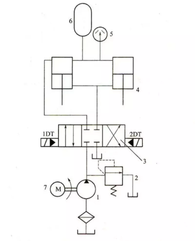
Schema del sistema idraulico della macchina idraulica

Nella mia esperienza lavorativa con macchine idrauliche, comprendendo il sistema idraulico Il diagramma è fondamentale per un funzionamento e una manutenzione efficaci. Questo diagramma funge da rappresentazione visiva dei componenti del sistema e delle loro interconnessioni, aiutando gli operatori a risolvere i problemi e ottimizzare le prestazioni. Nel corso degli anni, ho imparato a interpretare questi diagrammi, il che ha notevolmente migliorato la mia capacità di diagnosticare i problemi e implementare soluzioni. In questo articolo, esplorerò gli elementi chiave del diagramma del sistema idraulico di una macchina idraulica, fornendo spunti che possono aiutare sia gli operatori alle prime armi che quelli esperti a comprendere e lavorare meglio con i sistemi idraulici.
1. Seleziona il circuito di base
● Circuito di controllo della velocità: poiché il sistema idraulico ha una bassa potenza e un carico positivo, viene selezionato il circuito di controllo della velocità della valvola a farfalla in ingresso dell'olio. Per una buona fluidità a bassa velocità e caratteristiche di carico a velocità elevata, è possibile selezionare la velocità della valvola regolatrice di velocità e impostare la contropressione sul circuito del cilindro idraulico.
●Circuito di alimentazione dell'olio della pompa: poiché la differenza tra la velocità di lavoro e la velocità di movimento rapido è molto diversa, per l'alimentazione dell'olio viene utilizzata una doppia pompa.
●Circuito di commutazione della velocità e circuito veloce: poiché la differenza tra la velocità di lavoro e la velocità di avanzamento veloce è molto diversa, per rendere la commutazione fluida, viene selezionato il circuito di commutazione controllato dalla valvola di corsa. Il movimento veloce è ottenuto tramite un circuito differenziale.
●Circuito di commutazione: per garantire la fluidità, utilizzare una valvola di controllo direzionale elettroidraulica. Per ottenere l'arresto in folle e il collegamento differenziale del cilindro idraulico, viene utilizzata una valvola a cinque vie a tre posizioni.
●Circuito di controllo della pressione: l'uso del circuito di carico a bassa tensione di tipo valvola di inversione riduce il consumo di energia e la struttura è relativamente semplice.
2. Selezione del circuito idraulico
Per la sintesi del ciclo di base selezionato sono necessari adattamenti, modifiche e fusioni.
●Per evitare che le linee di aspirazione e di ritorno vengano forate durante l'alimentazione del lavoro e per accedere alla valvola di ritegno.
Per ottenere un avanzamento rapido differenziale, è necessario installare una valvola di sequenza di controllo idraulico sulla linea di ritorno per impedire che l'olio rifluisca nel serbatoio.
Il principio di funzionamento dell'intero sistema idraulico dopo la fusione è il seguente: