


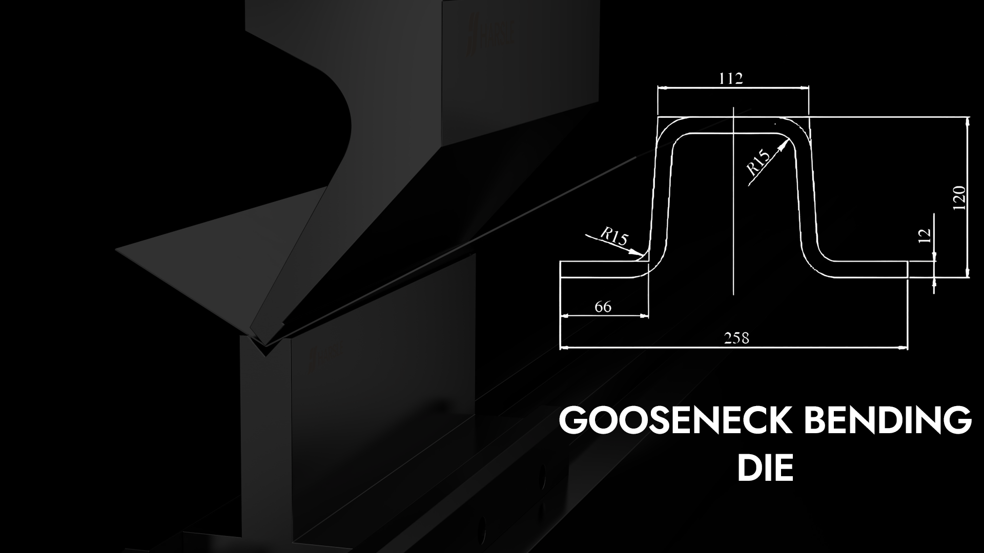
Projekt matrycy do gięcia typu „gęsia szyja” i analiza intensywności
Dzięki szerokiemu zastosowaniu matryca do gięcia typu „gęsia szyja” W dziedzinie tłoczenia, koszty produkcji zakrzywionych elementów formowanych są znacznie niższe. Jednocześnie problem uszkodzeń form, występujący podczas stosowania matrycy gnącej typu „gęsia szyja”, stał się częstym problemem bezwładnościowym w warsztacie produkcyjnym. Uszkodzenia te są spowodowane niewystarczającą wytrzymałością formy i nieracjonalną konstrukcją formy.
1. Analiza procesu części
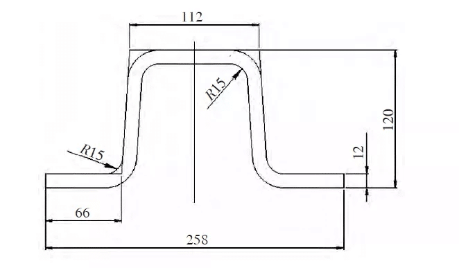
Biorąc za przykład kolumnę boczną wagonu towarowego, proces projektowania i analiza sił matryca do gięcia typu „gęsia szyja” są szczegółowo opisane. Rysunek 1 przedstawia przekrój poprzeczny słupa bocznego wagonu kolejowego przeznaczonego do transportu eksportowego. Grubość wynosi 12 mm. Materiał to Q450NQR1. Stal o wysokiej wytrzymałości i odporności na korozję przeznaczona do wagonów kolejowych ma długość 2530 mm. Przebieg procesu jest następujący: śrutowanie, malowanie → cięcie → cięcie → prostowanie → gięcie → magazynowanie.
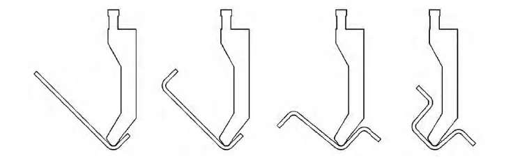
Jak pokazano na rys. 2, proces gięcia jest podzielony na 4 etapy. Podczas etapu 4., tryb gięcia typu „gęsia szyja” odgrywa rolę. Dlatego w procesie projektowania matrycy do gięcia typu „gęsia szyja”, projektowanie parametrów matrycy odbywa się głównie zgodnie z etapem 4.
2. Obliczanie siły zginającej
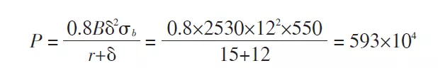
P——całkowita siła zginająca, N
B——szerokość gięcia, mm
δ——grubość materiału, mm
σb——wytrzymałość na rozciąganie, MPa
R——wewnętrzny promień gięcia, mm
Siła gięcia niezbędna do obliczenia części wynosi 5930 kN, co oznacza, że matryca gnąca musi wytrzymać nacisk 5930 kN wywierany przez maszynę gnącą.
3. Zasada projektowania formy do gięcia typu „gęsia szyja”
Jak pokazano w kroku 4 gięcia na rys. 2, jeśli nie ma elementu struktury gęsiej szyi, obrabiany przedmiot będzie kolidował z trybem gięcia podczas procesu gięcia, przerywając tym samym gięcie i uniemożliwiając formowanie przedmiotu. Zasada projektowania formy z gęsią szyją polega na wykorzystaniu elementu gęsiej szyi formy, aby uniknąć metody projektowania formy, w której obrabiany przedmiot koliduje z formą podczas procesu formowania.
4. Określanie parametrów matrycy gnącej typu „gęsia szyja”
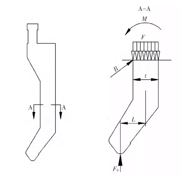
Jak pokazano na rys. 3, schematyczny diagram matrycy do gięcia typu „gęsia szyja”, w której mimośród L i wymiar szerokości t są kluczowymi parametrami wpływającymi na wytrzymałość matrycy. Aby sprostać wymaganiom formowania części, początkowa szerokość gęsiej szyjki wynosi 50 mm, a mimośród L powinien wynosić (t/2+2,5) mm, gdzie t to wymiar szerokości sekcji formy najbardziej oddalonej od środka nacisku, tj. t = 50 mm.
5. Analiza intensywności
Przeprowadzono analizę wytrzymałościową części gęsiej szyi formy. Oprócz ciśnienia z giętarki, forma jest poddawana momentowi zginającemu spowodowanemu ciśnieniem w części gęsiej szyi. Wybierz przekrój AA gęsiej szyi do analizy wytrzymałościowej i wykonaj obliczenia równania kolumny: analiza wytrzymałościowa części gęsiej szyi formy, oprócz ciśnienia z giętarki, forma jest również poddawana ciśnieniu w części gęsiej szyi. Moment zginający. Jak pokazano na rys. 4, analiza stanu naprężenia AA niebezpiecznej sekcji gęsiej szyi pokazuje, że szerokość sekcji wynosi t, pionowa odległość między środkiem nacisku giętarki a środkiem ciężkości sekcji AA wynosi L, a nacisk dostarczany przez giętarkę do matrycy gnącej wynosi F, siła F0 reakcji przedmiotu obrabianego na matrycę gnącą, moment zginający sekcji wynosi M i istnieje możliwość pęknięcia w punkcie B sekcji. Po przeprowadzeniu analizy, narysowano uproszczony diagram stanu sił przekroju pokazanego na rys. 4AA.
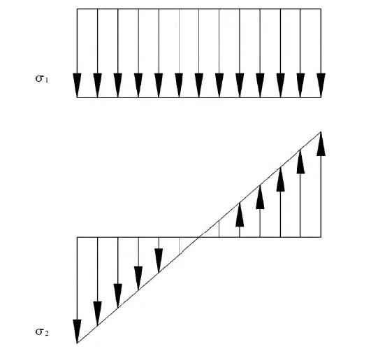

σ1——naprężenie generowane przez siłę zewnętrzną F0
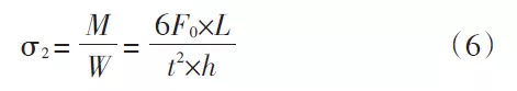
σ2——naprężenie generowane przez moment zginający
W równaniu (5) W jest współczynnikiem przekroju zginanego. Ponieważ przekrój AA jest prostokątem o wysokości t i długości h, zatem w = t2h/6.
Ze wzoru (2) M=F0×L, a następnie podstaw W i M do wzoru:
t——grubość przekroju A, mm
L——odległość pionowa między środkiem nacisku giętarki a środkiem ciężkości przekroju A, mm
h——długość matrycy gnącej, mm
Podstawienie wartości σ1 i σ2 do równania (3) daje σ3 w postaci:
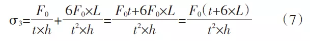
σ3 — suma momentu zginającego i naprężenia wytworzonego przez siłę M i siłę zewnętrzną F0
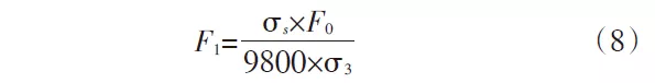
F1——Maksymalne naprężenie, jakie może wytrzymać niebezpieczny odcinek AA formy
δs — granica plastyczności materiału o kształcie zginanym
Podstawiając wynik σ3 wzoru (7) do wzoru (8) w celu uzyskania F1
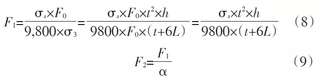
We wzorze (9) α jest współczynnikiem bezpieczeństwa, który zazwyczaj przyjmuje wartość od 1,1 do 1,2. W tym obliczeniu przyjmuje się α = 1,15, a wartości α i F1 podstawia się do wzoru (9):
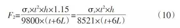
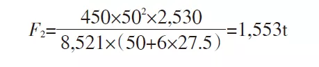
δs = 450 MPa, h = 2530 mm, t = 50 mm, L = 27,5 mm, podstawiając do wzoru (10), wartość F2 wynosi 1553 t, co oznacza, że zaprojektowany profil AA o dużej sile zginającej może wytrzymać naprężenie 1553 t. Wartość ta jest znacznie większa niż siła zginająca podczas formowania elementu, co pozwala spełnić wymagania dotyczące formowania elementu.

6. Optymalizacja strukturalna
Zgodnie z powyższymi wynikami obliczeń, naprężenie niebezpiecznego przekroju AA wynosi 15530 kN, co jest wartością znacznie większą od siły zginającej formowanego przedmiotu obrabianego wynoszącej 5930 kN, co pozwala na spełnienie wymagań formowania przedmiotu obrabianego.
Aby jednak jeszcze bardziej zmniejszyć pracochłonność operatora i obniżyć koszty produkcji formy, konieczna jest optymalizacja konstrukcji formy, aby mogła ona spełniać wymagania realizacji produktu, zmniejszając
intensywność pracy operatora i obniżenie kosztów produkcji formy.
Zgodnie ze wzorem (10) naprężenie występujące w niebezpiecznym przekroju AA jest związane z granicą plastyczności σs materiału formy, grubością t przekroju A, długością h trybu gięcia i pionową odległością L między środkiem nacisku maszyny do gięcia a środkiem ciężkości przekroju A. Ponieważ materiał formy zwykle się nie zmienia, σs jest wartością stałą; długość przedmiotu obrabianego wynosi 2530 mm, co również jest wartością stałą L = t/2+2,5; zatem zmienną we wzorze jest tylko t, a wartość t jest stopniowo optymalizowana:
Wykonaj ponowne obliczenia, zmieniając wartość t z 50 na 30:
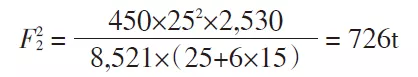
Przelicz wartość t z 30 na 25 w celu ponownego obliczenia:
Wykonaj ponowne obliczenia, zmieniając wartość t z 25 na 20:
Zgodnie z powyższymi wynikami obliczeń, F32 jest mniejsze niż maksymalna siła gięcia formowanego elementu, F12 i F22 są większe niż maksymalna siła gięcia formowanego elementu, ale koszt produkcji formy jest niski, co ułatwia operatorowi montaż i demontaż formy. Ostatecznie ustalono, że niebezpieczny odcinek AA formy ma szerokość 25 mm. Grubość części roboczej pozostałej części formy została zaprojektowana zgodnie z 25 mm. Krzywizna gęsiej szyi jest nadmiernie zakrzywiona, aby uniknąć lokalnej koncentracji naprężeń. Rozmiar interfejsu formy i urządzenia można zaprojektować zgodnie z mechanizmem zaciskowym urządzenia.
7. Weryfikacja efektów
Praktyka dowiodła, że forma jest w stanie wytrzymać naprężenia występujące w giętej części, a jej sztywność i wytrzymałość spełniają rzeczywiste wymagania produkcyjne. Aby dostosować się do współczesnych, wysokowydajnych, niskokosztowych i dynamicznych procesów produkcji części, projekt formy, jako źródło kosztów, stanowi istotny składnik kosztów produkcji. Wzór i proces obliczeniowy można wykorzystać i zastosować w procesie projektowania form typu „gęsia szyja”.
8. Wnioski
Niebezpieczna część matrycy gnącej typu „gęsia szyja” znajduje się najdalej od środka nacisku. W zależności od materiału i konstrukcji formy, wytrzymałość niebezpiecznej części jest proporcjonalna do jej grubości.


