Como dominar a máquina de laminação em pouco tempo
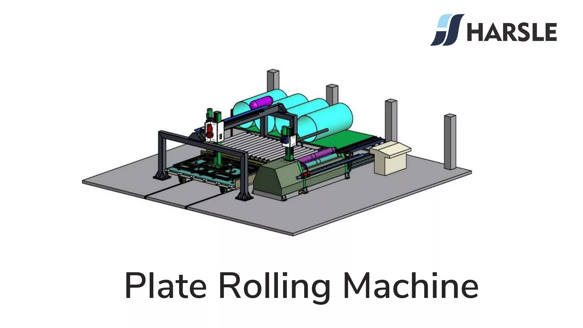
O que é máquina de laminação
Uma laminadora, também conhecida como laminadora ou laminadora de rolos, é um dispositivo usado na metalurgia para moldar e conformar metais, passando-os entre dois ou mais rolos rotativos. Esse processo, conhecido como laminação, é um dos métodos mais comuns de conformação de metais, permitindo a criação de chapas, placas, barras ou outros formatos uniformes a partir de estoques metálicos. As laminadoras são essenciais em setores como automotivo, construção civil, aeroespacial e manufatura.
Através do rolo rotativo, o método de dobrar a chapa sob a ação e o atrito do rolo é chamado de laminação. Na produção, o método mais utilizado é a dobradeira de três rolos.
Princípios básicos da máquina de laminação
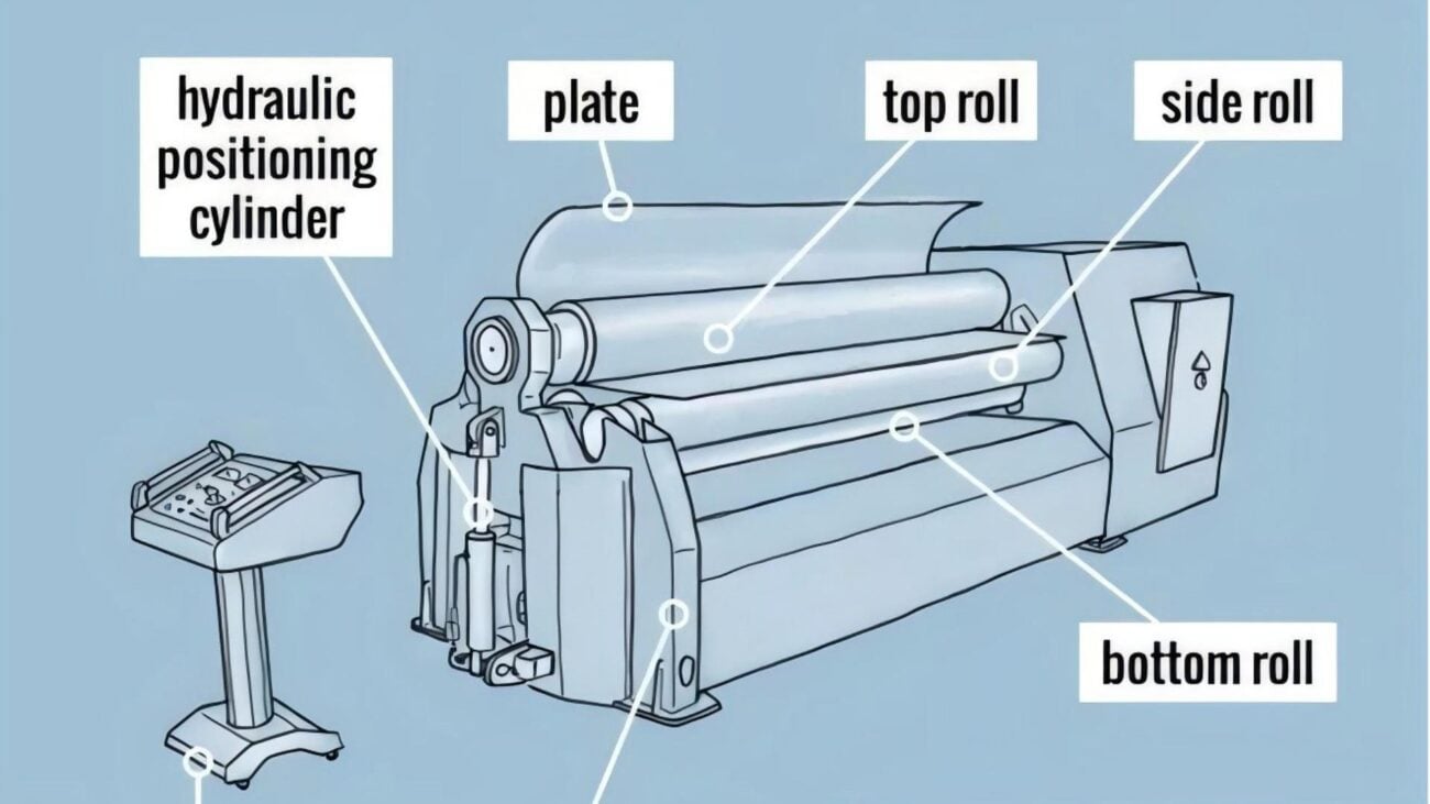
O princípio básico de máquina de laminação é mostrado na figura abaixo. Se a peça bruta for colocada sobre o rolo inferior em repouso, sua superfície inferior estará em contato com os pontos mais altos b e c do rolo inferior, e a superfície superior estará em contato com o ponto mais baixo a do rolo superior. Neste momento, a distância vertical entre os rolos superior e inferior é exatamente igual à espessura do material. Quando o rolo inferior não se move, o rolo superior desce, ou o rolo superior não se move, e o rolo inferior sobe, a distância é menor que a espessura do material. Se os dois rolos forem laminados continuamente, a peça bruta será lisa em todas as faixas de laminação. Como as duas extremidades da peça bruta não podem ser laminadas, elas ainda são retas. Ao formar peças, devemos tentar eliminá-las.

A curvatura da chapa após a laminação depende da posição relativa do eixo do rolo, da espessura da chapa e das propriedades mecânicas. Conforme mostrado na figura abaixo, a relação entre elas pode ser expressa aproximadamente pela seguinte fórmula:

As distâncias relativas H e B entre os rolos são ajustáveis para atender às necessidades da curvatura da peça. Como é mais conveniente alterar H do que B, geralmente se obtêm curvaturas diferentes alterando H. Como é difícil calcular e determinar a quantidade de rebote do material da folha com antecedência, a expressão relacional acima não pode marcar com precisão o valor H necessário, que serve apenas como referência durante o rolo inicial. Na produção real, o método de teste é amplamente adotado, ou seja, após a posição do rolo superior ser ajustada aproximadamente com base na experiência, o papel é testado gradualmente até que a curvatura necessária seja atingida.
Operação da máquina de laminação
As etapas para operar o três eixos máquina de laminação são os seguintes: primeiro, levante o rolo superior e ajuste a distância entre os rolos inferiores de acordo com a espessura da peça bruta. A distância entre os rolos inferiores deve ser a menor possível quando a força de flexão do rolo superior for permitida. Geralmente, é razoavelmente fixada de acordo com a espessura da peça bruta. Quando a espessura é de 4 mm, o espaçamento é de 90 a 100 mm e, quando a espessura é de 4 a 6 mm, o espaçamento é de 110 a 120 mm. Coloque a peça bruta no rolo inferior, cubra os dois rolos inferiores e, em seguida, abaixe o rolo superior de acordo com os requisitos do raio de curvatura e dobre a peça bruta localmente e, em seguida, gire a base do rolo para girar o rolo, e a peça bruta é automaticamente enviada para dobrar e formar. Levante, suba os rolos e, finalmente, remova as peças.
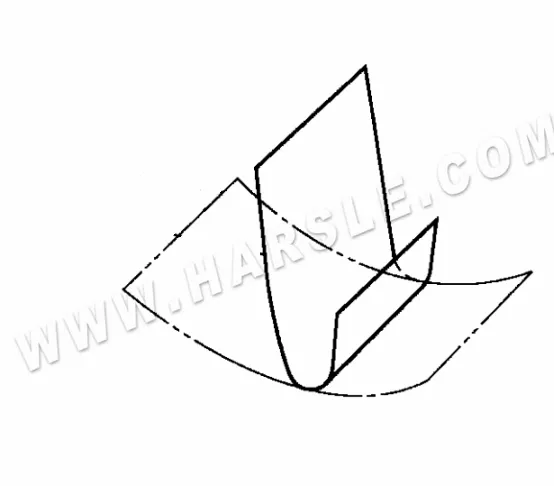
Na laminadora simétrica de três eixos, alterando a posição mútua dos três rolos, podem ser laminadas quatro peças típicas: formato simples de curvatura igual, formato simples de curvatura variável, cone de curvatura igual e cone de curvatura variável, conforme mostrado na figura a seguir. Ao dobrar, a conformação única deve ser evitada ao máximo para evitar dobras excessivas. Isso causará dificuldades em operações repetidas. Após cada dobra, a distância de abaixamento do rolo superior é geralmente de cerca de 5 a 10 mm. Os principais pontos das operações de dobra de rolos de várias formas são os seguintes.

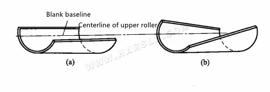
1. Ao laminar peças cilíndricas (cilíndricas) com curvatura igual, isso pode ser alcançado desde que o rolo superior não se mova para cima e para baixo durante o processo de dobra e os três rolos estejam paralelos entre si. A curvatura precisa passar por vários rolos de teste, do fino ao retificado, antes de finalmente atingir os requisitos. Vale ressaltar que a peça bruta deve ser colocada na vertical durante a alimentação, caso contrário, as peças laminadas serão distorcidas, como mostrado na figura (b). É melhor traçar uma linha de referência ao dobrar. Ao dobrar, faça a linha de referência coincidir com o eixo do rolo superior antes de iniciar a dobra, como mostrado na figura (a). Isso é particularmente importante para a dobra de chapas grandes e grossas. Porque o reparo posterior desse tipo de peça não é apenas grande, mas também bastante difícil.
Laminação de peças simples com curvatura igual
2. Durante o processo de laminação, os três rolos permanecem paralelos entre si, e as posições para cima e para baixo dos rolos superiores podem ser alteradas a qualquer momento para a laminação de peças com diferentes graus de curvatura. Para a peça cilíndrica mostrada no diagrama de laminação, R1>R2>R3>R4>Rs na figura. O método utilizado na produção consiste em aproximar esta peça como sendo composta por várias formas cilíndricas com diferentes raios R, prensando o raio R em seções, que são laminadas sucessivamente de acordo com o raio de curvatura, do maior para o menor. As etapas de toda a operação são as seguintes.
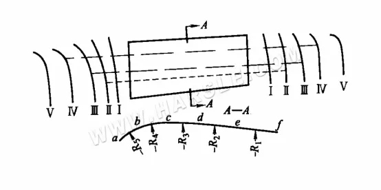
Laminação de peças cilíndricas de curvatura variável
Processo I: Ajuste a posição do rolo superior com R1 e role a chapa da extremidade a até a extremidade f, de modo que o raio de curvatura da seção ef atenda aos requisitos.
Processo II: Ajuste o rolo inferior com R2, role da extremidade a até a extremidade e, de modo que o raio de curvatura da seção de atenda aos requisitos. Quando o rolo superior se aproxima do ponto e, ele sobe lenta e moderadamente para fazer uma transição suave e evitar que bordas e cantos apareçam entre R1 e R2.
De a para d, de a para c, de a para b para completar o outro processo III para processar V.
Na produção em massa, para aumentar a eficiência, após a conclusão dos procedimentos de todo o lote de peças, os procedimentos subsequentes são realizados. É melhor inspecionar cada parte de cada processo de acordo com o modelo ou molde, para não afetar o processo subsequente.
3. Laminação de peças cônicas Teoricamente falando, durante o processo de dobra, os dois eixos do rolo inferior são mantidos paralelos, e o eixo do rolo superior é inclinado e não se move para cima e para baixo para que as peças cônicas com curvatura igual possam ser laminadas. Os dois eixos do rolo inferior são mantidos paralelos, e o eixo do rolo superior é inclinado e movido para cima e para baixo para laminar peças cônicas com graus variados de curvatura. É necessário fazer as duas extremidades da peça bruta alimentarem entre os rolos em velocidades diferentes para laminar as peças cônicas com curvatura igual ou variável que atendam aos requisitos. Isso ocorre porque a curvatura das duas extremidades desse tipo de peça é diferente, e o comprimento de desdobramento também é diferente. Portanto, ao dobrar, é necessário ter velocidades de dobra diferentes em ambas as extremidades. A velocidade na extremidade com a curvatura maior deve ser mais lenta, e a velocidade na extremidade com a curvatura menor deve ser mais rápida. Como o material da chapa é submetido à pressão de laminação de três rolos simultaneamente durante a dobra, e os rolos geralmente são cilíndricos, é impossível obter várias velocidades diferentes simultaneamente. Para resolver esse problema, a chapa precisa ser dividida em várias seções na direção da dobra e realizar a dobra segmentada.
Os métodos comumente usados para laminação de peças cônicas na produção incluem principalmente o método de alimentação retangular, o método de laminação particionada e o método de alimentação rotativa, o método de desaceleração de boca pequena e assim por diante. A figura abaixo mostra o método de dobra do rolo de alimentação retangular para peças cônicas. Durante a operação: Primeiro, alimente o material de acordo com a linha central retangular AEFD OH mostrada na Figura (b) e desenrole a forma cilíndrica em ambos os lados, de modo que a seção do meio role para fora da retidão da barra de ônibus. Neste momento, os quatro cantos são expandidos, especialmente os dois lugares A e D. Para destacar, como mostrado na figura (c). Em seguida, role ambos os lados com posicionamento e alimentação AB e CD, de modo que os dois lados sejam enrolados, e a retidão da geratriz é desenrolada para que a parte cônica seja enrolada para fora, como mostrado na Figura (d). Em essência, ela é laminada em três áreas. Ao laminar esse tipo de peça, a peça bruta deve ser colocada na mesma posição que o comprimento do rolo. Se ele se mover para a esquerda e para a direita, a curvatura da parte laminada não atenderá aos requisitos.
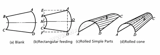
Laminação de avanço retangular de peças cônicas
A figura abaixo mostra o método de laminação por zona de peças cônicas. Operação: Primeiramente, a placa do cone de laminação é dividida em seções, conforme mostrado na figura. Ao laminar, alinhe o rolo superior com a linha de 5-5 pés para dobrar até que a extremidade maior atinja 4; em seguida, enrole. Alinhe a roda com a linha de 4-4 pés para rolar, até que a extremidade maior atinja 3 e, por fim, siga os passos acima para completar a dobra do rolo em cada zona.
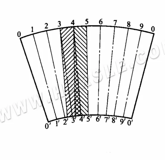
Laminação de partição de peças cônicas
O objetivo da segmentação mencionada é reduzir a diferença no comprimento da curva em ambas as extremidades do segmento, de modo que a parte cônica possa ser laminada de forma semelhante a uma peça cilíndrica. Em seguida, a peça bruta é girada entre cada parte para compensar a diferença de velocidade entre as duas extremidades, garantindo a laminação. A precisão da peça. A prática demonstrou que quanto menor a área, ou seja, quanto mais vezes a peça bruta gira durante a laminação, melhor a qualidade, mas não é necessário dividi-la demais. A determinação deve ser feita de acordo com o tamanho da peça e o tamanho do cone.
4. A figura abaixo mostra o dispositivo para laminar uma superfície cônica pelo método de alimentação rotativa. Para laminar o material em forma de leque em uma superfície cônica, o material em forma de leque deve ser girado e alimentado em torno de 0 horas, e a linha central dos rolos laterais deve ser ajustada para incliná-lo. Por esse motivo, na ranhura em forma de T da mesa de trabalho adicional em frente à máquina de dobrar chapas, uma roda-guia disposta em forma de arco é instalada para forçar o material em forma de leque a girar em torno do ponto O. A função da roda-guia final é fazer com que a parte final do material se desprenda da roda-guia frontal e ainda seja capaz de girar, alimentar e enrolar em um cone.

Diagrama esquemático do dispositivo de alimentação rotativa
A figura abaixo mostra o dispositivo para laminação de uma superfície cônica com um método de desaceleração de boca pequena. Ajuste o rolo superior para uma posição inclinada e adicione um dispositivo de desaceleração na extremidade de boca pequena para aumentar a resistência de avanço da extremidade de boca pequena da chapa, de modo que a velocidade de avanço da boca pequena seja reduzida e a chapa em forma de leque gire e role durante a alimentação.
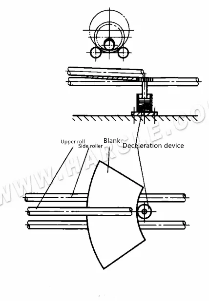
Diagrama esquemático do dispositivo de desaceleração de boca pequena
5. A laminação de peças com raio de curvatura pequeno afeta aquelas com raio de curvatura de seção relativamente pequeno, e às vezes não é possível conformá-las completamente em uma laminadora de três eixos. A dobragem desse tipo de peça geralmente requer dois processos, como mostrado na figura. Primeiro, a curvatura necessária é desenrolada na mesa de laminação de três eixos para que ambos os lados atendam aos requisitos e, em seguida, a curvatura central é dobrada na prensa dobradeira com a matriz de dobra, para que ela finalmente atenda aos requisitos.
Laminação de peças com pequeno raio de curvatura
6. A placa lateral da escada em espiral é uma parte do formato cilíndrico, e seu método de laminação é o mesmo do cilindro, mas o ângulo entre a colocação do rolo na placa e o rolo da placa antes da crimpagem deve ser o ângulo da espiral da escada em espiral. O ângulo de elevação e o ângulo de colocação durante a laminação podem ser medidos com um modelo. O ângulo do modelo é β≈180°-a°, conforme mostrado na figura.
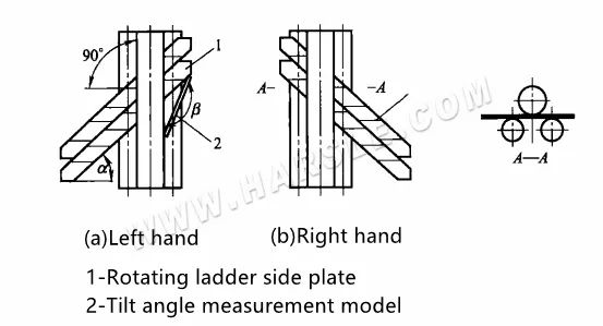
1-Placa lateral da escada giratória
2-Modelo de medição do ângulo de inclinação
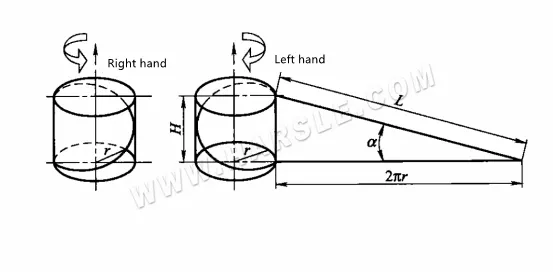
A laminação, dependendo do comprimento da chapa lateral da escada em espiral e das condições específicas da laminadora de chapas, pode ser realizada em um único bloco H ou em vários blocos simultaneamente. O ângulo de hélice a é calculado de acordo com a = arctan H/2πr, e o significado de cada símbolo na fórmula é mostrado na figura.
Precauções para a operação da máquina de laminação de chapas
Ao operar uma máquina de dobrar de três eixos, os seguintes pontos devem ser observados.
1. Se os dois rolos inferiores da base de laminação forem os eixos de acionamento, a força de mordida entre os rolos e a peça bruta é pequena, e a peça bruta desliza facilmente e não se move, portanto, a curvatura de um rolo não pode ser muito grande. Se a peça tiver uma curvatura grande, ela deve ser laminada repetidamente várias vezes, a cada vez que o rolo superior é abaixado em uma quantidade adequada, e a curvatura da peça é gradualmente aumentada. Se os três rolos forem todos eixos de acionamento, uma curvatura maior pode ser laminada de uma só vez.
2. Ao laminar uma chapa fina de 4 mm ou menos em uma laminadora assimétrica de três eixos, onde todos os três rolos são eixos ativos, a posição dos rolos pode ser ajustada de acordo com a curvatura da peça, iniciando a rotação e enviando a chapa diretamente para laminação. A borda da chapa alimentada primeiro deve ser mais alta do que o centro do rolo inferior interno. Por esse motivo, ao alimentar o material, empurre-o para baixo enquanto o empurra para baixo, de modo que a extremidade frontal da chapa possa ser levantada para facilitar a mordida e a laminação.
Na produção em lote, a peça bruta deve ser colocada na mesma posição do comprimento do rolo todas as vezes, caso contrário, a curvatura do rolo não será a mesma.
3. Como os três rolos da laminadora simétrica de três eixos são dispostos simetricamente, durante a laminação, o material da folha não pode ser laminado na extremidade de entrada ou saída, e há uma seção reta com um comprimento aproximadamente igual à metade da distância central dos dois rolos inferiores. Essa parte da linha reta é difícil de eliminar durante o arredondamento, portanto, a extremidade da folha geralmente deve ser pré-dobrada, conforme mostrado nas figuras (a) e (b) a seguir, devido ao uso da pré-dobragem do molde mostrada nas figuras (a) e (b) a seguir. Uma matriz de pré-dobragem especial é necessária, portanto, na produção, ela geralmente é eliminada adicionando uma placa de apoio [ver Figura (c)], ou pode ser eliminada deixando margem suficiente em ambas as extremidades da folha com antecedência e cortando após a laminação.
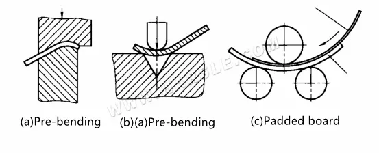
Eliminação da seção reta de curvatura
A Figura (c) mostra que o método de adicionar uma almofada para eliminar a seção reta da laminação é colocar uma almofada nos dois rolos inferiores (para reduzir a pressão da cama de laminação, a almofada pode ser laminada com antecedência), e a espessura da almofada é curva. O blank é mais espesso, é melhor ter cerca de duas vezes a espessura, e o comprimento é ligeiramente maior do que o blank dobrado. Durante a laminação, o blank é colocado sobre a placa de apoio, e a placa de apoio é usada para excluir seções retas. Para peças com grande curvatura, a seção reta deve ser eliminada antes da laminação. Se eliminada após a laminação, a curvatura da peça já for grande, e a placa de apoio for adicionada, é provável que seja bloqueada pela viga e não possa ser laminada. Para peças com pequena curvatura, a seção reta pode ser eliminada pelo método da placa de apoio antes ou depois da laminação.
4. Ao laminar, como o rolo exerce certa pressão sobre a chapa e atrito com a superfície da chapa, ao laminar peças com altos requisitos de qualidade de superfície, a superfície do rolo e da chapa deve ser limpa antes da laminagem. Para chapas com fita adesiva e outras superfícies protetoras, preste atenção também à remoção de resíduos de metal e cola na superfície do papel, e rasgue a parte sobreposta da fita adesiva, caso contrário, a qualidade da superfície das peças será afetada.
5. O processo de laminação por laminação não é usado apenas para chapas metálicas, mas também para perfis. A maior diferença entre laminação de perfis e laminação de chapas é que, na laminação de perfis, os rolos precisam ser projetados e fabricados de acordo com o formato da seção transversal do perfil, e os rolos são montados sobre os rolos. A laminação é realizada pelo rolo, portanto, toda vez que a mesma peça é laminada, é necessário substituir o rolo secundário. No processo de laminação e dobra, o perfil está sujeito a deformações, como distorção e torção da forma da seção transversal, e a quantidade de reparos subsequentes é grande. Portanto, é geralmente usado na produção em pequena escala ou na conclusão de processos auxiliares. Na produção em lote, além de peças simples ou de baixa demanda formadas por laminação por laminação, a maioria das peças pequenas é formada por dobra por prensa, e as peças grandes são formadas por dobra por estiramento.
Dobramento de laminação a quente
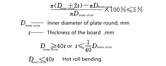
A chapa de aço pode ser laminada à temperatura ambiente ou após aquecimento. Acredita-se geralmente que, quando o aço carbono é laminado a frio, sua deformação plástica não deve exceder 5%, ou seja, a razão entre a diferença entre a circunferência externa e a circunferência interna da chapa arredondada e a circunferência interna não deve exceder 5%. Pode ser expressa como
A laminação a quente consiste na dobra e conformação do material a ser processado após o aquecimento. À medida que a temperatura de aquecimento aumenta, a resistência à deformação do material metálico diminui e a plasticidade aumenta. Portanto, é benéfica para o processamento de materiais metálicos difíceis de deformar e fabricar à temperatura ambiente, além de melhorar o escopo de utilização do equipamento. Na produção e no processamento, quando a capacidade de processamento da laminadora é insuficiente ou o grau de deformação do material processado é muito grande, a laminação a quente pode ser utilizada.
1. A temperatura de aquecimento da dobra por laminação a quente é mostrada na tabela para a temperatura de aquecimento da dobra por laminação a quente de materiais comumente usados.
| Designação do material | Temperatura de flexão térmica/°C | |
| aquecimento | rescisão | |
| Q235A, 15, 20 | 900-1050 | ≥700 |
| 15g, 20g, 22g | 900-1050 | ≥700 |
| 16Mn(R)、15MnV(R) | 900-1050 | ≥750 |
| 18MnMoNb, 15MnVN | 900-1050 | ≥750 |
| OCr13, 1Cr13 | 1000-1100 | ≥850 |
| 1Cr18Ni9Ti, 12Cr1MoV | 950-1100 | ≥850 |
| H62, H68 | 600-700 | ≥400 |
| 1060(L2)、5AO2(LF2)、3A21(LF21) | 350-450 | ≥250 |
| titânio | 420-560 | ≥350 |
| Liga de titânio | 600-840 | ≥500 |
2. Precauções para dobra a quente: Embora o princípio básico da dobra a quente seja o mesmo da dobra a frio, o material metálico da dobra a quente é aquecido. Portanto, atenção especial deve ser dada aos seguintes pontos durante a operação de dobra a quente.
●A dobra a quente não precisa considerar a ocorrência de retorno elástico de flexão, mas os fenômenos de afinamento, alongamento e indentação durante a dobra a quente são mais pronunciados do que na dobra a frio. Portanto, deve-se prestar total atenção ao projeto do processo de aquecimento e ao processo de dobra a quente.
● Devido à diferença de temperatura entre a superfície metálica e o interior durante o aquecimento, o grau de expansão interna e externa do material metálico é desigual, resultando em tensões térmicas. Durante o processo de aquecimento, o tempo de transformação da estrutura metalográfica também é diferente. A transformação da estrutura ocorre primeiro e, em seguida, causa tensões entre as estruturas. Portanto, para materiais com seções mais espessas, a temperatura do forno deve ser evitada, pois não deve ser muito alta ao entrar no forno. Como resultado, a velocidade de aquecimento do tarugo é muito rápida e a expansão térmica é muito grande para produzir trincas por tensão; para materiais que requerem recozimento ou têmpera + revenimento e outros tratamentos térmicos, eles devem ser realizados separadamente após a laminação a quente.
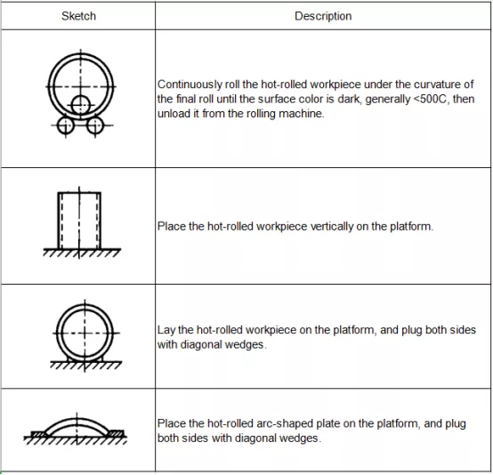
● Para a dobra de um cilindro fechado, role-o até a solda recém-fechada. No entanto, para evitar que a seção simples seja descarregada prematuramente devido à alta temperatura e deformada devido ao seu peso, é necessário continuar laminando na máquina de dobra para resfriamento. Quando a curvatura da seção simples laminada atender aos requisitos, a pressão descendente do rolo superior sobre a seção simples deve ser liberada a tempo de permitir que a seção simples passe sobre a máquina de enrolamento para evitar que o afinamento da bobina quente continue a ocorrer. De acordo com o desempenho de endurecimento do material, medidas apropriadas de resfriamento forçado podem ser tomadas, como sopro de ar, para acelerar a taxa de resfriamento. Durante esta etapa da laminação, o princípio de manter o raio de curvatura da seção do tubo estável é o princípio, e a seção do tubo só pode ser removida quando a temperatura da seção do tubo cair a ponto de ser difícil ver a cor vermelha quente (<500 °C) na superfície. O posicionamento da seção do tubo descarregada também deve prestar atenção à nova deformação devido ao seu peso. Após a dobra a quente, o método de posicionamento razoável da peça de trabalho é mostrado na tabela.
Greece-Customer-Feedback.jpg)