


Correct ESTUN E315P Axis Parameters are essential for reliable servo-axis movement during press brake commissioning. The E315P controls machine-axis movement through servo drives, so the controller parameters must correspond with the servo system, physical motor direction, encoder counting direction, and actual machine movement.
The commissioning guide uses the X-axis as an example to explain the complete setup process. This includes preparing the servo drive, entering the X-axis parameter interface, configuring communication and axis parameters, performing axis teaching, adjusting positioning performance, and verifying the movement direction in Manual Mode.
This guide explains how to complete these settings systematically before putting the machine into normal operation.
Prepare the Servo Drive Before Axis Setup
Before configuring ESTUN E315P Eixo Parameters, the servo drive must be prepared correctly.
Machine-axis movement depends on motors controlled by servo drives. Therefore, the servo drive parameters should first be configured according to the actual machine configuration.
According to the commissioning guide, the E315P exclusively supports ED3L drives. Detailed communication settings should be completed according to the relevant communication instructions in Appendix B of the manual.
Servo-drive preparation should be completed before detailed axis parameter adjustment. Otherwise, incorrect communication settings may prevent the controller and servo system from working together properly.
Enter the ESTUN E315P Axis Parameters Interface
The manual uses the X-axis as the example for servo parameter configuration. The same setup concept can then be applied according to the requirements of the corresponding machine axis.
To access the X-axis settings:
- Abra o System Settings interface.
- Digitar Machine Parameters using Level 1 permission.
- Selecione X-Axis Parameters.
The interface contains the parameters required to establish communication, define axis behavior, and prepare the X-axis for teaching and movement.
Before making changes, make sure the settings correspond with the servo drive and actual machine configuration.
Configure the X-Axis Servo Parameters
The first step in configuring ESTUN E315P Axis Parameters is to set the basic servo-related parameters.
Defina o Servo Type e Servo Node ID for the X-axis according to the connected servo system.
Em seguida, defina o Logical Axis Number.
These settings establish the relationship between the controller and the servo axis. After completing them, cycle power to the control unit.
This power cycle is an important part of the procedure because it allows the controller to establish proper communication with the servo system using the updated settings.
Do not continue directly to axis teaching without completing the required power cycle.
Set the Multiplier and Divider Factors
After restarting the controller, return to:
Machine Parameters → X-Axis Parameters
Then set the Multiplier Factor e Divider Factor.
These ESTUN E315P Axis Parameters form part of the X-axis configuration and should correspond with the previously configured drive parameters.
Because incorrect values can affect axis positioning, they should not be entered arbitrarily. The configuration should be based on the actual servo and machine setup.
Once these factors have been confirmed, the axis can proceed to the teaching stage.
Enable X-Axis Teaching
Within the X-axis parameter interface, set X-Axis Teach Enable para Habilitar.
Then return to:
Programming Constants → Teaching Parameters
From this interface, perform the X-axis teaching operation.
Teaching allows the E315P control unit to record the current X-axis position value. This establishes the position information required for precise motion control.
For this reason, teaching is not simply an optional adjustment after servo configuration. It forms an important part of establishing the relationship between the controller’s position information and the actual mechanical position of the axis.
Complete the X-Axis Teaching Operation
After entering Teaching Parameters, perform the teaching procedure for the X-axis according to the actual machine position.
The purpose is to ensure that the position recognized by the controller corresponds with the physical position of the backgauge axis.
Once the teaching process has been completed, the controller has the necessary reference information for subsequent X-axis positioning.
If the mechanical position and controller position do not correspond correctly, the axis may not move to the expected location even when the servo communication itself is functioning normally.
Therefore, position teaching should be confirmed before evaluating final positioning performance.
Adjust Positioning Speed and Acceleration
After teaching, configure the motion-related ESTUN E315P Axis Parameters according to the actual machine condition.
The commissioning guide specifically identifies:
- X-Axis Positioning Speed
- X-Axis Acceleration/Deceleration Time
These parameters affect how the X-axis moves during positioning.
The values should be selected according to the actual machine and servo conditions rather than adjusted without reference to the mechanical system.
At this stage, the basic servo communication, position relationship, and motion parameters have been established. The next important task is verifying whether the physical axis moves in the correct direction.
How to Adjust the Axis Motion Direction
Motor installation can affect the actual orientation of axis movement. Therefore, the direction cannot be determined only from the physical motor installation.
The E315P uses two related settings:
Motor Rotation
- CW — Clockwise
- CCW — Counterclockwise
Encoder Counting
- Aumentar
- Decrease
Before configuring the X-axis, the actual motor rotation should be identified. The Motor Rotation and Encoder Counting settings are then combined to achieve the required axis movement direction.
This relationship is important because the commanded movement, actual mechanical movement, and encoder counting direction must correspond correctly.
Verify Axis Movement in Manual Mode
After configuring the movement direction, use Manual Mode to verify whether the ESTUN E315P Axis Parameters produce the expected machine movement.
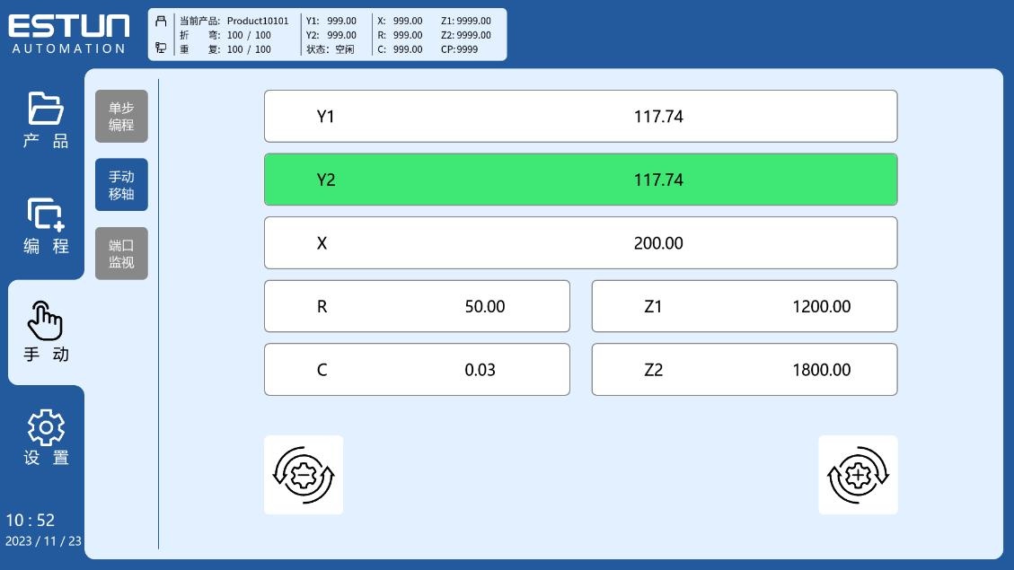
The commissioning guide provides a straightforward verification procedure:
- Acesse o Modo manual interface.
- Select the target axis and a movement direction.
- Execute the movement command.
- Observe the physical axis movement.
- Compare the actual movement with the commanded direction.
This check should be performed carefully because it verifies the relationship between the parameter configuration and the actual machine response.
If the physical axis moves differently from the command, the direction-related parameters require further adjustment.
Understand the Axis Direction Calibration Targets
The commissioning guide provides a Servo Axis Direction Calibration Matrix for the Y, X, and R axes.
The required movement and encoder-counting relationships are:
| Servo Axis | Physical Motion | Encoder Counting |
|---|---|---|
| E | Downward | Aumentar |
| X | Backward | Aumentar |
| R | Upward | Aumentar |
| E | Upward | Decrease |
| X | Forward | Decrease |
| R | Downward | Decrease |
For the X-axis, for example, backward movement corresponds to Increase, while forward movement corresponds to Decrease.
For the Y-axis, downward movement corresponds to Increase and upward movement corresponds to Decrease.
For the R-axis, upward movement corresponds to Increase and downward movement corresponds to Decrease.
These relationships provide calibration targets when verifying the actual axis movement.
What If the Axis Direction Is Incorrect?
If the actual machine-axis movement or encoder counting direction conflicts with the command, the commissioning guide identifies two parameters that should be checked and modified:
- Motor Rotation
- Encoder Counting
Do not judge the result only by whether the motor itself rotates clockwise or counterclockwise. The final objective is to obtain the required physical axis movement and encoder counting relationship.
The calibration matrix defines the required outcome, while the Increase and Decrease options in the controller interface are functional parameter labels.
This distinction is important when commissioning ESTUN E315P Axis Parameters, because the physical movement of the machine axis is the final reference for verification.
Final Check After Axis Parameter Setup
After configuring the servo settings, teaching the position, adjusting the motion parameters, and verifying the movement direction, perform another Manual Mode test.
Confirm that the selected axis moves in the commanded physical direction and that the encoder counting behavior agrees with the calibration target.
If either result is incorrect, review the Motor Rotation and Encoder Counting settings before proceeding with further commissioning.
A systematic setup sequence—servo configuration, communication confirmation, axis teaching, motion adjustment, and direction verification—helps ensure that the ESTUN E315P Axis Parameters correspond correctly with the actual press brake servo system.
Perguntas frequentes (FAQ)
Why Is a Power Cycle Required After Setting the Servo Parameters?
After configuring the Servo Type, Servo Node ID, and related axis settings, the control unit should be power-cycled so that the updated configuration can be applied and proper communication with the servo system can be established. Complete this step before continuing with teaching and motion verification.
Can I Copy X-Axis Parameters Directly to Another Axis?
No. The manual uses the X-axis as an example to demonstrate the configuration process, but each servo axis has its own mechanical function and movement requirements. Parameters should be configured according to the actual axis and machine setup rather than copied directly.
What Should I Do Before Moving to Datum Setup?
Before continuing to Datum configuration, confirm that the servo system communicates normally, the axis has been taught correctly, and Manual Mode commands produce the expected physical movement and encoder counting direction. Any direction or position-related problem should be corrected first.
Conclusão
Correct ESTUN E315P Axis Parameters establish the relationship between the controller, servo drive, encoder feedback, and actual machine-axis movement. The setup process begins with servo configuration and communication settings, followed by multiplier and divider factors, axis teaching, positioning speed, and acceleration/deceleration settings.
After these parameters are configured, Manual Mode should be used to verify actual axis movement. The Motor Rotation and Encoder Counting parameters must work together so that the physical movement matches the required calibration target.
By completing each stage in sequence and verifying the actual machine response, technicians can establish reliable servo-axis control before proceeding to Datum setup and further E315P commissioning procedures.


