


Análise de falhas do sistema hidráulico da máquina de laminação de chapas

Na minha experiência trabalhando com placa máquinas de laminação, Tenho enfrentado vários desafios, principalmente no que diz respeito sistema hidráulico Falha. O sistema hidráulico é crucial para a operação da máquina, e qualquer falha pode levar a paradas significativas e reparos dispendiosos. Compreender as causas e implicações das falhas do sistema hidráulico é essencial para manter a eficiência e a produtividade nos processos de fabricação. Neste artigo, compartilharei insights da minha análise de falhas do sistema hidráulico, discutindo problemas comuns, medidas preventivas e soluções para garantir o desempenho ideal em operações de laminação de chapas.
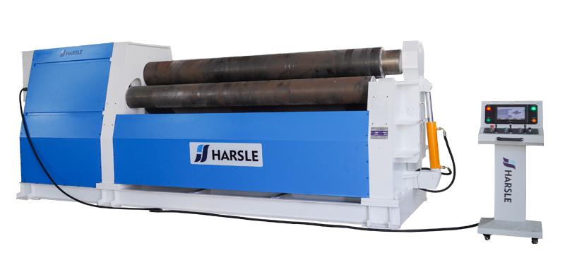
A máquina de laminação de chapas é um equipamento de conformação de uso geral que dobra e lamina chapas de metal em cilindros, cones, superfícies curvas ou outros formatos, e é amplamente utilizada em petróleo, produtos químicos, fabricação de máquinas e outros campos.
Princípio de funcionamento do sistema hidráulico
O Máquina de laminação de placas de três rolos com ajuste simétrico para cima 40 × 4000 Projetado para dobrar chapas de aço com espessuras que variam de 16 mm a 40 mm à temperatura ambiente, o equipamento consiste em vários componentes principais, incluindo o mecanismo de transmissão principal, o mecanismo de elevação do rolo superior, os mancais de suporte e móveis, o dispositivo de prensagem, o dispositivo de frenagem e outros sistemas de suporte. A máquina opera com base no princípio de três rolos que aplicam pressão à chapa de aço, o que faz com que o material se dobre e assuma o formato cilíndrico desejado. Isso a torna altamente eficiente na fabricação de componentes laminados grandes e precisos.
Durante a operação, a peça cilíndrica laminada pode ser facilmente removida da extremidade invertida da máquina. O processo envolve a inclinação do mancal móvel na extremidade de descarga, afastando-o do rolo superior. Ao mesmo tempo, um bloco de pressão do cilindro hidráulico instalado na extremidade superior do rolo pressiona para baixo, criando uma leve inclinação para cima no lado de descarga do rolo superior. Esse ajuste controlado garante que a peça acabada possa ser liberada e descarregada suavemente, sem deformação. Esse mecanismo aumenta a confiabilidade, melhora a produtividade e garante um desempenho estável para operações contínuas de conformação de metais.
O sistema hidráulico da laminadora de três rolos (Figura 1) possui dois cilindros de óleo, A e B, controlados por duas válvulas direcionais eletromagnéticas. O cilindro A controla a elevação do suporte móvel, enquanto o cilindro B levanta e pressiona o rolo superior para que o descarregamento ocorra sem problemas.

Figura 1——Circuito de óleo do sistema hidráulico
A sequência de operação do sistema hidráulico começa com a pressão do botão iniciar, que aciona o motor e aciona a bomba hidráulica. Quando as três válvulas direcionais eletromagnéticas são colocadas em suas posições intermediárias, o sistema entra em um estado de alívio de pressão. Este projeto reduz efetivamente o consumo de energia, pois o sistema hidráulico não mantém a pressão continuamente quando nenhuma ação específica é necessária. Esta etapa inicial garante a eficiência energética e protege os componentes do sistema contra desgaste desnecessário, criando uma base estável para as próximas operações da máquina.
Em seguida, o operador pressiona válvula solenóide 6 e válvula solenóide 4 na extremidade de baixa pressão. Esta ação ativa cilindro A, fazendo com que o suporte móvel desça de forma constante. À medida que o cilindro A abaixa o suporte para aproximadamente 85 graus, ele encontra o interruptor de limite de curso. Neste momento, válvula solenóide 9 e válvula solenóide 4 (revertendo para a extremidade de alta pressão) são acionados, o que ativa cilindro B. O cilindro B pressiona então a extremidade traseira do rolo superior. Assim que o rolo inclina para cerca de 3 graus, atinge o fim de curso, a operação para e a peça de trabalho é descarregada com sucesso.
Após a conclusão do descarregamento, o processo continua pressionando o botão botão de resposta. Este comando faz com que cilindro B para retrair, restaurando o rolo superior à posição horizontal, confirmada pelo fim de curso. Em seguida, cilindro A move o suporte para cima, guiando-o de volta à sua posição original e alinhando-o precisamente com o luva do cone do rolo superior. Nesta fase, toda a sequência hidráulica foi concluída. O sistema está agora reiniciado, totalmente estável e preparado para o próximo ciclo de operação, garantindo eficiência e confiabilidade.
Análise e tratamento de falhas do sistema hidráulico
Durante o uso único deste sistema hidráulico, o cilindro A parece conseguir subir, mas às vezes não consegue subir, e não consegue parar em nenhuma posição, caindo automaticamente, e o cilindro B se move ocasionalmente. O sistema hidráulico geral é composto por elementos filtrantes, tubulações e diversas bombas e válvulas. A bomba hidráulica fornece pressão, e a válvula de alívio evita que a pressão do sistema fique muito alta, permitindo a descarga a tempo.
A válvula reversora controla a expansão e a contração do cilindro hidráulico, controlando a direção do fluxo de óleo do cilindro hidráulico. A válvula borboleta controla a velocidade do óleo do cilindro hidráulico. Os componentes hidráulicos envolvidos no sistema hidráulico incluem uma bomba hidráulica, uma válvula de alívio, uma válvula direcional de três posições e quatro vias, uma válvula borboleta unidirecional, uma válvula unidirecional controlada hidraulicamente, um cilindro hidráulico e outros acessórios.
O válvula de retenção de controle hidráulico é uma válvula especializada que permite a circulação reversa do fluido quando controlada por pressão. Ao contrário de uma válvula de retenção padrão, ela é equipada com um circuito de óleo de controle adicional. Quando este circuito de controle não é alimentado com óleo sob pressão, a válvula funciona como uma válvula de retenção normal — o fluido só pode fluir da entrada para a saída, impedindo o fluxo reverso. No entanto, quando o circuito de óleo de controle é pressurizado, a haste do pistão é empurrada pela pressão, abrindo a válvula e conectando a entrada e a saída. Nessa condição, o fluxo reverso torna-se possível.
As falhas do sistema hidráulico são analisadas da seguinte forma:
(1) Analise o cilindro B. Na ausência de pressão, foram considerados os problemas de válvulas de alívio, bombas e vedações do cilindro.
① Verifique o carretel da válvula de alívio, pois há vestígios de arranhões. Portanto, a nova válvula de alívio foi substituída, mas o defeito não foi corrigido.
2. Teste a qualidade da bomba. Tampe a extremidade do cabeçote do cilindro B, a pressão pode atingir a escala completa, indicando que a bomba de engrenagens não apresenta falhas.
3. Remova o cilindro B. Após a remoção do cilindro B, constatou-se que a vedação da haste do pistão estava completamente rompida. Após a substituição da nova vedação, o cilindro B funcionou normalmente.
(2) Análise do cilindro A. Considere a válvula de retenção de controle hidráulico e a vedação do cilindro A.
① Verifique a válvula de retenção do controle hidráulico; o núcleo da válvula apresenta falhas. Após a retificação, a válvula de retenção do controle hidráulico foi reinstalada, mas o cilindro A ainda não pôde ser levantado e a falha não foi eliminada.
2. Desmonte a junta do tubo frontal da válvula de retenção de controle hidráulico e verifique se não há fluxo de óleo hidráulico. Em condições de funcionamento, pressione o carretel da válvula direcional eletromagnética com uma chave de fenda e o óleo hidráulico flui pela cabeça do tubo, indicando que a válvula direcional eletromagnética 6 está com defeito. Após a substituição da nova válvula, o cilindro A pode funcionar, mas ainda pode não estar parcialmente vedado.
③ Substitua a vedação do cilindro A, o sistema hidráulico está normal.
Conclusão
Com o aprimoramento contínuo da integração eletromecânica e da automação de equipamentos, os acionamentos hidráulicos contam com as vantagens de estrutura simples, tamanho compacto, alta potência de saída, regulagem de velocidade contínua, comutação frequente e automação fáceis de implementar. São amplamente utilizados em máquinas, na indústria aeronáutica e em outros setores. Portanto, engenheiros e técnicos devem dominar o desempenho dos componentes hidráulicos e aprender a analisar e eliminar as falhas do sistema hidráulico para melhor atender às necessidades da empresa.


