Introdução à prensa hidráulica de forjamento isotérmico

As an industry expert in hydraulic machinery, I am excited to share insights into the introduction of isothermal forging prensas hidráulicas. These innovative machines play a crucial role in the forging process, allowing for enhanced material properties and reduced energy consumption. In this article, I will explore the fundamental principles of isothermal forging, the advantages of using hydraulic presses in this application, and how they can improve manufacturing efficiency. By understanding the features and benefits of isothermal forging hydraulic presses, we can better appreciate their impact on modern metalworking practices.
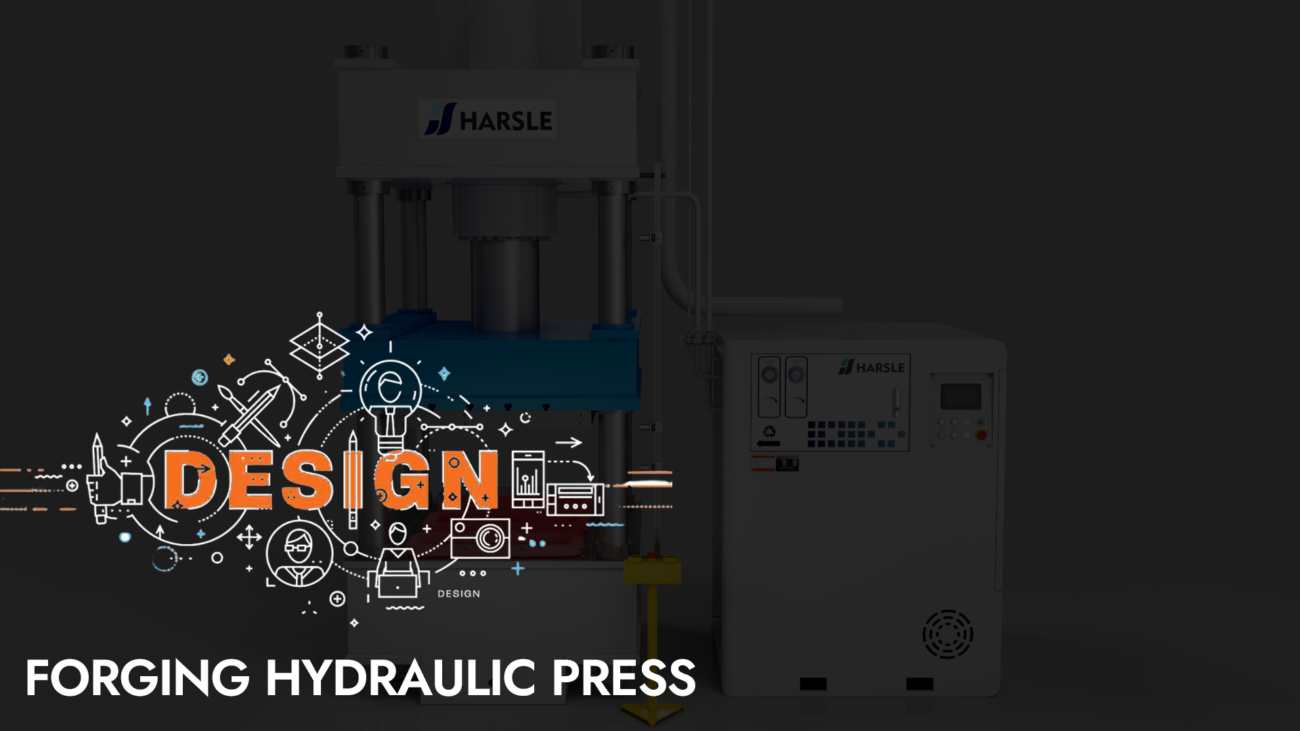
This article introduces a hydraulic machine specially used for isothermal forging. The shape of the equipment is shown in Figure 1. The hydraulic machine has high precision, anti-eccentric load capacity, and a sliding table structure designed to deal with large draft forces.
Introduction to Isothermal Forging Hydraulic Press

The isothermal forging hydraulic press described in this article is as follows: the heating furnace (including the mold) is installed on the worktable of the device together, and the upper mold is connected with the slider to be fixed. First, the mold is heated, the process generally takes 7-8 hours. After that, the forging blank is placed in the mold and heated to a predetermined temperature, and the equipment starts to press-form the blank. During this process, the mold and the blank are kept at the forming temperature. Finally, the equipment is kept under pressure until the workpiece and mold are cooled to room temperature, and the press slider returns to take out the finished parts. Therefore, this equipment requires a long holding time for the hydraulic press and high-pressure stability requirements.
The key technology of isothermal forging hydraulic press
The fuselage adopts a split pre-tensioned frame structure, which is composed of upper beam, lower beam, left and right uprights, four tie rods, and tensile nuts, etc. The upper beam, lower beam, and left and right uprights are pre-stressed by hydraulic overpressure through the tie rods. The beams are connected by positioning keys. The upper beam, the lower beam, and the four columns are welded with steel plates and have sufficient rigidity and strength.
The slider guide adopts inclined wedge type 45-degree X-shaped guide rail, which is easy to adjust and has high adjustment accuracy, which can effectively prevent the influence of thermal deformation on the running accuracy of the slider and has a strong anti-eccentric load capacity. In order to enhance the anti-eccentric load capacity of the slider and improve the running accuracy of the slider, the guide length of the slider is increased to 2.5 times that of the conventional press.


To facilitate mold replacement, the equipment is equipped with a mobile worktable as shown in Figure 3, when the mold is replaced, the worktable is moved out of the fuselage to facilitate the lifting of the mold. Due to the release force of isothermal forging parts reaching about 4000kN, the conventional mobile table clamping device cannot meet its clamping requirements. The mobile table will be brought up during demolding, resulting in the situation that the parts cannot be taken out. Therefore, this machine has specially designed the mobile station drive and anti-banding scheme as shown in Figure 4.
To prevent the mobile table from being brought up by the demoulding force, two brackets are provided on the two uprights of the equipment and the left and right uprights are welded together, and the distance between the lower plane of the bracket and the lower plane of the upright is controlled by the precision of dimensional tolerances. When the mobile platform moves into the press, there is a small gap (0.2~0.3mm) between its upper plane and the lower plane of the column support. When the slider returns and the cylinder is ejected, the demoulding force will drive the mobile table and the lower die to rise, and cannot move up under the restriction of the column bracket. The demoulding force is borne by the column bracket. With this anti-banding structure, the gap between the mobile station and the column bracket is small. Conventional roller-type mobile stations require a lifting clearance of 10 to 15 mm to prevent damage to the device due to the force of the roller when the device is working.
According to the working conditions of the isothermal forging prensas hidráulicas equipment, the mobile platform of the equipment adopts sliding type, and the mobile platform slides on the guide rail and the upper surface of the lower beam. Since the sliding friction force is greater than the rolling friction force, the driving force of the mobile table needs to be very large, and the mobile table is driven by a piston-cylinder with a large thrust. To ensure that the moving speed of the mobile station is stable and controllable, and the moving-in and moving-out speeds are consistent, a controllable differential circuit is used to control the driving cylinder as shown in FIG. 5. When the piston rod is pushed out, the solenoid valve Y2 must not be powered, and a differential circuit is formed between the rod cavity and the rodless cavity, and the oil in the rod cavity enters the rodless cavity to increase the ejection speed. Conversely, when the piston rod is retracted, the solenoid valve Y2 must electrically cut off the differential circuit between the rod chamber and the rodless chamber. In this way, under the same input flow rate, the pushing and returning speed of the cylinder is the same.

In the isothermal forging control system, the main oil pump uses a digital pump and the control loop uses a high-frequency response proportional servo valve. When the speed is low, the PLC controls the opening of the high-frequency response proportional servo valve to achieve a stable output of small flow. To ensure the smooth operation of the slider at a low speed, a specially set small oil pump is used to input a certain pressure to the lower chamber of the master cylinder piston cylinder, so that the slider operates under a large back pressure, thereby preventing the occurrence of crawling. The isothermal forging control system can realize constant speed control within the working speed range of 0.02~1mm/s. Due to the long pressure holding time of the equipment, the oil flow required by the hydraulic system is very small at this time, and only certain pressure stability needs to be maintained. When the digital pump is used to maintain the pressure of the equipment, the displacement of the digital pump is adjusted to the minimum level that can maintain constant pressure through the PLC program control.
The electrical system is equipped with a computer for industrial control, and the technological actions and parameters of the press can be set by the computer to realize automatic control of the entire working process.
At the same time, it can record, store, and print various working parameters, including the following aspects:
⑴The position-time curve and data of the four points of the slider;
⑵Average position of slider-time curve and data;
⑶ pressure-time curve and data of the master cylinder;
⑷Speed-time curve and data of the slider.
To achieve controllability and traceability of the entire production process.
Russia-Customer-Feedback-5.jpg)
Russia-Customer-Feedback-4.jpg)
Russia-Customer-Feedback.jpg)