Views: 3686 Author: Site Editor Publish Time: 2024-03-11 Origin: Site


The bending machine belongs to a kind of forging Machinery.It is a major role in the metal processing industry. Products are widely applied to: light industry, aviation, shipping, metallurgy, instruments, electrical appliances, stainless steel products, steel structure construction and decoration industries.
Hydraulic system uses piston pump of pressure compensation to supply oil, the oil return throttle control, rational use of energy. Vertical hydraulic cylinder uses balance and locking measures, so it works safely and reliablely. At the same time hydraulic cylinders as the implementation of components haves great clamping force and shear force . When system shear plate material ,its performance is good.
The design of the press systems, sheet metal shear system and hydraulic pump stations system have the circuit design and structure of the pumping station, layout and some non-standard components design. In the design process , it achieves structure compact and layout rational and manufacture simple.
Any media (liquid or gas) that flows naturally or can be forced to flow could be used to transmit energy in a fluid power system. The earliest fluid used was water hence the name hydraulics was applied to systems using liquids. In modern terminology, hydraulics implies a circuit using mineral oil. Figure 1-1 shows a basic power unit for a hydraulic system.(Note that water is making something of a comeback in the late '90s; and some fluid power systems today even operate on seawater.) The other common fluid in fluid power circuits is compressed air. As indicated in Figure 1-2, atmospheric air -- compressed 7 to 10 times -- is readily available and flows easily through pipes, tubes, or hoses to transmit energy to do work. Other gasses, such as nitrogen or argon, could be used but they are expensive to produce and process.
Power is least understood by industry in general. In most plants there are few persons with direct responsibility for fluid power circuit design or maintenance. Often, general mechanics maintain fluid power circuits that originally were designed by a fluid-power-distributor salesperson. In most facilities, the responsibility for fluid power systems is part of the mechanical engineers' job description. The problem is that mechanical engineers normally receive little if any fluid power training at college, so they are ill equipped to carry out this duty. With a modest amount of fluid power training and more than enough work to handle, the engineer often depends on a fluid power distributor's expertise.
To get an order, the distributor salesperson is happy to design the circuit and often assists in installation and startup. This arrangement works reasonably well, but as other technologies advance, fluid power is being turned down on many machine functions. There is always a tendency to use the equipment most understood by those involved.
Fluid power cylinders and motors are compact and have high energy potential. They fit in small spaces and do not clutter the machine. These devices can be stalled for extended time periods, are instantly reversible, have infinitely variable speed, and often replace mechanical linkages at a much lower cost. With good circuit design, the power source, valves, and actuators will run with little maintenance for extended times. The main disadvantages are lack of understanding of the equipment and poor circuit design, which can result in overheating and leaks. Overheating occurs when the machine uses less energy than the power unit provides. (Overheating usually is easy to design out of a circuit.) Controlling leaks is a matter of using straight-thread O-ring fittings to make tubing connections or hose and SAE flange fittings with larger pipe sizes. Designing the circuit for minimal shock and cool operation also reduces leaks.
A general rule to use in choosing between hydraulics or pneumatics for cylinders is: if the specified force requires an air cylinder bore of 4 or 5 in. or larger, choose hydraulics. Most pneumatic circuits are under 3 hp because the efficiency of air compression is low. A system that requires 10 hp for hydraulics would use approximately 30 to 50 air-compressor horsepower. Air circuits are less expensive to build because a separate prime mover is not required, but operating costs are much higher and can quickly offset low component expenses. Situations where a 20-in. bore air cylinder could be economical would be if it cycled only a few times a day or was used to hold tension and never cycled.
Both air and hydraulic circuits are capable of operating in hazardous areas when used with air logic controls or explosion-proof electric controls. With certain precautions, cylinders and motors of both types can operate in high-humidity atmospheres . . . or even under water.
When using fluid power around food or medical supplies, it is best to pipe the air exhausts outside the clean area and to use a vegetable-based fluid for hydraulic circuits.
Some applications need the rigidity of liquids so it might seem necessary to use hydraulics inthese cases even with low power needs. For these systems, use a combination of air for the
Power source and oil as the working fluid to cut cost and still have lunge-free control with options for accurate stopping and holding as well. Air-oil tank systems, tandem cylinder systems, cylinders with integral controls, and intensifiers are a few of the available components.
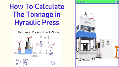
The reason fluids can transmit energy when contained is best stated by a man from the 17th century named Blaise Pascal. Pascal's Law is one of the basic laws of fluid power. This law says: Pressure in a confined body of fluid acts equally in all directions and at right angles to the containing surfaces. Another way of saying this is: If I poke a hole in a pressurized container or line, I will get PSO. PSO stands for pressure squirting out and puncturing a pressurized liquid line will get you wet. Figure 1-3 shows how this law works in a cylinder application. Oil from a pump flows into a cylinder that is lifting a load. The resistance of the load causes pressure to build inside the cylinder until the load starts moving. While the load is in motion,pressure in the entire circuit stays nearly constant. The pressurized oil is trying to get out of the pump, pipe, and cylinder, but these mechanisms are strong enough to contain the fluid.When pressure against the piston area becomes high enough to overcome the load resistance,the oil forces the load to move upward. Understanding Pascal's Law makes it easy to see how all hydraulic and pneumatic circuits function.
Notice two important things in this example. First, the pump did not make pressure; it only produced flow. Pumps never make pressure. They only give flow. Resistance to pump flow causes pressure. This is one of the basic principles of fluid power that is of prime importance to troubleshooting hydraulic circuits. Suppose a machine with the pump running shows almost 0 psi on its pressure gauge. Does this mean the pump is bad? Without a flow meter at the pump outlet, mechanics might change the pump, because many of them think pumps make pressure. The problem with this circuit could simply be an open valve that allows all pump flow to go directly to tank. Because the pump outlet flow sees no resistance, a pressure gauge shows little or no pressure. With a flow meter installed, it would be obvious that the pump was all right and other causes such as an open path to tank must be found and corrected.
Another area that shows the effect of Pascal's law is a comparison of hydraulic and mechanical leverage. Figure 1-4 shows how both of these systems work. In either case, a large force is offset by a much smaller force due to the difference in lever-arm length or piston area.Notice that hydraulic leverage is not restricted to a certain distance, height, or physical location like mechanical leverage is. This is a decided advantage for many mechanisms because most designs using fluid power take less space and are not restricted by position considerations. A cylinder, rotary actuator, or fluid motor with almost limitless force or torque can directly push or rotate the machine member. These actions only require flow lines to and from the actuator and feedback devices to indicate position. The main advantage of linkage actuation is precision positioning and the ability to control without feedback.
At first look, it may appear that mechanical or hydraulic leverage is capable of saving energy.For example: 40,000 lb is held in place by 10,000 lb in Figure 1-4. However, notice that the ratio of the lever arms and the piston areas is 4:1. This means by adding extra force say to the 10,000-lb side, it lowers and the 40,000-lb side rises. When the 10,000-lb weight moves down a distance of 10 in., the 40,000-lb weight only moves up 2.5 in.
Work is the measure of a force traversing through a distance. (Work = Force X Distance.).Work usually is expressed in foot-pounds and, as the formula states, it is the product of force in pounds times distance in feet. When a cylinder lifts a 20,000-lb load a distance of 10 ft, the cylinder performs 200,000 ft-lb of work. This action could happen in three seconds, three minutes, or three hours without changing the amount of work.
When work is done in a certain time, it is called power. {Power = (Force X Distance) / Time.}A common measure of power is horsepower - a term taken from early days when most persons could relate to a horse's strength. This allowed the average person to evaluate to new means of power, such as the steam engine. Power is the rate of doing work. One horsepower is defined as the weight in pounds (force) a horse could lift one foot (distance) in one second (time). For the average horse this turned out to be 550 lbs. one foot in one second. Changing the time to 60 seconds (one minute), it is normally stated as 33,000 ft-lb per minute.
No consideration for compressibility is necessary in most hydraulic circuits because oil can only be compressed a very small amount. Normally, liquids are considered to be incompressible, but almost all hydraulic systems have some air trapped in them. The air bubbles are so small even persons with good eyesight cannot see them, but these bubbles allow for compressibility of approximately 0.5% per 1000 psi.
Applications where this small amount of compressibility does have an adverse effect include: single-stroke air-oil intensifiers; systems that operate at very high cycle rates; servo systems that maintain closetolerance positioning or pressures; and circuits that contain large volumes of fluid. In this book, when presenting circuits where compressibility is a factor, it will be pointed out along with ways to reduce or allow for it.
Another situation that makes it appear there is more compressibility than stated previously is if pipes, hoses, and cylinder tubes expand when pressurized. This requires more fluid volume to build pressure and perform the desired work.
In addition, when cylinders push against a load, the machine members resisting this force may stretch, again making it necessary for more fluid to enter the cylinder before the cycle can finish.
As anyone knows, gasses are very compressible. Some applications use this feature. In most fluid power circuits, compressibility is not advantageous; in many, it is a disadvantage. This means it is best to eliminate any trapped air in a hydraulic circuit to allow faster cycle times and to make the system more rigid.

 English
 Pусский