


دليل حساب بدل الانحناء لمكابح الضغط

يعد حساب تخطيط النمط المسطح الصحيح أمرًا بالغ الأهمية للحصول على جزء نهائي عالي الجودة من مكابح الضغطومع ذلك، لا يعرف العديد من مبرمجي CAD وCNC كيفية حساب القيم المطلوبة. قبل سنوات، كان الخبراء الحقيقيون يصممون أوراقًا توضيحية ويلصقونها على الحائط. كانوا يعلّمون المتدرب الجديد فقط كيفية تطبيق النتائج المعروضة في ورقة الغش، وليس كيفية حساب الأرقام. حسنًا، الآن وقد تقاعد هؤلاء الخبراء، حان الوقت لجيل جديد ليتعلم الطريقة الصحيحة لحساب تخطيط النمط المسطح الصحيح. يمكنك أيضًا استخدام... حاسبة بدل الانحناء أو حاسبة خصم الانحناء للحصول على النتائج بسهولة.
حساب طول النمط المسطح من الجزء ثلاثي الأبعاد ليس صعبًا حقًا. على الرغم من أنك قد تجد عدة صيغ مختلفة تدّعي احسب بدل الانحناء (انظر تعريفات الانحناء)، عادةً ما تكون صيغتهما متطابقة، وتُبسَّط فقط بملء الزاوية أو معامل K. وبالطبع، تحتاج إلى معرفة معامل K لحساب بدل الانحناء.
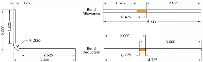
لنأخذ قوسًا بسيطًا على شكل حرف L كمثال. له ساقان، أحدهما بوصتان والآخر 3 بوصات، وسمك المادة 0.125 بوصة ونصف قطر الانحناء الداخلي 0.250 بوصة. زاوية الانحناء 90 درجة. لحساب طول السطح المسطح، لا تقيس من السطح الداخلي أو الخارجي، بل تأخذ في الاعتبار المحور المحايد. وهنا يُستخدم معامل K. يمثل معامل K موضع المحور المحايد كنسبة مئوية من سمك المادة. في هذه العملية الحسابية، سنستخدم معامل K بقيمة 0.42 لتحديد بدل الانحناء الصحيح ونمط السطح المسطح.
الصيغة (انظر صيغ الانحناء) هي:
بدل الانحناء = الزاوية * (π / 180) * (نصف القطر + عامل K * السمك).
بإدخال أرقامنا، لدينا: بدل الانحناء = 90 * (π / 180) * (0.250 + 0.42 * 0.125) = 0.475″
إذن، طول النمط المسطح هو ١٫٦٢٥ بوصة + ٢٫٦٢٥ بوصة + ٠٫٤٧٥ بوصة، أي ما يعادل ٤٫٧٢٥ بوصة. لذا، إذا جمعتَ طول جميع الحواف المسطح وأضفتَ بدل انحناء واحد لكل مساحة انحناء، فستحصل على طول القطعة المسطح الصحيح.
الآن، ألقِ نظرة فاحصة على الرسم. في تصميم الصفائح المعدنية العملية، تُعطى الأبعاد عادةً لتقاطع الحواف - وهذا ما يُعرف باسم خط القالب. لذلك، يجب طرح ضعف سُمك المادة بالإضافة إلى نصف قطر الانحناء من الإجمالي لحساب مساحة كل انحناء. تُسمى هذه القيمة "التراجع". في مثل هذه الحالات، يكون استخدام تعويض الانحناء أسهل. يتيح لك تعويض الانحناء استخدام أبعاد خط القالب لكل حافة، ثم تعديل الإجمالي بإضافة قيمة تعويض واحدة لكل انحناء. هنا، يكون التعويض -0.275، وبالتالي يصبح 5 بوصات 4.725 بوصة بعد الطرح.
التعاريف:
بدل الانحناء = الزاوية * (π / 180) * (نصف القطر + عامل K * السُمك)
تعويض الانحناء = بدل الانحناء – (2 * التراجع)
الإرجاع الداخلي = tan (الزاوية / 2) * نصف القطر الخارجي
الإرجاع = tan (الزاوية / 2) * (نصف القطر + السمك)
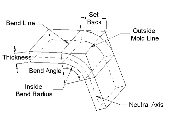
بدل الانحناء - طول القوس عبر منطقة الانحناء عند المحور المحايد.
زاوية الانحناء - الزاوية المتضمنة للقوس المتشكل بواسطة عملية الانحناء.
تعويض الانحناء مقدار تمدد المادة أو ضغطها نتيجة عملية الثني. يُفترض أن يحدث التمدد أو الضغط بالكامل في منطقة الثني.
خطوط الانحناء - الخطوط المستقيمة على الأسطح الداخلية والخارجية للمادة حيث تلتقي حدود الشفة بمنطقة الانحناء.
نصف قطر الانحناء الداخلي - نصف قطر القوس على السطح الداخلي لمنطقة الانحناء.
عامل K يُحدد موقع المحور المحايد. ويُقاس بقسمة المسافة من داخل المادة إلى المحور المحايد على سُمك المادة.
خطوط القالب في حالة الانحناءات التي تقل عن ١٨٠ درجة، تكون خطوط القالب هي الخطوط المستقيمة التي تتقاطع عندها أسطح الحافة التي تُحيط بمنطقة الانحناء. ويحدث هذا على السطحين الداخلي والخارجي للانحناء.
المحور المحايد - عند النظر إلى المقطع العرضي للانحناء، فإن المحور المحايد هو الموقع النظري الذي لا يتم فيه ضغط المادة أو تمديدها.
تراجع - بالنسبة للانحناءات التي تقل عن 180 درجة، يكون التراجع هو المسافة من خطوط الانحناء إلى خط القالب.
كيفية حساب عامل “K”:
على حد علمي، لا توجد صيغة لحساب عامل k. أنا متأكد من أن مهندسًا رياضيًا ما لديه صيغة في مكان ما. لكنها على الأرجح معقدة جدًا بحيث يصعب على معظمنا فهمها أو استخدامها.
معامل k هو النسبة المئوية لسمك المادة حيث لا يوجد تمدد أو ضغط للمادة في منطقة الانحناء. وبالتالي، المحور المحايد!
كلما كانت المادة أكثر صلابة، قلّ الضغط على الجانب الداخلي للثنية. وبالتالي، يزداد التمدد من الخارج، ويتحرك المحور المحايد نحو الداخل. أما المواد الأكثر ليونة، فتسمح بضغط أكبر من الداخل، ويبقى المحور المحايد أقرب إلى مركز سُمك المادة.
لنصف قطر الانحناء تأثير مماثل. كلما صغر نصف قطر الانحناء، زادت الحاجة للضغط، ويتحرك المحور المحايد نحو داخل الانحناء. أما مع نصف قطر أكبر، فيبقى المحور المحايد بالقرب من مركز سُمك المادة.
| عوامل K العامة | الألومنيوم | فُولاَذ | |
| نصف القطر | المواد الناعمة | المواد المتوسطة | المواد الصلبة |
| انحناء الهواء | |||
| 0 إلى سمك | 0.33 | 0.38 | 0.40 |
| سمك إلى 3 × سمك | 0.40 | 0.43 | 0.45 |
| أكبر من 3×سمك | 0.50 | 0.50 | 0.50 |
| القاع | |||
| 0 إلى سمك | 0.42 | 0.44 | 0.46 |
| سمك إلى 3 × سمك | 0.46 | 0.47 | 0.48 |
| أكبر من 3×سمك | 0.50 | 0.50 | 0.50 |
| سك النقود | |||
| 0 إلى سمك | 0.38 | 0.41 | 0.44 |
| سمك إلى 3 × سمك | 0.44 | 0.46 | 0.47 |
| أكبر من 3×سمك | 0.50 | 0.50 | 0.50 |
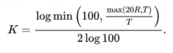
يمكن استخدام الصيغة التالية بدلاً من الجدول كتقريب جيد لعامل K لثني الهواء:
مخططات وصيغ حساب بدل الانحناء
لتسهيل فهم صيغة حساب طول الانحناء غير المطوي، أدرجنا لكم أربعة جداول معاملات شائعة، وشرحنا ست عشرة صيغة حسابية لطول الانحناء غير المطوي، مع بعض الأمثلة التوضيحية لفهم أفضل. نأمل أن يفيدكم هذا المحتوى عمليًا. لأي استفسار، تواصلوا معنا.
| عرض الأخدود على شكل حرف V/سمك اللوحة | 0.6 | 0.8 | 1.0 | 1.2 | 1.5 | 2.0 | 2.5 | 3.0 | 3.5 | 4.0 | 4.5 | 5.0 | أقصر حجم |
| الإصدار 4 | 0.9 | 1.4 | 2.8 | ||||||||||
| V6 | 1.5 | 1.7 | 2.0 | 4.5 | |||||||||
| الإصدار 7 | 1.8 | 2.1 | 2.4 | 5.0 | |||||||||
| محرك V8 | 1.9 | 2.2 | 2.5 | 5.5 | |||||||||
| الإصدار 10 | 2.1 | 2.3 | 2.7 | 7.0 | |||||||||
| الإصدار 12 | 2.2 | 2.5 | 2.8 | 3.4 | 8.5 | ||||||||
| الإصدار 14 | 3.5 | 3.8 | 6.4 | 6.8 | 10.0 | ||||||||
| الإصدار 16 | 3.1 | 3.8 | 4.5 | 5.0 | 11.0 | ||||||||
| الإصدار 18 | 3.3 | 4.0 | 13.0 | ||||||||||
| الإصدار 20 | 4.0 | 4.9 | 5.1 | 6.6 | 7.2 | 7.8 | 14.0 | ||||||
| الإصدار 25 | 4.4 | 5.0 | 5.5 | 6.8 | 7.8 | 8.3 | 16.5 | ||||||
| الإصدار 32 | 5.0 | 5.5 | 6.1 | 8.7 |
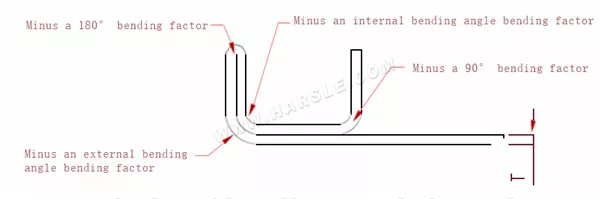
ملحوظة: عندما يتم وضع علامة على حجم الرسم البياني للجزء بالتسامح السلبي، يمكن زيادة قيمة عامل الانحناء، كما هو موضح في الجدول، يمكن زيادة الجزء الأحمر إلى: 2.8؛ 2.82؛ 3.4؛ 3.43 أو 3.44: 4.5؛ 4.6؛ 5.5: 5.6
| سماكة مم\زاوية | أخدود القالب عرض | 90 درجة | الزاوية الداخلية | الزاوية الخارجية | 180 درجة | ||
| 1.5 | الإصدار 10 | 3.0 | 3.2 | 4.1 | 0.8 | ||
| 2.0 | الإصدار 12 | 3.8 | 3.7 | 4.6 | 1.0 | ||
| 2.5 | الإصدار 16 | 4.5 | 4.8 | 6.1 | 1.3 | ||
| سماكة مم\زاوية | 30 درجة | 45 درجة | 60 درجة | 120 درجة | 135 درجة | 145 درجة | |||||||||
| 1.0 | 0.35 | 0.7 | 1.1 | 1.0 | 0.6 | 0.4 | |||||||||
| 1.2 | 0.4 | 0.8 | 1.2 | 1.0 | 0.6 | 0.4 | |||||||||
| 1.5 | 0.5 | 1.0 | 1.6 | 1.4 | 0.9 | 0.6 | |||||||||
| 2.0 | 0.6 | 1.2 | 2.0 | 1.7 | 1.1 | 0.7 | |||||||||
| 2.5 | 0.8 | 1.6 | 2.6 | 2.2 | 1.4 | 0.85 | |||||||||
| 3.0 | 1.0 | 2.2 | 3.4 | 2.8 | 2.0 | 1.2 | |||||||||
| 4.0 | 3.7 | 2.4 | 1.4 | ||||||||||||
| سمك مم | 0.5 | 1.0 | 1.2 | 1.5 | 2.0 | 2.5 | 3.0 | 4.0 | 5.0 | 6.0 | |||||
| ثقب العملية مم | 1.لا يوجد ثقوب 2.يمكن فتح ثقب φ2 | φ2 | φ2.5 | φ3.0 | φ3.5 | φ4.0 | φ5.5 | φ6.0 | φ7.0 | ||||||
ملحوظة: إذا تم السماح باحتياجات خاصة، يمكن استخدام درجة أكبر من الفتحة.
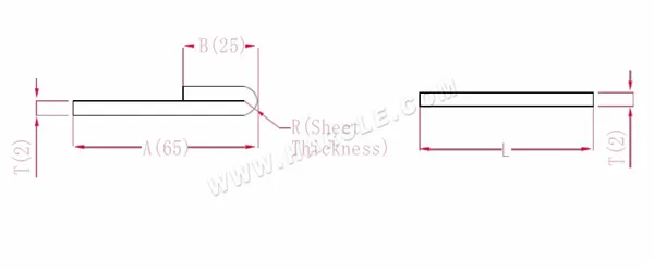
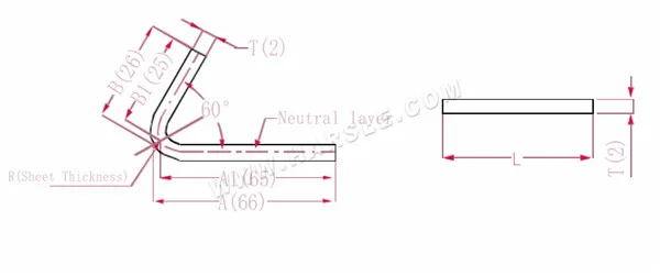
الرسم التخطيطي وصيغة الحساب للانحناء الواحد
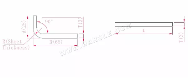
أ، ب—طول ثني قطعة العمل
P'—معامل انحناء الحافة (عامل الانحناء: عامل واحد ناقص انحناء واحد)
R— الانحناء والقطع (سمك اللوحة عمومًا)
سمك المادة T
الطول الموسع L=A+B-P'، وهو L=25+65-5.5=84.5
وفقًا للجدول 1، سمك اللوحة هو 3، والقالب السفلي هو V25، ومعامل الانحناء هو 5.5
ملاحظة: وفقًا للجدول 1، فإن معاملات الانحناء المختلفة للقوالب السفلية وسمك اللوحة المختلفة تختلف.
رسم تخطيطي وصيغة حسابية للانحناء المزدوج
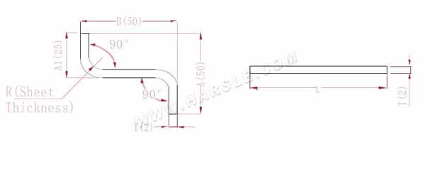
أ(أ1)، ب— طول ثني قطعة العمل
P'—معامل انحناء الحافة (عامل الانحناء: عامل واحد ناقص انحناء واحد)
R— الانحناء والقطع (سمك اللوحة عمومًا)
سمك المادة T
الطول الموسع L=A+T+B-2*P'، وهو L=50+2+50-2*3.4=95.2
وفقًا للجدول 1، سمك اللوحة هو 2، والقالب السفلي هو V12، ومعامل الانحناء هو 3.4
ملاحظة: وفقًا للجدول 1، فإن معاملات الانحناء المختلفة للقوالب السفلية وسمك اللوحة المختلفة تختلف.
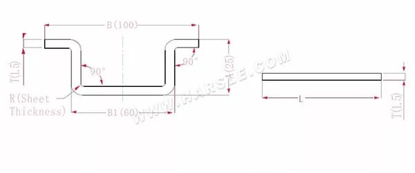
رسم تخطيطي وصيغة حسابية للانحناء الثلاثي

A(A1)، B (B1)-طول ثني قطعة العمل
P'—معامل انحناء الحافة (عامل الانحناء: عامل واحد ناقص انحناء واحد)
R— الانحناء والقطع (سمك اللوحة عمومًا)
سمك المادة T
الطول الموسع L=A+T+B+T-3*P'، وهو L=50+2+90+2-3*3.4=133.8
وفقًا للجدول 1، سمك اللوحة هو 2، والقالب السفلي هو V12، ومعامل الانحناء هو 3.4
ملاحظة: وفقًا للجدول 1، فإن معاملات الانحناء المختلفة للقوالب السفلية وسمك اللوحة المختلفة تختلف.
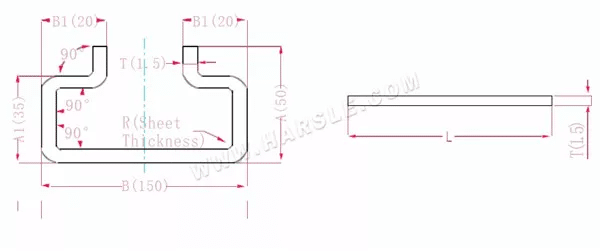
رسم تخطيطي وصيغة حسابية للانحناءات الأربعة
أ، ب (ب1)-طول ثني قطعة العمل
P'—معامل انحناء الحافة (عامل الانحناء: عامل واحد ناقص انحناء واحد)
R— الانحناء والقطع (سمك اللوحة عمومًا)
سمك المادة T
الطول الموسع L=A+A+B+T+T-4*P'، وهو l = 25+25+100+1.5+1.5-4 * 2.8 = 141.8
وفقًا للجدول 1، يبلغ سمك اللوحة 1.5، والقالب السفلي هو V12، ومعامل الانحناء هو 2.8
ملاحظة: وفقًا للجدول 1، فإن معاملات الانحناء المختلفة للقوالب السفلية وسمك اللوحة المختلفة تختلف.
رسم تخطيطي وصيغة حسابية للانحناءات الستة
A(A1)، B (B1)-طول ثني قطعة العمل
P'—معامل انحناء الحافة (عامل الانحناء: عامل واحد ناقص انحناء واحد)
R— الانحناء والقطع (سمك اللوحة عمومًا)
سمك المادة T
طول التمدد L=A+T+A+T+B+B1+B1-6*P'
وهو l = 50+1.5+50+1.5+150+20+20-6 * 2.8 = 276.2
وفقًا للجدول 1، يبلغ سمك اللوحة 1.5، والقالب السفلي هو V12، ومعامل الانحناء هو 2.8
ملاحظة: وفقًا للجدول 1، فإن معاملات الانحناء المختلفة للقوالب السفلية وسمك اللوحة المختلفة تختلف.
مخطط وصيغة حساب الانحناء بزاوية 180 درجة
أ، ب—طول ثني قطعة العمل
P'—معامل انحناء الشريحة المسطحة
R— الانحناء والقطع (سمك اللوحة عمومًا)
سمك المادة T
الطول الموسع L=A+B-P'، وهو L=25+65-1=89
وفقًا للجدول 2، سمك اللوحة هو 2، والقالب السفلي هو V12، وعامل الانحناء هو نصف سمك اللوحة
ملاحظة: وفقًا للجدول 2، فإن اختيار القالب السفلي المختلف له معاملات انحناء مختلفة وسمك لوحة مختلف.
مخطط وصيغة حساب الانحناء ثنائي الطبقة
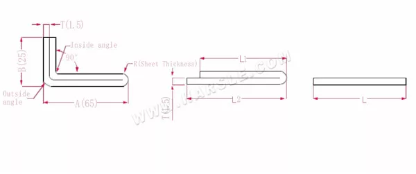
أ، ب—طول ثني قطعة العمل
P1—معامل الانحناء للزاوية الداخلية
P2—معامل الانحناء لزاوية الانحناء الخارجية
R— الانحناء والقطع (سمك اللوحة عمومًا)
سمك المادة T
الطول الموسع L1=(A-1.5) +(B-1.5)-P1، وهو L1= (65-1.5) +(25-1.5)-3.2=83.8
L2=A+B-P2، أي أن L2=65+25-4.1=85.9
L=L1+L2-T/2، أي L=83.8+85.9-0.75=168.95
وفقًا للجدول 2، سمك اللوحة هو 1.5، والقالب السفلي هو V12، ومعامل انحناء الزاوية الداخلية هو 3.2، ومعامل انحناء الزاوية الخارجية هو 4.1، ومعامل الانحناء 180 هو 0.75.
ملاحظة: وفقًا للجدول 2، فإن معاملات الانحناء المختلفة للقوالب السفلية وسمك اللوحة المختلفة تختلف.
مخطط وصيغة حساب الانحناء المزدوج الطبقة بحافة واحدة
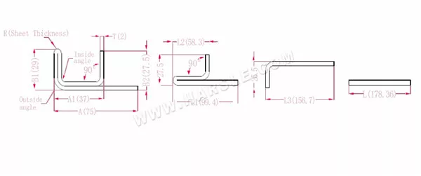
أ، أ1، أ2، ب1، ب2، ل، ل1، ل2، ل3— طول ثني قطعة العمل
P1—معامل الانحناء للزاوية الداخلية
P2—معامل الانحناء لزاوية الانحناء الخارجية
R— الانحناء والقطع (سمك اللوحة عمومًا)
سمك المادة T
الطول الموسع L1=(A1-T) +(B2-T)-P1 وهو L1= (35-2) +(34-2)-3.7=61.3
L2=(B1-T) +(A2-T)-P1، وهو ما يساوي L2= (50-2) +(34-2)-3.7=76.3
L3=A+B1+B2-2*P2، أي أن L3=70+35+50-2*4.6+145.8
L=L1+L2+L3-2*P3، أي L=61.3+75.3+145.8-2*1=280.4
وفقًا للجدول 2، سمك اللوحة هو 2، والقالب السفلي هو V12، ومعامل انحناء الزاوية الداخلية هو 3.7، ومعامل انحناء الزاوية الخارجية هو 4.6، ومعامل الانحناء 90 هو 1.
ملاحظة: وفقًا للجدول 2، فإن معاملات الانحناء المختلفة للقوالب السفلية وسمك اللوحة المختلفة تختلف.
مخطط وصيغة حساب الانحناء ثنائي الطبقة مع حافتين
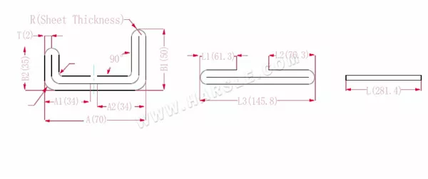
أ، أ1، أ2، ب1، ب2، ل، ل1، ل2، ل3— طول ثني قطعة العمل
P1—معامل الانحناء للزاوية الداخلية
P2—معامل الانحناء لزاوية الانحناء الخارجية
R— الانحناء والقطع (سمك اللوحة عمومًا)
سمك المادة T
الطول الموسع L1=(A1-T) +(B2-T)-P1 وهو L1= (35-2) +(34-2)-3.7=61.3
L2=(B1-T) +(A2-T)-P1، وهو ما يساوي L2= (50-2) +(34-2)-3.7=76.3
L3=A+B1+B2-2*P2، أي أن L3=70+35+50-2*4.6+145.8
L=L1+L2+L3-2*P3، أي L=61.3+75.3+145.8-2*1=280.4
وفقًا للجدول 2، سمك اللوحة هو 2، والقالب السفلي هو V12، ومعامل انحناء الزاوية الداخلية هو 3.7، ومعامل انحناء الزاوية الخارجية هو 4.6، ومعامل الانحناء 90 هو 1.
ملاحظة: وفقًا للجدول 2، فإن معاملات الانحناء المختلفة للقوالب السفلية وسمك اللوحة المختلفة تختلف.
مخطط وصيغة حساب انحناء الخطوة

أ، ب—طول ثني قطعة العمل
R— الانحناء والقطع (سمك اللوحة عمومًا)
سمك المادة T
الطول غير المطوي L=A+1
ملحوظة: عندما تصبح الخطوة مساوية لسمك لوحين، أضف 0.5 لكل خطوة و1 لكل خطوة.
رسم بياني وصيغة حساب زاوية الانحناء الخاصة 1
A(A1)، B (B1)-طول ثني قطعة العمل
P'—معامل انحناء الحافة (عامل الانحناء: عامل واحد ناقص انحناء واحد)
R—الانحناء والقطع (سمك اللوحة عمومًا)
سمك المادة T
طول التمدد L=(AT) +(BT)-P'، وهو L= (66-1) +(26-1)-2=65+25-2=88
وفقًا للجدول 3، سمك اللوحة هو 2، والقالب السفلي هو V12، ومعامل الانحناء 60 هو 2
ملاحظة: وفقًا للجدول 3، يتم اختيار الطبقة المحايدة كطول وعرض الانحناء.
رسم بياني وصيغة حساب زاوية الانحناء الخاصة 2
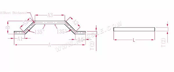
أ (أ1، أ2، أ3، أ4)، ب— طول ثني قطعة العمل
P— عامل الانحناء لـ 135 زاوية انحناء
R— الانحناء والقطع (سمك اللوحة عمومًا)
سمك المادة T
طول التمدد L = A1+A2+A3+A2+A4-PP.
ملاحظة: نفس خطوة الضغط الانحناء تحتاج فقط إلى تقليل معاملين
وفقًا للجدول 3: سمك اللوحة هو 2، والقالب السفلي هو V12، ومعامل الانحناء عند 135 هو 1.1.
رسم بياني وصيغة حساب زاوية الانحناء الخاصة 3

أ (أ1، أ2)، ب (ب1، ب2)-طول ثني قطعة العمل
P1—معامل الانحناء 120 درجة
P2—معامل الانحناء 145 درجة
P3—معامل الانحناء 90 درجة
R— الانحناء والقطع (سمك اللوحة عمومًا)
سمك المادة T
ملاحظة: إذا تم تحديد الحجم الرسومي على الشكل، فيجب تحويل حجم الشكل إلى حجم الطبقة المحايدة عند حساب طول الفتح؛
طول التمدد L=A11+B11+B21+A21-P1-P2-P3، وهو l = 80+50+103+70-1.7-0.7-3.4 = 297.2
وفقًا للجدول 3: سمك اللوحة هو 2، والقالب السفلي هو V12، ومعامل الانحناء 120 هو 1.7، ومعامل الانحناء 145 هو 0.7، ومعامل الانحناء 90 هو 3.4
ملاحظة: وفقًا للجدول 3، فإن معاملات الانحناء المختلفة للقوالب السفلية وسمك اللوحة المختلفة تختلف.
مخطط وصيغة حساب الربط المشترك 1
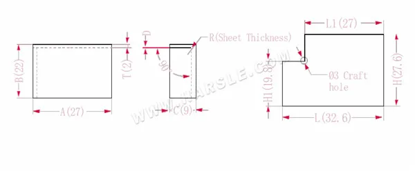
أ، ب، ج— طول وعرض وارتفاع حافة ثني قطعة العمل
P— معامل الانحناء
R— الانحناء والقطع (سمك اللوحة عمومًا)
H(H1)، l (L1)-الطول غير المطوي لكل جانب
سمك المادة T
د- خلوص عملية الانحناء (عادةً 0~0.5)
الطول الموسع L1=A، وهو L1=27
L=A+CP، أي L=27+9-3.4=32.6
H1=BTD، أي H1=22-2-0.2=19.8. ملاحظة: D يساوي 0.2.
H=B+CP، أي H=22+9-3.4=27.6
وفقًا للجدول 1: سمك اللوحة هو 2، والقالب السفلي هو V12 ومعامل الانحناء هو 3.4
ملاحظة: وفقًا للجدول 1، فإن معاملات الانحناء المختلفة للقوالب السفلية وسمك اللوحة المختلفة تختلف.
مخطط وصيغة حساب الرابطة المشتركة 2
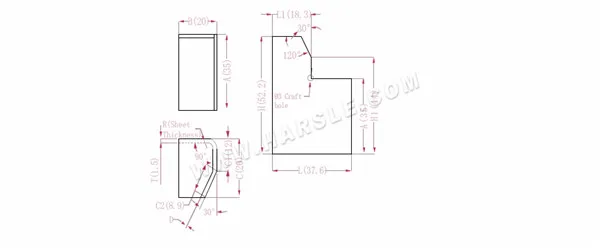
أ، ب، ج— طول وعرض وارتفاع حافة ثني قطعة العمل
H(H1)، L (L1)-الطول غير المطوي لكل جانب
P—معامل الانحناء 90° P1—معامل الانحناء 30°
R— الانحناء والقطع (سمك اللوحة عمومًا)
سمك المادة T
د- خلوص عملية الانحناء (عادةً 0~0.5)
الطول الموسع L1=BTD، وهو L1=20-1.5-0.2=18.3
L=B+C1+C2-P-P1، أي L=20+12+8.9-2.8-0.5=37.6
H1=C1+APD، أي H1=12+35-2.8-0.2=44. ملاحظة: D يساوي 0.2.
H=A+CP، أي H=35+20-2.8=52.2
وفقًا للجدول 1: سمك اللوحة هو 1.5، والقالب السفلي هو V12، ومعامل الانحناء هو 2.8، ومعامل الانحناء 30 هو 0.5
ملاحظة: وفقًا للجدول 1، فإن معاملات الانحناء المختلفة للقوالب السفلية وسمك اللوحة المختلفة تختلف.
مخطط وصيغة حساب الرابطة المشتركة 3
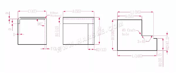
أ، ب، ج— طول وعرض وارتفاع حافة ثني قطعة العمل
H(H1)، L (L1)-الطول غير المطوي لكل جانب
P— معامل الانحناء
R— الانحناء والقطع (سمك اللوحة عمومًا)
سمك المادة T
د- خلوص عملية الانحناء (عادةً 0~0.5)
الطول الموسع H1 = B-B1-D، أي H1 = 50 - 12 - 0.3 = 37.7. ملاحظة: D = 0.2.
H2=BTD وهو H2=50-2.5-0.3=47.2
H=B+C+B1-2*P، أي أن H=50+47+12-2*4.5=100
L1=A+CTDP، وهو L1=55+47-2.5-0.3-4.5=94.7
L=A+C+B2-2*P، أي L=55+47+12-2*4.5=105
وفقًا للجدول 1: سمك اللوحة هو 1.5، والقالب السفلي هو V16 ومعامل الانحناء هو 4.5
ملاحظة: وفقًا للجدول 1، فإن معاملات الانحناء المختلفة للقوالب السفلية وسمك اللوحة المختلفة تختلف.

America-Customer-Feedback-1.jpg)
America-Miami-Customer-Feeback-1.jpg)
Uzbekistan-Customer-Feedback1.png)
Kosovo-Customer-Feedback11.png)
Russia-Customer-Feedback.jpg)
Russia-Customer-Feedback-3.jpg)


