Entwurf der Steuerung der Scherwinkeleinstellung durch das Hydrauliksystem einer Guillotine-Schermaschine
In my experience with guillotine shearing machines, I have focused on the design of controlling shear angle adjustment by hydraulic systems. This aspect is critical for achieving precise cuts and improving overall efficiency in metal fabrication. The ability to adjust the shear angle dynamically allows for greater flexibility in handling various materials and thicknesses. In this article, I will share insights into the design considerations, benefits, and operational mechanisms of hydraulic systems for shear angle adjustment, highlighting how these advancements can enhance performance in industrial applications.
Overview of the Shear Angle Adjustment

With the development of Chinese manufacturing industry. The development of Schermaschinen has increasingly become the mainstay of the machinery manufacturing industry. Universal high-performance shearing machines are widely used in aviation, automotive, agricultural machinery, motors, electrical appliances, instrumentation, medical equipment, home appliances, hardware and other industries. In recent years, with the development of mold technology and stamping technology, the application range of shearing machines has been continuously expanding, and the number is constantly increasing.
In the design of the shearing machine system, the system is different. When the system controls the change of the shear angle, there is a change in the angle of the entire tool holder. The change of the shear angle has strict requirements on the accuracy of the sheet material. The specifications of the sheets are different for different purposes.
Hydraulic system
The schematic diagram of the hydraulic system is shown in Figure 1.
(1) Press lightly. The oil from the oil pump motor set 1 is built through the main pressure valve 7 to build pressure, through the cartridge valve 8 and the check valve 10, and enters the presser foot. Because the sequence valve 12 has a certain sequence pressure, the pressure angle is depressed, the upper chamber of the cylinder is not built up, and the knife holder does not move, resulting in a light pressure action.
(2) Cut. After the light pressure is completed, the oil opens the sequence valve 12, and the upper chamber of the cylinder builds pressure. The oil in the lower chamber of the small cylinder passes through the hydraulic control valve in the lower chamber 5. The safety valve in the lower chamber 4. The back pressure valve 9 returns to the oil tank. The oil in the series chamber remains unchanged from the lower chamber of the large cylinder to the upper chamber of the small cylinder.
(3) Return. After the shearing is completed, the oil from the oil pump motor unit 1 is built through the main pressure valve 7 to build through the lower chamber insert valve 6 to the lower chamber of the small cylinder. The oil in the upper chamber of the large cylinder passes through the oil return valve 13 in the upper chamber. The oil at the press angle is returned to the tank via the presser foot return valve 11.
(4) The shear angle becomes larger. The oil pump motor set 1 enters the lower chamber of the small cylinder through the lower chamber reversing valve 3 after the pressure is built. The oil in the series chamber has a shear angle control valve 2 to control the shear angle valve 14 to be sealed, and the large chamber of the cylinder remains unchanged. The shear angle becomes smaller.
(5) The shear angle becomes smaller. The oil pump motor set 1 enters the upper chamber of the small cylinder through the lower chamber reversing valve 3 after the pressure is built. The oil in the series chamber has a shear angle control valve 2 to control the shear angle valve 14 to be sealed, and the large chamber of the cylinder remains unchanged. The shear angle becomes larger.
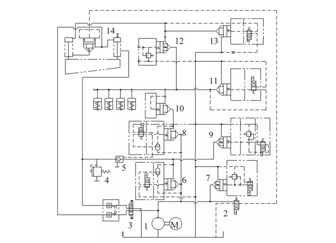
1. Oil pump motor unit 2. Shear angle control valve 3. Lower chamber directional valve 4. Lower chamber safety Valve 5. Lower chamber hydraulic control valve 6. Lower chamber cartridge valve 7. Main pressure valve 8. Cartridge valve 9. Back pressure valve 10. One-way valve 11. Pressure foot return valve 12. Sequence valve 13. Upper Cavity oil return valve 14. Shear angle valve
The change of the shear angle adjustment of the system uses the insertion valve control to make the machine tool change very accurately when the shear angle changes. The ordinary shearing machine uses the area ratio relationship between the oil cylinders to control. When the shear angle changes, there are varying degrees of change. Because the function of the cartridge valve is similar to the switching element of the logic system, the structure of the spool is a cone seal, and the oil path is cut off by the cone seal to distinguish it from the ordinary directional valve.
Cartridge valve can not only achieve various action requirements of ordinary hydraulic valve, but also has lower flow resistance and larger flow capacity than ordinary hydraulic valve; fast action speed; good sealing, less leakage; simple structure and easy manufacturing; Reliable work; one valve is versatile; easy to integrate; the requirements for low viscosity are not high, and the use of cartridge valves significantly reduces the installation size and weight.
Cartridge valves and integrated systems, as a new generation of hydraulic control technology, are the development and complement of traditional hydraulic control components. At present, it has been used in a large number of applications in my country’s machinery, metallurgy, chemical industry and shipping industries. Among them, integrated systems that all use cartridge valves are used more. Hybrid integrated system, that is, the main system is mainly a cartridge valve, and the auxiliary system uses ordinary hydraulic valves.
Due to taking full advantage of their respective advantages, a cartridge valve as a controllable hydraulic resistance can be added or piloted. The control signal can be adjusted, and it can also be affected by the hydraulic and mechanical feedback signals from the actuator. It can only control the working state of an oil circuit: when the oil circuit is cut off, the hydraulic resistance is infinite; the oil circuit is throttled When the fluid resistance is between zero and infinity. therefore,
A cartridge valve can only form a two-way circuit.
For the change of shear angle adjustment, we used a cartridge valve between the series of cylinders, which was controlled by a directional valve. Simultaneously control the oil in and out of the two oil chambers, which constitutes an oil return circuit with directional valve control, forming a single hydraulic system that changes the shear angle. No effect on other actions. It is controlled when the shear angle is changed. The accuracy is high when the shear angle is changed, and the accuracy is greatly increased when cutting the sheet, thereby meeting customer needs.
Calculation of Hydraulic System Components
(1) Calculation of cylinder pressure
P=S/A=24000/0.00089=27 (Pa)
As can be seen from the above formula, the establishment of the pressure value is caused by the presence of a load. On the effective working area of the same piston, the greater the load force, the greater the pressure required to overcome the load force.
(2) Flow between series chambers: the upper chamber of the large cylinder and the lower chamber of the small cylinder are connected in series
Q =V/T =π/4D²v ×10³=0.785 ×0.175 ×3.06 ×1000=420 (L/min)
In the formula: V-the volume of the effective cross section of the oil passing through the cylinder in a unit time, that is, the consumption.
(3) Piston movement speed
When the piston is extended: ν=4Qην/πD ×10-3=4 ×420 ×
1/3.14×0.175×0.001=0.09 (m/min)
When the piston rod retracts: ν=4Qην/π (D2- d2)×10-3
=4×420×1/3.14×(0.1752- 0.0982)×0.001=0.01(M/min)
(4) Inner diameter of cylinder
D = (√4P1/πP )×10-3m = (√ 4×2000/3.14×21) ×
0.001=0.23 (m)
Abschluss
The design of a hydraulic system for controlling shear angle adjustment in guillotine shearing machines involves careful consideration of components, control mechanisms, and safety features. By optimizing these elements, manufacturers can enhance the performance and versatility of their shearing machines, ensuring high-quality cuts and efficient operation.
Obvious economic effects have been achieved through the above technology, which makes the machine tool more stable and reliable and eliminates the change of the shear angle during the shearing of the sheet. The new system uses a digital display to change its parameters for adjustment, which has a very high stability. State accuracy and better dynamic performance indicators, the system allows different angles for sheet shearing with different customer requirements, so that the machine tool can not only improve the accuracy but also meet the requirements of different customers. The service life of the oil pump is increased, and the oil temperature is reduced to ensure that the system can run continuously for a long time.