


El modo manual de la DELEM DA-66S ofrece a los usuarios la flexibilidad de realizar operaciones de plegado precisas independientemente de los ajustes automáticos. Con el modo manual, los operadores pueden tener control total sobre el proceso de plegado, personalizando los parámetros para cada trabajo. Este modo es ideal para aplicaciones que requieren ajustes específicos que los ajustes automáticos no pueden realizar.
En este artículo, profundizaremos en las funcionalidades principales del modo manual DELEM DA-66S, brindándole una guía completa para mejorar el rendimiento y la producción de su máquina.
Descripción general del modo manual
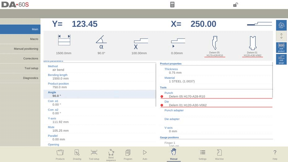
El modo manual DELEM DA-66S otorga a los usuarios la capacidad de controlar manualmente el prensa plegadora, independiente de los programas predefinidos. Al navegar al Modo Manual, puede ver en pantalla las posiciones en tiempo real de los ejes clave, como el eje Y y el eje X principal. Estos indicadores garantizan que los marcadores de referencia estén correctamente alineados con los valores programados para operaciones de plegado precisas.
En el modo manual, se programan los parámetros para un plegado. Este modo es útil para pruebas, calibración y plegados individuales.
El modo manual es independiente del modo automático y se puede programar independientemente de los programas en la memoria.
En la parte superior de la pantalla del modo Manual, se encuentran las posiciones actuales del eje Y y del eje X principal. Todos los demás ejes y funciones se listan uno por uno en las dos columnas siguientes. Cuando estos valores del eje Y y del eje X están resaltados, significa que se han encontrado los marcadores de referencia de estos ejes y que están posicionados correctamente respecto a sus valores programados.
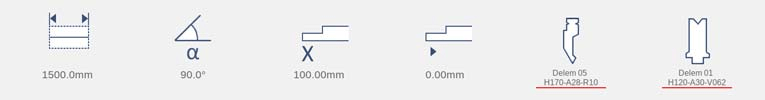
Sobre los ejes y funciones, iconos grandes (mosaicos) con valores relacionados muestran los más utilizados. Estos mosaicos se pueden seleccionar y sus valores se pueden modificar directamente.
A continuación se muestra una lista de los parámetros disponibles en el modo manual.
Parámetros de curvatura
Método
Seleccione el método de plegado necesario. El control admite los siguientes métodos estándar:
• Curva de aire
• Tocar fondo
• Dobladillo
• Dobladillos y bajos

Los métodos de curvatura se han explicado con más detalle en el modo Programa.
Método de desvío
Dinámico: El coronamiento se controlará automáticamente en tiempo real durante el plegado, aplicando las correcciones adecuadas cuando sea necesario.
No dinámico: La coronación se comportará como una coronación hidráulica estándar; no habrá correcciones en tiempo real.
Longitud de curvatura
Programa la longitud de curvatura de la chapa.
Posición del producto
El valor de la posición absoluta del producto en la dirección Z. El lado izquierdo de la máquina es la posición de referencia cero.
Ángulo
Angulo a doblar.
Corr.α 1, Corr.α 2
Corrección del ángulo de curvatura.
La corrección del ángulo debe ingresarse como lo indican los siguientes ejemplos:
Valor programado de 90 grados. Valor medido de 92 grados. Luego, se requiere programar Corr.α con -2.
Valor programado de 90 grados. Valor medido de 88 grados. Luego, se requiere programar Corr.α con +2.
Apertura del dobladillo
El dobladillo se puede realizar con una distancia de apertura determinada entre las dos bridas. El valor de la apertura se utilizará para calcular la posición del plegador durante el proceso de dobladillo.
De forma predeterminada, este parámetro tiene el valor del parámetro del modo Configuración Apertura de dobladillo predeterminada.
Dobladillo rápido
Al activar el engrapado rápido, el eje Y se moverá a alta velocidad hacia abajo en cuanto se encuentre por debajo de la parte superior del troquel, hasta alcanzar la abertura de carga. Esto reducirá el tiempo del ciclo, especialmente al engrapar con un troquel en U.
Sólo disponible cuando lo habilita el fabricante de la máquina.
Corr.Y
Corrección en la posición del eje Y, en caso de que se haya seleccionado el fondo.
Eje Y
El valor del eje Y programado o calculado para realizar un ángulo determinado.
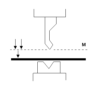
Silenciar
Punto de secuencia donde el eje Y cambia de velocidad de cierre rápido a velocidad de prensado. Se programa aquí como valor de posición del eje Y. El valor programado es el punto del eje Y sobre la chapa.
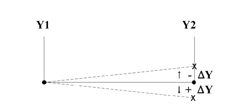
Paralelo
Diferencia entre los cilindros izquierdo y derecho (Y1 e Y2). Si es positivo, el lado derecho está más bajo. Si es negativo, el lado derecho está más alto. El valor programado está activo por debajo del punto de sujeción.
Apertura
Este parámetro genera una cierta abertura entre el punzón y la matriz después del plegado. Un valor positivo indica la abertura por encima de Mute, y un valor negativo por debajo de Mute.
Cuando desee limitar el tiempo de manipulación del producto, puede programar un pequeño valor positivo o negativo.
Fuerza
Fuerza
La fuerza programada aplicada durante el prensado.
Tiempo de permanencia
Tiempo de retención del punzón en el punto de flexión.
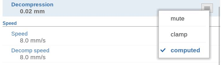
Descompresión
Distancia de descompresión tras la flexión para liberar la presión de trabajo del sistema. La distancia de descompresión se puede ajustar opcionalmente a un punto específico del ciclo. De forma estándar, se calcula la distancia de descompresión, cuyo valor es el mínimo requerido. Opcionalmente, se puede elegir entre Mute (el punto de mute calculado) o Clamp (el punto de sujeción calculado). Ambas opciones tienen una distancia mayor que la calculada.
Velocidad
Velocidad
Velocidad de prensado, la velocidad del eje Y durante el plegado.
Velocidad de descomposición
La velocidad de descompresión es la velocidad programable del haz durante la distancia de descompresión.
Funciones
Esperar la retractación
En caso de retracción, deje que el eje Y espere hasta que finalice la retracción, sí o no.
No: la retracción se inicia cuando el eje Y pasa el punto de sujeción, el eje Y no se detiene.
Sí: cuando el eje Y alcanza el punto de sujeción, se detiene y se inicia la retracción. Al finalizar la retracción, el eje Y continúa su movimiento.
Propiedades del producto
Espesor
Programa el espesor de la chapa.
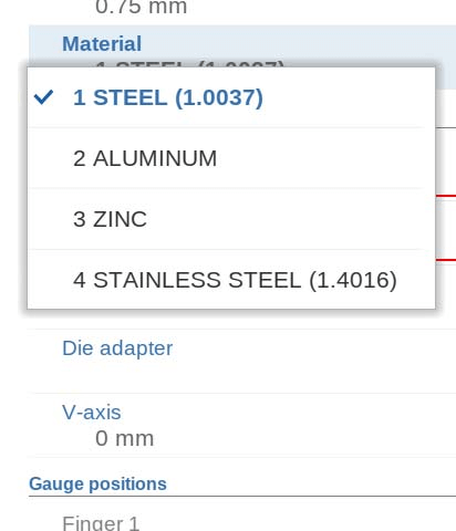
Material
Selección de uno de los materiales programados para calcular las profundidades de plegado. El control incluye 4 materiales preprogramados. Se pueden programar un total de 99 materiales. Estos materiales se programan en la página Materiales del modo Configuración.
Herramientas
Puñetazo
El nombre (ID) del punzón seleccionado. Pulse para modificarlo o seleccionarlo de la biblioteca de punzones.
Morir
El nombre (ID) del troquel seleccionado. Pulse para modificarlo o seleccionarlo de la biblioteca de troqueles.
Adaptador de punzón
El nombre (ID) del adaptador de punzón seleccionado. Pulse para modificarlo o seleccionarlo de la biblioteca de adaptadores de punzón. La programación de un adaptador depende del parámetro "Usar adaptador de punzón" en el modo Máquina.
Adaptador de matriz
El nombre (ID) del adaptador de matriz seleccionado. Pulse para modificarlo o seleccionarlo de la biblioteca de adaptadores de matriz. La programación de un adaptador depende del parámetro "Usar adaptador de matriz" en el modo Máquina.
Posiciones del indicador
Dedo (1/2/3/4)
La posición del dedo (contacto), correspondiente a la posición del eje X y la posición de apoyo.
Ejes auxiliares
Eje auxiliar
Si tiene uno o más ejes auxiliares (por ejemplo, un eje X, un eje R o un eje Z), sus parámetros aparecen aquí. Si tiene un eje R1 y un eje R2, el valor programado del eje R1 se copia automáticamente al valor del eje R2. El valor del eje R2 puede modificarse posteriormente si es necesario.
Retraer
Distancia de retracción del eje durante la curva. La retracción del tope trasero se inicia en el punto de pinzamiento.
Velocidad
Velocidad del eje en la curva actual. Se puede programar como porcentaje de la velocidad máxima posible.
Soporte de piezas
Eje PST
Con este parámetro se puede activar o desactivar el soporte de la pieza. Al desactivarlo, el soporte se mantendrá en su posición cero durante el plegado.
Posición R
Altura del soporte de la pieza antes y después del plegado. Por defecto, la altura se establece en la parte superior de la matriz (posición R = 0,00 mm). Solo disponible si el fabricante de la máquina lo habilita.
Método
En el modo manual del DELEM DA-66S, puede controlar cómo y cuándo el soporte de la pieza vuelve a su posición cero tras completar un plegado. Las opciones incluyen configurar el soporte para que vuelva cuando el eje Y alcance la UDP (Retorno en UDP) o iniciar el retorno en cuanto el eje Y comience a abrirse (Retorno al abrir).
Como alternativa, puede usar la opción "Inclinación del producto" para añadir una inclinación adicional y evitar la colisión entre el producto y el punzón durante la apertura del eje Y. La opción "Soporte de ángulo estático" permite que el soporte de la pieza se mantenga en un ángulo fijo, convirtiéndolo en una mesa de apoyo estable en lugar de seguir los movimientos del producto. Cada opción ofrece ventajas únicas para optimizar las operaciones de la máquina en el modo manual de la DELEM DA-66S.
Ángulo de inclinación
El ángulo de inclinación determina el movimiento del soporte de la pieza. En la parte frontal de la máquina, el soporte se mueve a una posición más alta (ángulo mayor), mientras que en la parte trasera, se mueve a una posición más baja (ángulo menor). Esta función es aplicable al usar el método de "Inclinación del producto".
Velocidad de inclinación
Esto especifica la velocidad a la que la pieza se mueve hasta el ángulo de inclinación, expresada como porcentaje de la velocidad máxima de operación. Solo es relevante cuando se selecciona "Inclinación del producto" en el modo manual del DELEM DA-66S.
Espacio libre de inclinación
Si la distancia de descompresión es insuficiente para el movimiento de inclinación, se puede programar una distancia de inclinación adicional. Esta distancia adicional se incluye en la distancia de descompresión programada, lo que garantiza un funcionamiento fluido. El ajuste de distancia se utiliza exclusivamente con el método de inclinación del producto en el modo manual del DELEM DA-66S.
Ángulo
El ángulo estático al que se moverá el soporte de la pieza antes del plegado. Solo disponible al seleccionar el método "Soporte de ángulo estático".
Velocidad
La velocidad, como porcentaje de la velocidad máxima, con la que el soporte de la pieza se mueve hasta el ángulo estático. Solo disponible al seleccionar el método "Soporte de ángulo estático".
Velocidad de retorno
Velocidad de retorno del soporte de la pieza tras un plegado. El valor de velocidad se programa como un porcentaje de la velocidad máxima.
Ángulo de parada de seguridad
El ángulo en el que se detendrá el soporte durante el movimiento de retorno; el control cambiará a parada. Una acción de arranque adicional en el control hace que el soporte de la pieza vuelva a su posición cero.
ángulo inicial
El ángulo inicial (normalmente el ángulo de precurvado de un plegado en dos etapas) al que se moverá el soporte de la pieza en el cambio de paso. El soporte de la pieza se ajustará en cuanto el ángulo del producto supere el ángulo inicial del soporte. Válido únicamente para ejes de soporte de la pieza delante de la máquina.
Velocidad angular inicial
Velocidad para mover el soporte de la pieza al ángulo inicial. Válido únicamente para ejes de soporte de la pieza delante de la máquina.
Corrección
La corrección en los ejes de soporte de la pieza en el modo manual del DELEM DA-66S se aplica gradualmente durante el plegado, comenzando en el punto de pinzamiento. Al llegar a la posición final del plegado, la corrección se ajusta al valor programado. Estos parámetros en el modo manual del DELEM DA-66S se pueden programar y modificar fácilmente según sea necesario. Al pulsar el botón de inicio, se activan los ajustes programados.
Los parámetros del modo manual del DELEM DA-66S se pueden programar y ajustar según sea necesario. Al pulsar el botón de inicio, se activan los ajustes configurados.
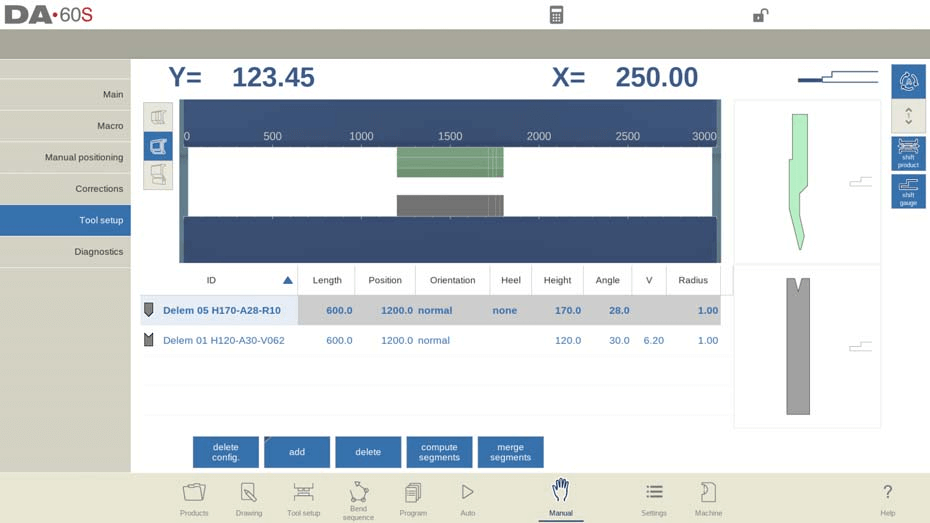
Configuración de herramientas
La configuración de herramientas en el modo manual del DELEM DA-66S es muy similar a la del modo automático. Aunque cada modo permite configuraciones distintas, puede optar por usar la configuración del modo automático en el modo manual, pero tenga cuidado con las diferentes configuraciones.
En el menú de configuración de herramientas del modo manual de la DELEM DA-66S, puede agregar, quitar o reposicionar fácilmente herramientas como punzones, matrices y adaptadores. Este proceso refleja las funciones principales de configuración de herramientas, lo que permite realizar ajustes personalizados para optimizar sus operaciones de plegado. Además, puede segmentar las herramientas al agregarlas, según sus necesidades específicas.
Cambiar producto

En el modo manual del DELEM DA-66S, la función "Desplazar producto" simplifica el desplazamiento del producto. Los puntos de ajuste ayudan a los usuarios a mover el producto con precisión, facilitando su alineación con el lateral de las herramientas o el centro de la estación.
Funciones clave para el posicionamiento del producto:
- Saltar a la izquierda: Cambie el producto a una combinación de herramientas diferente a la izquierda.
- Saltar a la derecha: Cambie el producto a una combinación de herramientas diferente a la derecha.
- Desplazamiento a la izquierda: Mueva el producto 1 milímetro hacia la izquierda dentro del mismo conjunto de herramientas.
- Desplazamiento a la derecha: Mueva el producto 1 milímetro hacia la derecha dentro del mismo conjunto de herramientas.
El uso de estas funciones en el modo manual del DELEM DA-66S garantiza un control preciso sobre el posicionamiento del producto, mejorando tanto la flexibilidad como la precisión en las operaciones.
Parámetros de programación y vistas
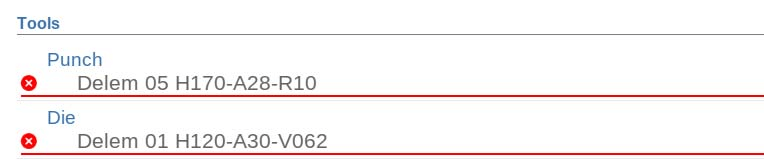
En el modo manual del DELEM DA-66S, puede programar parámetros individualmente, cada uno de los cuales se muestra junto con símbolos y colores de fondo para una fácil identificación.

Un símbolo de información indica un cambio debido a una entrada reciente, resaltando los ajustes realizados.

Un símbolo de estrella le avisa cuando un valor de parámetro difiere de los cálculos del control, lo cual resulta útil para configuraciones deliberadas o limitadas por restricciones.

Los errores se marcan con un símbolo de error si un valor es incompatible con el programa actual, como por ejemplo un dobladillo realizado sin las herramientas adecuadas.
El lado derecho de la pantalla proporciona acceso a múltiples vistas, incluidas Principal, Macro, Posicionamiento manual, Correcciones y Diagnósticos, mejorando el control del usuario y las capacidades de monitoreo en el Modo Manual del DELEM DA-66S.

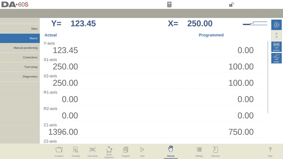
Macro
En el modo manual del DELEM DA-66S, la vista macro muestra valores de eje grandes en la pantalla, lo que facilita su lectura a distancia. Esta función es especialmente útil al trabajar a distancia desde el panel de control.
Ejecución de una operación de doblado segura y eficiente
Procedimientos de movimiento manual de ejes
Para mover los ejes manualmente de forma segura, utilice el volante del DELEM DA-66S. Asegúrese de que la máquina esté detenida al reposicionar los ejes auxiliares, mientras que el eje Y requiere que el sistema esté activo y se cumplan ciertas condiciones, como la función de ajuste.
Después de tocar Posicionamiento manual en la pantalla principal del Modo Manual, aparece la siguiente pantalla:
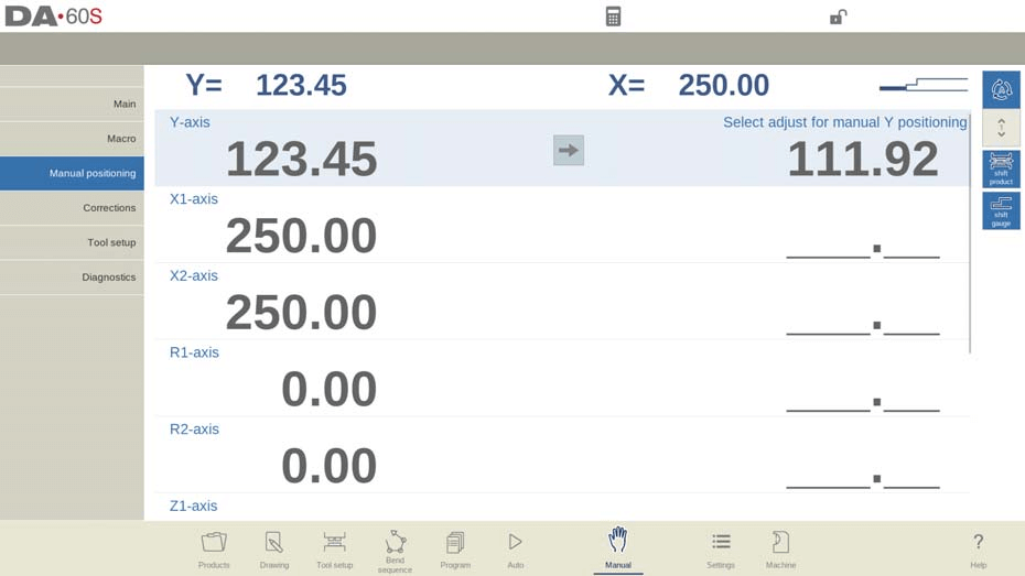
En el modo manual del DELEM DA-66S, puede mover los ejes manualmente con el volante. Los pasos varían según el tipo de eje que esté ajustando.
Para ejes auxiliaresAsegúrese de que la máquina esté detenida (el LED del botón de parada está encendido). Seleccione el eje del tope trasero que desea mover y utilice la rueda para reposicionarlo.
Con el Eje YEl posicionamiento manual es similar, pero requiere que la máquina esté encendida (el LED del botón de inicio debe estar encendido). Además, la función de ajuste debe estar activada (revise los mensajes en la esquina superior derecha si no lo está). Asegúrese de que el eje Y esté por debajo del punto de silencio y de que se haya introducido un comando de prensado en el CNC.
Siguiendo estos procedimientos en el modo manual del DELEM DA-66S, puede gestionar de forma segura y eficaz los ejes de la máquina.
Utilización del modo de enseñanza
Para enseñar eficazmente al control de modo manual DELEM DA-66S una posición detectada al ajustar manualmente un eje, siga este sencillo procedimiento. Utilice el volante para mover un eje a la posición deseada. Para guardar esta posición, toque el nombre del eje en la columna "Programado"; el valor real del eje de la izquierda se añadirá al campo del eje programado de la derecha.

Al regresar a la pantalla estándar del modo manual del DELEM DA-66S, encontrará el parámetro del eje actualizado con este valor recién enseñado.
Monitoreo y diagnóstico para operaciones seguras
Correcciones
En el modo manual del DELEM DA-66S, puede ver y verificar las correcciones de los pliegues en una sola línea, de forma similar al modo automático. Estas correcciones y las entradas en la base de datos de correcciones son cruciales para obtener resultados de pliegue precisos. El acceso a la base de datos le permite modificar y optimizar estas correcciones, lo que también puede ser útil en los procesos de prueba de pliegue.

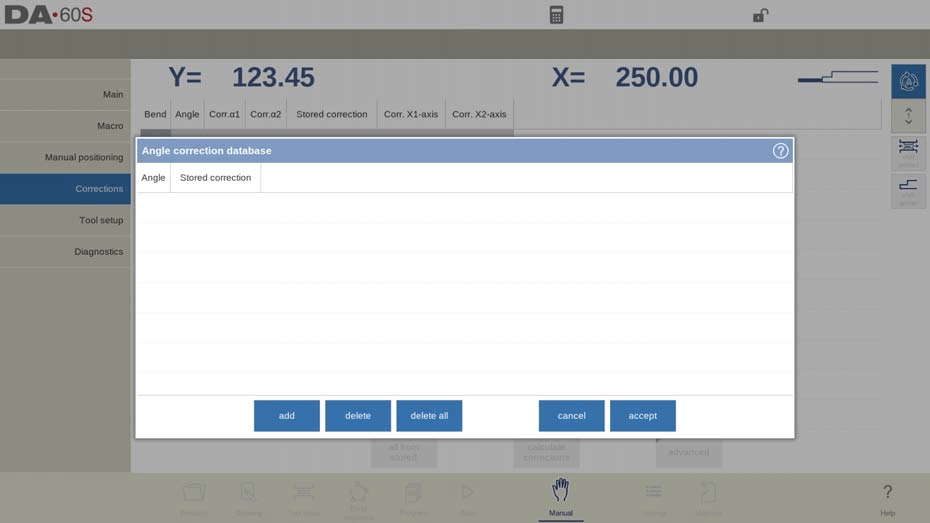
El Tolerancia de curvatura La función del modo manual del DELEM DA-66S permite introducir datos en la tabla de tolerancias de plegado. Al añadir solo las correcciones necesarias según los parámetros de plegado activos, se puede calcular la tolerancia de plegado a partir de la diferencia entre los valores programados y medidos. Para activar esta función, acceda al modo Ajustes.
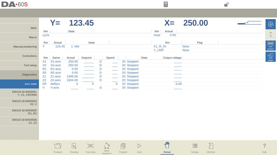
Diagnóstico y monitoreo en tiempo real
En el modo manual de la DELEM DA-66S, la función de diagnóstico proporciona una vista completa del estado de los ejes de la máquina. Esta función permite a los operadores supervisar el estado de cada eje en tiempo real durante un ciclo de plegado. Acceder a Diagnóstico le permite observar el comportamiento de los controles, lo que promueve operaciones eficientes y seguras.
Monitoreo del estado de E/S
El modo manual del DELEM DA-66S incluye una función de estado de E/S detallada que ofrece información sobre el estado actual de todas las entradas y salidas. Esta monitorización en tiempo real es crucial para evaluar el rendimiento de la máquina y solucionar rápidamente cualquier problema potencial durante las operaciones.

Vista de E/S ampliada
Para una mejor observación, la función de E/S con zoom del modo manual del DELEM DA-66S permite seleccionar hasta ocho pines para una vista ampliada. Esta función facilita la monitorización a distancia, garantizando un seguimiento sencillo de las entradas y salidas críticas.
Modo de prueba de flexión para precisión
El modo manual DELEM DA-66S incluye una función de prueba de doblado diseñada para ajustar sus operaciones de doblado.

Una vez activado, los ejes permanecen en sus posiciones de retracción tras el ciclo de plegado inicial, y el soporte de la pieza mantiene su ángulo si está habilitado. Este modo detiene cualquier cambio de paso.
Al finalizar el plegado de prueba, el eje Y se detiene en UDP, lo que permite a los operadores medir ángulos con precisión y aplicar las correcciones necesarias. Tras los ajustes, se puede repetir el plegado. El soporte de la pieza reanuda su movimiento siguiendo el eje Y al volver a su posición original. Esto garantiza correcciones precisas y una mayor precisión de plegado.
Preguntas frecuentes (FAQ)
¿Cómo puedo garantizar la seguridad al operar el modo manual del DELEM DA-66S?
Siga siempre las instrucciones de seguridad del fabricante, asegúrese de que la máquina esté correctamente calibrada y revise la posición de todos los ejes antes de comenzar cualquier operación. Es fundamental contar con el equipo de seguridad y la capacitación adecuados.
¿Cómo puedo mantener un rendimiento óptimo de mi DELEM DA-66S en modo manual?
El mantenimiento regular es fundamental. Revise la máquina cada 500 horas, inspeccione los componentes esenciales, limpie el sistema y lubrique las piezas móviles según las instrucciones del fabricante.
¿Cómo aplico correcciones al ángulo de curvatura en el modo manual del DELEM DA-66S?
Mida el ángulo actual después de una curva y ajuste los parámetros de Corr.α en modo manual. Esto le permite programar las correcciones necesarias y lograr los ángulos deseados con precisión.
¿Qué debo hacer si los ejes no vuelven a su posición original después de una prueba de flexión?
Después de la prueba de flexión, asegúrese de que el eje Y esté en el UDP. Si el soporte de la pieza no sigue, verifique que esté habilitado y compruebe si hay obstrucciones o desalineaciones en la configuración.
Conclusión
Para operar el DELEM DA-66S en modo manual de forma segura y eficiente, es necesario comprender sus características y realizar un mantenimiento regular. Seguir las pautas anteriores y abordar las incidencias más comunes puede mejorar el rendimiento y la vida útil de la máquina. Para obtener asistencia detallada o más información, contacte con nuestro equipo o acceda a la documentación en nuestro sitio web.


