


If you’re looking to harness the full potential of ESA S530 Integrated Cad for your drawing needs, you’re in the right spot. Understanding how to effectively draw using this powerful CAD software is crucial for streamlining your design process. I’ll guide you through the essential steps and techniques, ensuring you can maximize its capabilities. Whether you’re new to ESA S530 or aiming to refine your skills, this article will provide you with the insights necessary to enhance your design efficiency and creativity.
Wstęp
The ESA S530 Integrated CAD features a powerful numeric control function that allows you to draw essential graphic elements, such as the punch, die, and the workpiece to bend. Accessing the drawing function for these elements in the ESA S530 Integrated CAD is straightforward, and the process is detailed in the brief guide provided.
Funkcja rysowania
The drawing function in ESA S530 Integrated CAD works by plotting straight line segments depending on the data entered by the operator. In ESA S530 Integrated CAD, the data may only be entered in polar form.
Polar Entry of the Drawing Data
In the context of ESA S530 Integrated CAD, the polar entry of the drawing data is a crucial function that enables precise design creation. This feature facilitates the definition of lines by allowing users to input two critical data elements:
- length of the line;
- angle in relation to the next line.
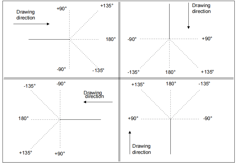
By utilizing ESA S530 Integrated CAD, the angles must be specified within a range of ±180.0°, providing flexibility and precision in design orientation. The conventions for inputting these angles ensure accuracy and consistency in the direction of the drawing, optimizing the efficiency of the design process.
Dane ogólne
When using the ESA S530 Integrated CAD system, before beginning to draw any graphic element, the operator must enter specific general data items.
These data items can vary depending on the type of object being drawn within the ESA S530 environment. Proper entry of this information is crucial as it sets the foundation for accurate and efficient design processes. The required data items for each phase of drawing are meticulously described in the chapters dedicated to each individual object within the ESA S530 Integrated CAD documentation.
Activation
To access the drawing, go to the [Potwierdzać] przycisk i naciśnij [WCHODZIĆ].
By ensuring all general data is entered correctly at the onset, users can fully leverage the robust features of ESA S530 Integrated CAD, thus enhancing both precision and workflow efficiency in their design projects.
Strona rysunku
In the ESA S530 Integrated CAD interface, the drawing page is designed with several intuitive windows to streamline your design experience:
- Area 1: This window is dedicated to the graphic plotting of your drawing. It visually represents the drawing based on the data you’ve entered, allowing you to see real-time updates and adjustments as you work within the ESA S530 Integrated CAD system.
- Area 2: Here, you’ll find the polar drawing entry interface. This window facilitates precise input for the length of the line to be drawn (“ja“) and the angle in relation to the subsequent line (“alfa“). Such detailed entry ensures accuracy and cohesion in your design elements.
- Area 3: This window offers a dynamic display of the image of the element currently being drawn. It provides an ongoing visual reference, aiding you in maintaining consistency and precision throughout your project.

Each of these areas within the ESA S530 Integrated CAD environment is tailored to enhance your design efficiency, ensuring that every project is crafted with the utmost accuracy and ease.
Drawing Data Entry
When using the ESA S530 Integrated CAD, the first line of standard length is plotted upon accessing the drawing in Area 1. This line is conveniently highlighted by a circle, making it easy to identify. If you need to adjust the initial direction of the drawing, simply press one of the directional arrows available in the interface.
In Area 2, the cursor defaults to field “ja”, which contains a standard value that you can modify as needed. It’s important to note that each data item you enter in the ESA S530 Integrated CAD must be confirmed with the [WCHODZIĆ] key to ensure accuracy and proper processing.
How to Enter a Drawing in the Polar Mode
As described in the “Polar entry of the drawing data” chapter, the values to enter are:
1) the length of the line. The line is rescaled depending on the length entered and the cursor moves to the “alfa” angle entry field;
2) the angle in relation to the next line.
A circle indicating which line is being drawn makes the drawing easier to do. Once the entry has been made, the cursor moves to field “ja”, where the length of the new line is entered. Entry of this pair of data items must be repeated until the drawing is completed.
How to Update the Information in the Drawing
To update the information in your drawing using ESA S530 Integrated CAD, simply adjust the measurements as needed. The software automatically rescales the drawing if the measurements exceed the window size, ensuring optimal display and accuracy.
How to Terminate the Drawing
Enter zero for the angle of the last line to indicate that the drawing has terminated.
How to Select the Drawing Data
To select the drawing data, scroll through them with the

I

Key
scrolls backwards through the data that form the drawing in the sequential mode, passing between the “alfa” field and the “ja” field each time.
Key
scrolls forwards through the data in the sequential mode, passing through the “ja” field each time.
The line relative to the displayed data is highlighted when the data of a drawing are scrolled.
How to Modify the Data of a Drawing
Proceed in the following way to modify the data of a drawing:
- Select the data item;
- Enter the new value;
- Naciskać [WCHODZIĆ] to confirm the new data item;
The drawing will be plotted again to suit the new data item entered.
Use of the Arrows and Direction Keys
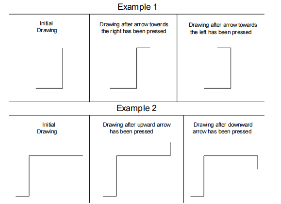
In ESA S530 Integrated CAD, you can efficiently utilize the arrows and direction keys to streamline your drawing process. These keys allow you to automatically set the angle of a line in relation to the next, greatly enhancing precision. By pressing an arrow key, you can instantly plot a new segment that aligns with the specific direction of the key pressed.
The direction keys are: [Home], [PgUp], [PgDn], [End] and they are near the arrows.

The arrows position the segment horizontally or vertically.
The direction keys position the segment diagonally.
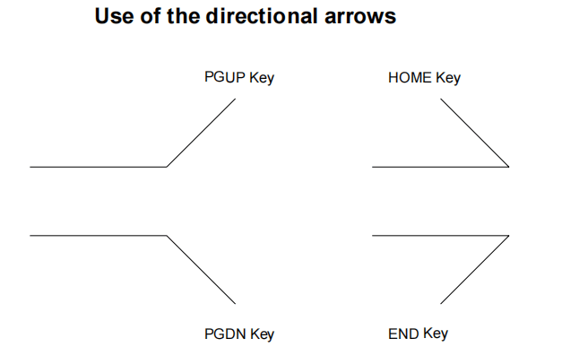
The angle between the current line and the segment plotted in accordance with the direction key pressed, is automatically entered in the “alfa“ field.
This angle must be confirmed with the [WCHODZIĆ] key if the length of the new line must be entered.
How to Cancel a Drawing Line
To cancel a drawing line, first select the line to be cancelled and then press the

key.
The current line will be cancelled. The successive lines will be positioned in accordance with the angle entered in the line preceding the one that is cancelled.
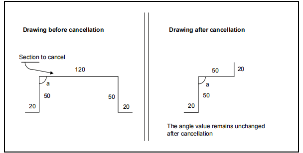
If the last line entered is cancelled, it will be substituted by a line of standard length. To eliminate this line as well, go to the data of the preceding line and terminate the drawing.
Często zadawane pytania (FAQ)
How can I draw precise angles using ESA S530 Integrated CAD?
To draw precise angles in ESA S530 Integrated CAD, utilize the arrows and direction keys. These features allow you to automatically enter angles in the “alfa” field for accurate line placement and direction.
What should I do if my segments are not aligning correctly with ESA S530 Integrated CAD?
Ensure you are using the correct keys for segment alignment. Arrows should be used for horizontal or vertical positioning, while direction keys like [Home], [PgUp], [PgDn], and [End] help position segments diagonally.
How do I confirm a line length in ESA S530 Integrated CAD after setting an angle?
After setting your desired angle with the direction keys, confirm and enter the length of the new line by pressing the [ENTER] key. This will lock in the segment details within ESA S530 Integrated CAD.
Wniosek
In conclusion, mastering the art of drawing with ESA S530 Integrated CAD involves understanding how to effectively use tools like the arrows and direction keys to achieve precise line positioning. By incorporating these techniques, you’ll be able to enhance your design accuracy and efficiency within the software. If you’re ready to take your skills to the next level, consider exploring additional resources or contacting our team for further assistance and insights.


