


W świecie precyzyjnej obróbki metali skuteczne programowanie systemów stempli i matryc w trybie maszynowym DELEM DA-69T ma kluczowe znaczenie dla uzyskania dokładnych i wydajnych rezultatów. Jeśli szukasz wskazówek, jak programować stemple i matryce w trybie maszynowym DELEM DA-69T, jesteś we właściwym miejscu.
Niniejsza dokumentacja przeprowadzi Cię przez podstawowe kroki i wskazówki dotyczące programowania stempli i matryc, specjalnie dostosowane do interfejsu DELEM DA-69T. Niezależnie od tego, czy dopiero zaczynasz korzystać z tego trybu maszyny, czy chcesz udoskonalić swoje umiejętności programowania, ten przewodnik pomoże Ci osiągnąć precyzję i wydajność w projektach obróbki metali. Przyjrzyjmy się szczegółom i pomożemy Ci wykorzystać pełen potencjał trybu maszyny DELEM DA-69T.
Przegląd programowania Punch
W tej zakładce można zaprogramować stemple używane w maszynie. Można dodawać nowe stemple, edytować i usuwać istniejące.
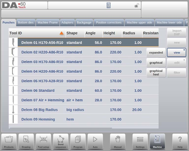
Na stronie głównej wyświetlana jest lista dostępnych wykrojników. Korzystając z funkcji Widok, podobnej do trybu Produkty, można wybrać różne widoki. Oprócz domyślnego widoku Rozszerzonego dostępne są również Widok Graficzny i Widok Graficzny Pięty.
Katalog graficzny
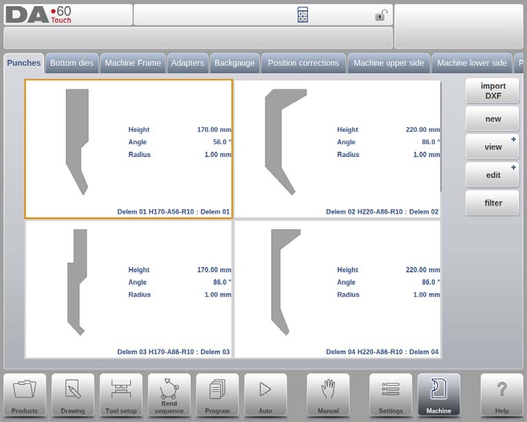
W wersji graficznej prezentowana jest geometria narzędzi oraz ich główne właściwości.
Katalog graficzny uderza piętami
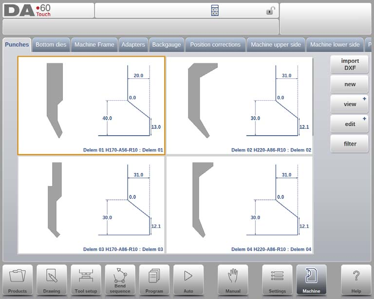
W programie Graphical Heel wyświetlana jest geometria narzędzi oraz właściwości pięty.
Utwórz nowy cios
Krok 1: Tworzenie nowego stempla
Aby utworzyć nowy stempel, naciśnij przycisk „Nowy” w bibliotece. Rozpocznie to proces definiowania profilu stempla z wykorzystaniem funkcji programowania i rysowania w trybie maszynowym DELEM DA-69T.

Krok 2: Programowanie podstawowego kształtu i identyfikatora
- Kształt: Wybierz podstawowy kształt stempla odpowiadający żądanej akcji. Dostępne opcje obejmują:
- Standardowy dziurkacz:Służy do gięcia w powietrzu i podstawowego dobijania.
- Dziurkacz do zaginania krawędzi:Ma płaski spód umożliwiający wykonanie specyficznych zagięć dołu.
- Powietrze + dziurkacz do zagięcia krawędzi: Nadaje się do normalnych zgięć powietrza i funkcji podwijania.
- Duży cios promieniowy:Zaprojektowane do gięcia o dużym promieniu.
- ID: Przypisz unikalną nazwę lub numer, nieprzekraczający 25 znaków, aby zidentyfikować narzędzie. Może to obejmować znaki alfanumeryczne. Po zakończeniu kliknij „Akceptuj”, aby przejść do parametrów danych narzędzia.
Krok 3: Definiowanie parametrów danych narzędzia
Po wprowadzeniu kształtu i identyfikatora, tryb maszyny DELEM DA-69T wyświetli okno dialogowe umożliwiające wprowadzenie początkowych wymiarów i właściwości narzędzia. Konkretne parametry będą się różnić w zależności od wcześniej wybranego kształtu stempla.
Krok 4: Opcjonalny import DXF
Dla większej wygody, kształt stempla można również zaimportować za pomocą opcjonalnej funkcji importu DXF. Funkcja ta jest standardem w trybie maszyny DELEM DA-69T, oferując efektywny sposób na wprowadzanie skomplikowanych wzorów.
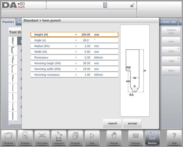
Standardowy dziurkacz

- Wysokość: Niezbędne do obliczenia głębokości gięcia. Wprowadź dane poprawnie.
- Kąt:Ustaw kąt końcówki dziurkacza tak, aby odpowiadał potrzebom gięcia.
- Promień:Promień końcówki dziurkacza powinien być większy od powstałego promienia gięcia.
- Szerokość:Określ szerokość narzędzia w celu precyzyjnego programowania.
- Opór:Określ maksymalną siłę nacisku narzędzia.
Rysowanie orientacji stempla na ekranie
Prawa strona narzędzia to strona tylnego zderzaka. Dolny punkt stempla będzie umieszczony na linii środkowej kształtu prasy krawędziowej.
Rysowanie i konfigurowanie dziurkacza
- Rysunek: Używaj kątów i długości linii do rysowania narzędzi. Używaj narzędzi dotykowych podobnych do tych używanych do rysowania produktów.
- Punkt montowania (opcjonalnie programowalny): Oznacza punkt połączenia na belce prasy, dostępny w konfiguracji normalnej i toczonej.
Funkcje rysowania
- Usuń linię:Usuń niechciane segmenty.
- Automatyczne wykończenie:Automatycznie uzupełnij zarys narzędzia.
- Zresetuj/Przeładuj rysunek:Powrót do podstawowego kształtu dla nowych lub istniejących dziurkaczy.
- Właściwości:Modyfikuj atrybuty linii i przypisz powierzchnie obszycia.
- Właściwości narzędzia:Aktualizacja danych i opisów narzędzi.

Dodatkowe parametry
- Opis:Edytowalna, zwięzła nazwa narzędzia.
- Opór: Ustawia maksymalną dopuszczalną siłę.
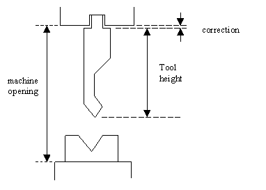
- Typ wsparcia: Wybierz montaż na 'głowie' lub 'ramieniu', aby uzyskać dokładność osi Y. 0 = montaż na ramieniu (ustawienie domyślne), 1 = montaż na głowie.
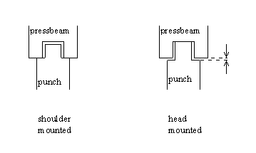
W przypadku wybrania opcji „montaż na ramieniu” położenie osi Y jest obliczane na podstawie standardowej wysokości narzędzia. Jest to ustawienie domyślne. W przypadku wybrania opcji „montaż na głowicy” dokonywana jest korekta obliczenia osi Y.
4. Preferowany:Oznacz narzędzia do preferowanego wyboru w procesach zautomatyzowanych.
5. Domyślny adapter:Ustaw najczęściej używane adaptery na automatyczne ładowanie.
6. Wymiary obcasa:Określ szerokość, wysokość i promień pięty bez wpływu na całkowitą wysokość narzędzia.
Edycja rysunków dziurkacza
Wybierz i edytuj narzędzia z biblioteki, korzystając z dostępnych funkcji rysowania. Narzędzie pojawia się na ekranie i można je edytować za pomocą funkcji rysowania.
Dziurkacz do zaginania krawędzi

Aby skutecznie programować w trybie maszyny DELEM DA-69T, należy dokładnie skonfigurować parametry dziurkarki do zaginania krawędzi w następujący sposób:
1. Wysokość:Wprowadź dokładnie całkowitą wysokość narzędzia, ponieważ jest to niezbędne do obliczenia głębokości gięcia.
2. Szerokość podwinięcia:Wprowadź szerokość narzędzia, aby określić powierzchnię styku z materiałem.
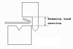
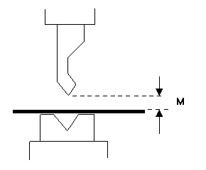
3. Otwór załadunkowy z podwijaniem: Zaprogramuj pozycję otwarcia dziurkacza, biorąc pod uwagę dwukrotnie większą grubość arkusza, aby zapewnić prawidłowe umiejscowienie obszycia.
4. Odporność na obszywanie:Ustaw maksymalną siłę, jaką narzędzie może wytrzymać podczas zaginania, aby chronić jego integralność.
Po wprowadzeniu tych wartości utwórz rysunek narzędzia, określając kąt i długość linii, w razie potrzeby korzystając z narzędzi do rysowania dotykowego, podobnie jak ma to miejsce w przypadku projektowania produktów.
Powietrze + dziurkacz do zaginania krawędzi
- Wysokość:Wprowadź całkowitą wysokość narzędzia, aby dokładnie określić głębokość gięcia.
- Kąt: Ustaw kąt końcówki dziurkacza, aby uzyskać pożądane efekty gięcia.
- Promień:Użyj promienia końcówki dziurkacza jako wewnętrznego promienia gięcia, jeśli jest on większy od obliczonego promienia wewnętrznego.
- Szerokość:Określ szerokość narzędzia, aby zapewnić prawidłowe wyrównanie.
- Opór:Ustal maksymalną siłę, jaką można użyć przy używaniu narzędzia, aby zapewnić bezpieczne użytkowanie.
- Wysokość podwinięcia:Ustaw wysokość dziurkacza w celu jego ruchu w dół podczas obszywania.
- Szerokość podwinięcia:Wprowadź szerokość części dziurkowanej mającej kontakt z produktem.
- Odporność na obszywanie:Określ maksymalną siłę potrzebną do użycia narzędzia podczas zaginania, aby zapobiec przeciążeniu.
- Otwór załadunkowy z podwijaniem: Zaprogramuj pozycję otwarcia dziurkacza, biorąc pod uwagę ilość wprowadzanego produktu i grubość arkusza.
Tworzenie rysunków narzędzi
Wykorzystaj funkcje rysowania DELEM DA-69T do tworzenia profili narzędzi. Wprowadź niezbędne wartości kąta i długości linii, korzystając w razie potrzeby z narzędzi rysowania dotykowego. Dostępne są również narzędzia rysowania dotykowego, podobnie jak w przypadku metody rysowania produktu.

Duży promień uderzenia
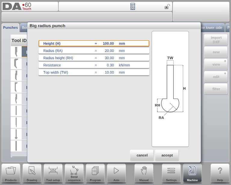
- Wysokość:Wprowadź całkowitą wysokość narzędzia, aby obliczyć prawidłową głębokość gięcia.
- Promień:Określ promień końcówki stempla, aby umożliwić precyzyjne gięcie.
- Wysokość promienia:Wskaż wysokość większej części promienia narzędzia, jak pokazano na rysunku maszyny.
- Opór:Ustaw maksymalną dopuszczalną siłę na narzędziu, aby zapobiec przeciążeniu.
- Szerokość górna:Określ szerokość górnej części stempla, aby zapewnić prawidłowe dopasowanie narzędzia.
Po wprowadzeniu tych wartości użyj narzędzi rysunkowych maszyny, aby utworzyć profil narzędzia, wprowadzając wartości kąta i długości linii. Dostępne są narzędzia rysowania dotykowego, podobne do metod rysowania produktów.
Programowanie matryc dolnych
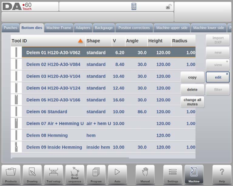
W tej zakładce można zaprogramować dolne matryce używane w maszynie. Można dodawać nowe matryce, edytować istniejące, a także je usuwać.

Na stronie głównej wyświetlana jest lista dostępnych wykrojników. Korzystając z funkcji Widok, podobnej do trybu Produkty, można wybrać różne widoki. Oprócz domyślnego widoku Rozszerzonego, dostępny jest również widok Graficzny.
Katalog graficzny
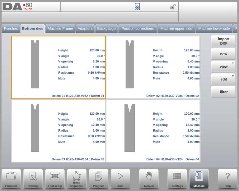
W wersji graficznej prezentowana jest geometria narzędzi oraz ich główne właściwości.
Aby zaprogramować nową kostkę, naciśnij przycisk Edytuj w bibliotece, a następnie wybierz opcję Nowy.
Utwórz nową kostkę
Krok 1: Tworzenie nowej kostki
Aby utworzyć nową matrycę, należy najpierw kliknąć „Nowości” w bibliotece matryc. Ta czynność inicjuje proces definiowania profilu matrycy z wykorzystaniem funkcji programowania i rysowania w trybie maszynowym DELEM DA-69T.
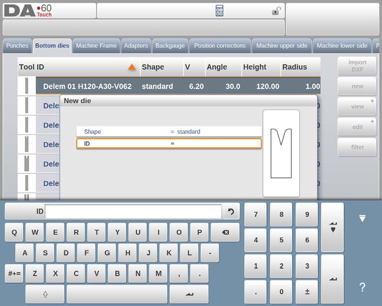
Krok 2: Programowanie podstawowego kształtu i identyfikatora
Kształt: Wybierz podstawowy kształt matrycy odpowiadający żądanej akcji. Dostępne opcje w trybie maszynowym DELEM DA-69T obejmują:
- Standardowa kostka:Służy do gięcia w powietrzu i podstawowego dobijania.
- Wykrojnik Hem Bend: Posiada płaską końcówkę umożliwiającą wykonanie specyficznych zagięć podwinięcia.
- Wykrojnik do zagięcia wewnętrznego brzegu: Nadaje się do gięcia w powietrzu i podwijania.
- Air + Hem Bend U Die:Zaprojektowane do gięcia w powietrzu ze szczególnymi funkcjami podwinięcia.
- Matryca Multi-V: Posiada liczne otwory w kształcie litery V i/lub U.
- Die Vario-V: Oferuje zmienne otwory w kształcie litery V lub U (dostępne, jeśli obecny jest system Vario-V).
- Wykrojnik do zaginania krawędzi wewnętrznej Multi-V:Zawiera liczne otwory w kształcie litery V lub U ze zintegrowanym systemem podwijania.
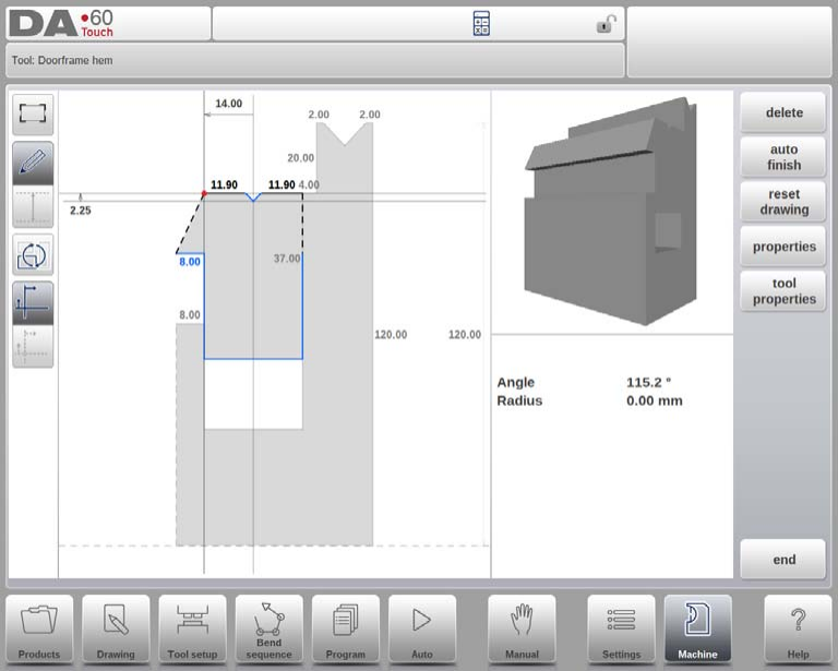
- Wykrojnik do zaginania krawędzi ościeżnicy:Wykrojnik w kształcie litery V z oddzielną funkcją wewnętrznego podwijania do produkcji ościeżnic drzwiowych.
- Die Wingbend:Zawiera segmenty promienia obrotowego do zastosowań specjalnych.
ID: Przypisz unikalną nazwę lub numer identyfikujący narzędzie, nieprzekraczający 25 znaków. Identyfikator może zawierać znaki alfanumeryczne. Po zakończeniu kliknij „Akceptuj”, aby przejść do parametrów danych narzędzia.
Krok 3: Definiowanie parametrów danych narzędzia
Po wprowadzeniu kształtu i identyfikatora, tryb maszyny DELEM DA-69T wyświetli okno dialogowe z prośbą o wprowadzenie początkowych wymiarów i właściwości narzędzia. Konkretne parametry będą się różnić w zależności od wybranego kształtu matrycy.
Krok 4: Import DXF (fakultatywny)
Dla większej wygody w trybie maszynowym DELEM DA-69T, kształt wykrojnika można również zaimportować za pomocą opcjonalnej funkcji importu DXF. Funkcja ta jest dostępna standardowo i stanowi wydajny sposób na wprowadzanie skomplikowanych projektów.
Standardowa kostka

- Szerokość:To jest szerokość narzędzia, które ma zostać zaprogramowane w trybie maszynowym DELEM DA-69T.
- Wysokość:Określa całkowitą wysokość narzędzia, która jest niezbędna do dokładnego obliczenia głębokości gięcia.
- Promień:Odnosi się do promienia krawędzi przy otworze V matrycy.
- Kąt V:Oznacza kąt matrycy, który będzie miał wpływ na operację gięcia.
- Otwarcie V:Rzeczywisty wymiar otworu w kształcie litery V, gdzie szerokość V to odległość między przecinającymi się liniami.
- Opcje dolne V:
- Standard:Ostry kąt u dołu.
- Okrągły:Dół matrycy z promieniem ustawionym za pomocą opcji 'Promień wewnętrzny'.
- Płaski:Płaskie dno matrycy o określonym wymiarze poprzez „Szerokość dna”.
- Opór:Maksymalna siła dopuszczalna dla narzędzia.
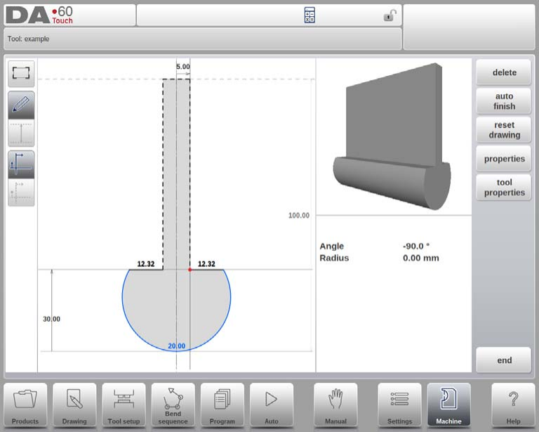
Orientacja rysunku i Punkt montowania (opcjonalnie programowalny)
W trybie maszyny DELEM DA-69T prawa strona matrycy jest wyrównana z tylnym zderzakiem. Środkowe położenie otworu w kształcie litery V pokrywa się ze środkiem kształtu prasy krawędziowej. Po wprowadzeniu standardowych wymiarów, narzędzia są rysowane z wykorzystaniem wartości kąta i długości linii, z opcjonalnymi funkcjami rysowania.

Punkt mocowania matrycy, oznaczony na rysunku trójkątną strzałką, wskazuje miejsce, w którym matryca łączy się ze stołem lub adapterem. Dostępne są oddzielne punkty mocowania dla orientacji normalnej i obróconej. Funkcja ta jest dostępna zarówno w adapterach, jak i w stole. Jeśli ta funkcja nie jest włączona, wskaźniki nie będą wyświetlane.
Funkcje rysowania
Podczas rysowania dostępne są różne funkcje:
- Usuń linię:Usuwa segment linii z rysunku.
- Zmień wysokość: Dostosowuje pomiar wysokości narzędzia.
- Automatyczne wykończenie:Automatycznie uzupełnia zarys narzędzia.
- Zresetuj rysunek: Przywraca początkowy kształt narzędzia dla nowej matrycy.
- Przeładuj rysunek:Powraca do podstawowego kształtu istniejących matryc.
Właściwości narzędzia

Właściwości narzędzia można dostosować w następujący sposób:
- Właściwości:Modyfikuj parametry linii lub kąta, dodaj/usuń promień i wyznacz powierzchnie obróbkowe.
- Opis narzędzia: Przypisz lub edytuj nazwę opisową składającą się z maksymalnie 25 znaków.
- Opór:Ustaw maksymalną siłę nacisku narzędzia.
- Niemy: Określ odległość wyciszenia przy zmianach prędkości.
- Preferowany:Oznacz narzędzia jako preferowane do automatycznego wyboru.
- Domyślny adapter: Ustaw domyślne adaptery dla typowych kombinacji narzędzie-adapter.
Edycja rysunku wykrojnika
Aby zmodyfikować istniejące narzędzie w trybie maszynowym DELEM DA-69T, wybierz narzędzie z biblioteki i skorzystaj z funkcji rysowania, aby wprowadzić zmiany.
Wykrojnik do zagięcia krawędzi
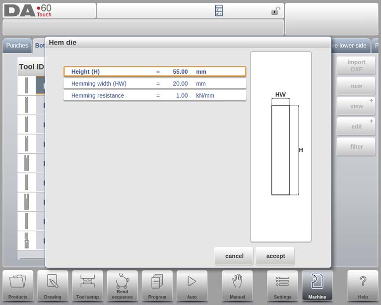
- Wysokość:Jest to całkowita wysokość narzędzia, która ma kluczowe znaczenie przy obliczaniu głębokości gięcia.
- Szerokość podwinięcia:Szerokość narzędzia, które wymaga zaprogramowania.
- Odporność na obszywanie:Maksymalna dopuszczalna siła nacisku na narzędzie podczas zakańczania, zapobiegająca uszkodzeniom.
Po wprowadzeniu tych wartości można utworzyć rysunek narzędzia, korzystając z funkcji rysowania DELEM DA-69T. Wymaga to wprowadzenia kątów i długości linii, a dostępne narzędzia do rysowania dotykowego ułatwiają ten proces.

Wykrojnik do zagięcia wewnętrznego brzegu
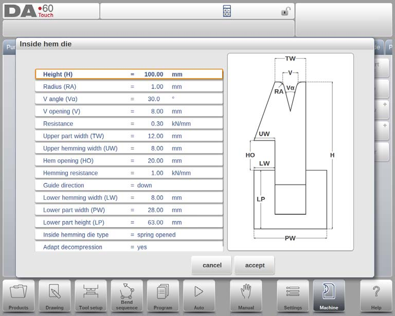
- Wysokość:Reprezentuje całkowitą wysokość narzędzia, mającą kluczowe znaczenie dla obliczenia głębokości gięcia.
- Promień: Definiuje promień krawędzi otworu w kształcie litery V.
- Kąt V:Określa kąt matrycy.
- Otwarcie V:Oznacza rozmiar otworu w kształcie litery V.
- Dół V:Opcje dla dolnej części otworu w kształcie litery V:
- „Standard”: Ostry kąt u dołu.
- 'Okrągły': Spód matrycy z promieniem, regulowany za pomocą 'Promienia wewnętrznego'.
- 'Płaskie': Płaskie dno dostosowane za pomocą opcji 'Szerokość dna'.
- Opór:Maksymalna dopuszczalna siła nacisku na narzędzie.
- Szerokość górnej części:Szerokość górnej części kostki.
- Szerokość górnego obszycia:Szerokość używana do obszywania górnej części.
- Otwarcie dołu: Wysokość matrycy po otwarciu w celu umieszczenia produktu.
- Odporność na obszywanie:Maksymalna siła podczas obszywania.
- Kierunek przewodnika:Definiuje konstrukcję mechaniczną.
- Szerokość dolnego obszycia:Szerokość segmentu podwijającego w dolnej części.
- Szerokość dolnej części:Szerokość dolnej części.
- Wysokość dolnej części:Wysokość dolnej części.
15. Typy matryc do zawijania wewnętrznego:
- Wiosna otwarta:
- Początkowa pozycja jest uniesiona dzięki wewnętrznej sprężynie.
- Prebenda:Arkusz kładzie się na wierzchu otwartej matrycy.
- Hem-Bend: Wstępnie wygięty produkt umieszczany w otworze podwinięcia; przy obliczaniu głębokości uwzględniana jest grubość blachy.
- Otwarte i zamknięte:
- Zablokowane domyślnie w wysokiej pozycji, do odblokowania w celu podwinięcia potrzebny jest mechanizm.
- Normalnie zamknięty:
- Rozpoczyna się w niskiej pozycji i wymaga aktywacji w celu wykonania czynności obszywania.
16. Adaptacja dekompresji
- Opcje:
- „nie”: Wartość otwarcia podwinięcia nie jest dodawana.
- „tak”: Dodano zarówno dla zagięć powietrznych, jak i zagięć rąbkowych.
- „air bend”: Dodano wyłącznie dla air bendów.
Rysowanie narzędzi i importowanie plików DXF (fakultatywny)

Po wprowadzeniu wartości możesz utworzyć rysunki narzędzi, podając kąt i długość linii, lub skorzystać z funkcji importu DXF. Upewnij się, że korpus matrycy znajduje się na warstwie 0, a ruchome części na innej warstwie o nazwie „wewnętrzny brzeg”, aby automatycznie wybrać typ narzędzia.
Air + hem bend U die
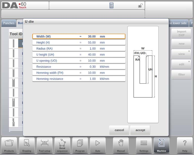
- Szerokość:Zmierz i wprowadź szerokość narzędzia.
- Wysokość:Wprowadź całkowitą wysokość, niezbędną do obliczenia głębokości gięcia.
- Promień: Określ promień krawędzi otworu w kształcie litery U, aby uzyskać gładkie zagięcia.
- Wysokość U:Określ wysokość otworu w kształcie litery U, aby ustalić głębokość gięcia.
- Otwór w kształcie litery U:Wprowadź szerokość otworu w kształcie litery U, aby spełnić wymagania materiałowe.
- Opór:Ustaw maksymalną dopuszczalną siłę nacisku na narzędzie.
- Szerokość podwinięcia:Zmierz szerokość przodu, aby zapewnić odpowiednie podszycie.
- Odporność na obszywanie:Ustal limit siły podczas podwijania.
Po wprowadzeniu tych wartości, skorzystaj z funkcji rysowania, aby utworzyć profil narzędzia, określając kąt i długość linii. Tryb maszynowy DELEM DA-69T oferuje również narzędzia do rysowania dotykowego, ułatwiające projektowanie precyzyjnych profili.

Matryca Multi V
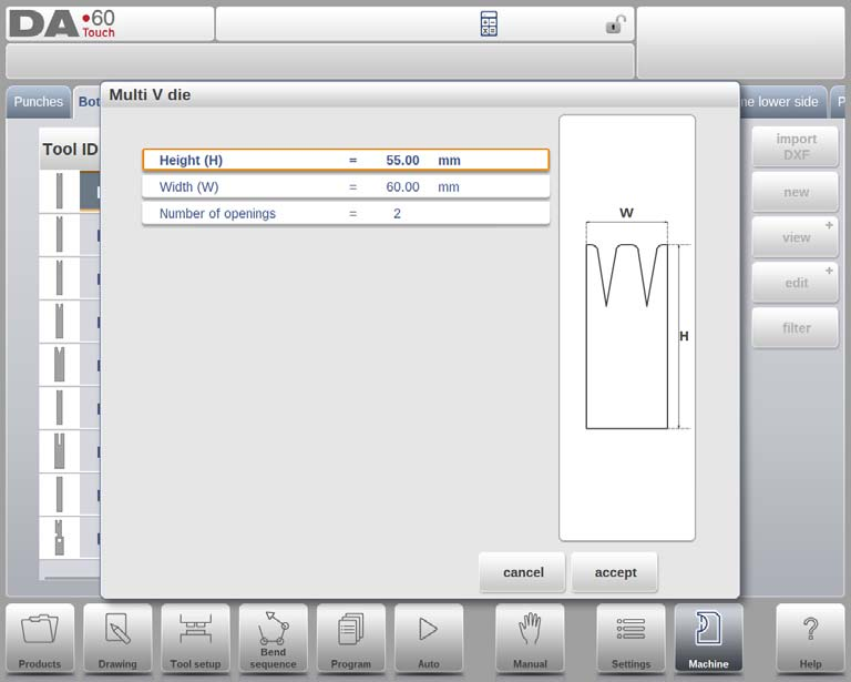
- Wysokość:Wprowadź całkowitą wysokość narzędzia, ponieważ jest ona kluczowa dla dokładnego obliczenia głębokości gięcia w trybie maszyny DELEM DA-69T.
- Szerokość:Określ szerokość narzędzia, aby zapewnić właściwe ustawienie i przyłożenie siły podczas operacji gięcia.
- Liczba otworów:Wprowadź liczbę otworów V lub U na narzędziu, aby dokładnie skonfigurować maszynę.
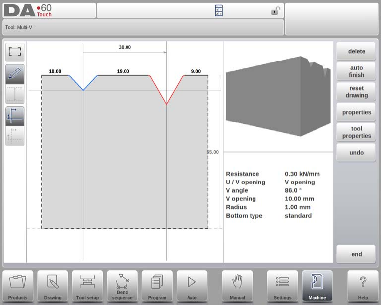
Właściwości otworu U/V
- Otwieranie właściwości: Zaprogramuj określone właściwości każdego otworu V lub U w sekcji „Właściwości” interfejsu trybu maszynowego DELEM DA-69T.
- Odporność na narzędzia: Wybierz, czy chcesz zaprogramować ogólny opór narzędzia czy też opór dla każdego otworu osobno, aby uzyskać precyzyjną kontrolę podczas procesu gięcia.

1. Otwór U/V: Wybierz pomiędzy otworami w kształcie litery U lub V, co określi rodzaj gięcia, jaki wykona Twoja maszyna DELEM DA-69T.
2. Promień:Ustaw promień krawędzi otworu w kształcie litery V, aby wpłynąć na kąt gięcia i przepływ materiału.
3. Kąt V:Zaprogramuj kąt matrycy, aby uzyskać żądaną precyzję i ostrość gięcia.
4. Otwarcie V:Wprowadź rozmiar otworu V, aby dopasować go do grubości materiału i potrzeb gięcia.
5. Dół V: Wybierz z:
- Standard:Ostry kąt dolny.
- Okrągły: Dół z określonym 'Promieniem wewnętrznym'.
- Płaski:Dół z określoną 'Szerokością dołu.'
6. Opór: Określ maksymalną dopuszczalną siłę dla każdego otworu w kształcie litery V lub U. Użyj wartości domyślnej, jeśli ma to zastosowanie do wszystkich narzędzi.
Rysunek narzędzi
Wprowadź kąt i długość linii za pomocą narzędzi rysunkowych DELEM DA-69T Machine Mode, aby tworzyć dokładne profile narzędzi. Dostępne są również narzędzia rysunkowe Touch, podobnie jak w przypadku metody rysowania produktów.
Matryca Vario V (dostępna tylko w przypadku obecności systemu Vario-V)

- Otwór U/V: Dokonaj wyboru w oparciu o swoje potrzeby w zakresie gięcia, korzystając z systemu Vario-V.
- Wysokość: Wprowadź całkowitą wysokość narzędzia niezbędną do obliczenia głębokości gięcia.
- Szerokość matrycy i kąt V: Wprowadź połowę szerokości i połowę kąta, aby umożliwić precyzyjną konfigurację narzędzia.
- Promień: Zdefiniuj promień krawędzi otworu.
- Wysokość i szerokość dołu: Określ wymiary w celu dokładnej konfiguracji matrycy.
Po wprowadzeniu tych typowych wartości można utworzyć rysunek narzędzia, korzystając z funkcji rysowania.

Właściwości narzędzia
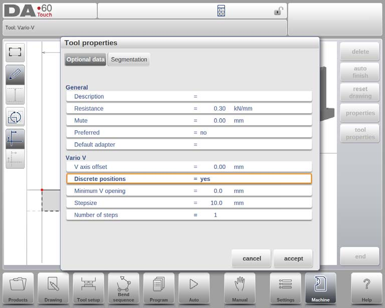
- Opis: Nadaj narzędziu zwięzłą nazwę, umożliwiającą identyfikację biblioteki.
- Opór i wyciszenie: Ustaw maksymalne limity siły i odległość wyciszenia powyżej arkusza.
- Przesunięcie osi V i pozycje dyskretne: Zarządzaj pozycjonowaniem i odstępami między otwarciami V.
- Minimalny otwór V, rozmiar stopnia, liczba stopni: Zdefiniuj parametry otwierania dla poszczególnych pozycji.
Import DXF (opcjonalnie)
Użyj funkcji importu DXF z dolnym korpusem matrycy na warstwie 0. Upewnij się, że ruchome części znajdują się na osobnej warstwie o nazwie „vario V”, aby umożliwić automatyczne rozpoznanie.
Wykrojnik Multi-V do wewnętrznej krawędzi

- Wysokość (H): Całkowita wysokość narzędzia do obliczenia głębokości gięcia.
- Szerokość górnej części (TW): Szerokość górnej części kostki.
- Liczba otwarć: Otwory w narzędziu w kształcie litery V lub U.
- Kąt rąbka (Ha): Kąt jednostki podwijającej.
- Szerokość górnego obszycia (UW): Szerokość segmentu do obszycia górnej części.
- Otwarcie dołu (HO): Wysokość matrycy po otwarciu, umożliwiająca wykonanie zagięć brzegowych.
- Odporność na obszywanie: Maksymalna siła podczas obszywania.
- Szerokość dolnego podwinięcia (LW): Szerokość segmentu do obszycia dolnej części.
- Szerokość dolnej części (PW) i wysokość (LP): Wymiary dolnej części kostki.
- Typy matryc do zawijania wewnętrznego
- Otwarcie wiosny: Wykorzystuje sprężynę do wstępnego gięcia i gięcia krawędzi.
- Otwarte i zamknięte: Wysoka pozycja blokady do standardowego gięcia; odblokowana do podwijania.
- Normalnie zamknięte: Pozycja zamknięta, wymaga aktywacji w celu podwinięcia.
- Adaptacja dekompresji: Opcje dodawania wartości otwarcia podwinięcia do dekompresji. Dostępne opcje to: „nie” (nie dodano), „tak” (dodano zarówno dla zagięć powietrznych, jak i podwinięcia) lub „zagięcie powietrzne” (dodano tylko dla zagięć powietrznych).
Właściwości otwarcia U/V
Zdefiniuj cechy narzędzia dla każdego otworu V lub U w obszarze Właściwości. Opór narzędzia można ustawić ogólnie lub szczegółowo.
- Otwór U/V:Rodzaj otworu.
- Promień: Promień krawędzi otworu w kształcie litery V.
- Kąt V:Kąt kostki.
- Otwarcie V:Rozmiar otworu w kształcie litery V.
- Dół V:
- „Standard”: Ostry kąt.
- 'Okrągły': Dół z programowalnym promieniem ('Promień wewnętrzny').
- 'Płaskie': Płaskie dno o ustalonym wymiarze ('Szerokość dna').
- Opór: Maksymalna siła dla tego otwarcia; jeśli jednolita, pozostaw puste, ponieważ Właściwości narzędzia wystarczą.

Po wprowadzeniu wartości, utwórz rysunki narzędzi, używając kątów i długości linii, korzystając z narzędzi rysowania dotykowego i opcjonalnego importu DXF. DA-69T obsługuje tę funkcję natywnie, natomiast w DA-66T jest ona opcjonalna. W DXF kształty muszą znajdować się na warstwie 0, a ruchoma część na osobnej warstwie. Jeśli nazwa brzmi „wewnętrzny brzeg”, importer automatycznie wybiera typ narzędzia; w przeciwnym razie wymagany jest wybór ręczny. Obie części DXF powinny być zamkniętymi konturami.
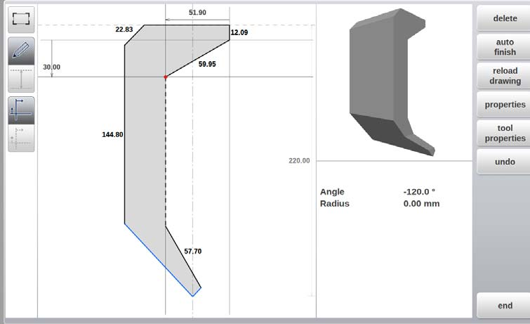
Wykrojnik do ościeżnicy
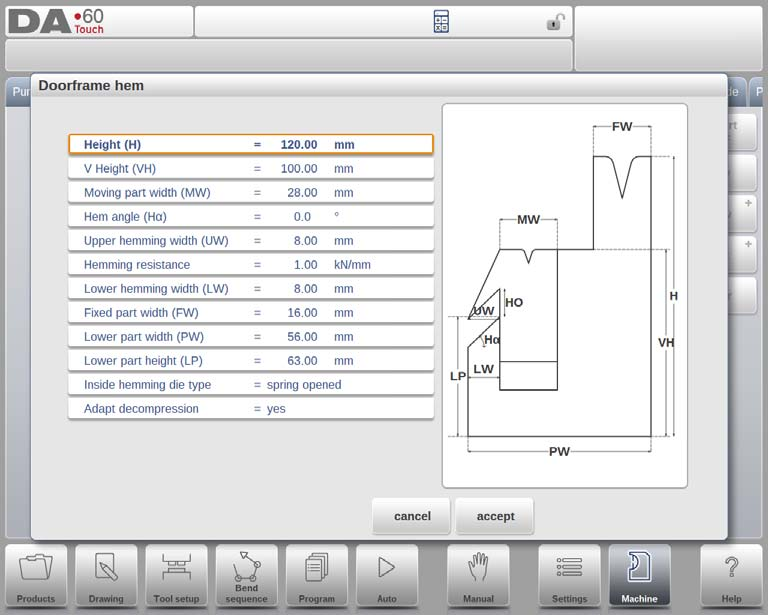
- Wysokość (H): Określa całkowitą wysokość narzędzia i jest niezbędna do obliczenia głębokości gięcia.
- Wysokość V (VH): Używane podczas operacji podwijania, określa wysokość jednostki podwijającej.
- Szerokość ruchomej części (MW): Definiuje szerokość ruchomej części lub jednostki zaginającej wykrojnika.
- Kąt rąbka (Ha): Kąt jednostki zaginającej ma kluczowe znaczenie dla precyzyjnego gięcia.
- Szerokość górnego obszycia (UW): Określa szerokość górnego segmentu używanego przy obszywaniu.
- Otwarcie dołu (HO): Wysokość matrycy w stanie otwartym, umożliwiająca umieszczenie produktu.
- Odporność na obszywanie: Maksymalna siła, jaką narzędzie wytrzymuje podczas obszywania.
- Szerokość dolnego podwinięcia (LW): Szerokość dolnego segmentu wykrojnika biorącego udział w obszyciu.
- Stała szerokość części (FW): Szerokość stałej części matrycy.
- Szerokości części górnej i dolnej: Określ wymiary tych segmentów kostki.
- Wysokość dolnej części (LP): Wysokość dolnej części kostki.
Rodzaje wykrojników do zawijania wewnętrznego
- Otwarcie wiosny:
- Wykorzystuje wewnętrzną sprężynę do początkowego ustawienia matrycy w pozycji górnej.
- Wstępne gięcie: Arkusz umieszczany jest na otwartej matrycy w celu wykonania wstępnego gięcia pod wymaganym kątem.
- Hem-Bend: polega na umieszczeniu wstępnie wygiętego produktu w otworze podwinięcia w celu ostatecznego wygięcia.
- Otwarte i zamknięte: Standardowo zablokowane do normalnego gięcia, odblokowane do podwijania.
- Normalnie zamknięte: Matryca pozostaje zamknięta podczas normalnych gięciach; należy ją aktywować w celu wykonania podwinięcia.
Adaptacja dekompresji: Określa, czy wartość otwarcia rąbka zwiększa odległość dekompresji, co jest kluczowe dla matryc otwieranych sprężynowo. Dostępne opcje to „nie”, „tak” i „wygięcie pneumatyczne”.
Właściwości otwierania V
- Promień, kąt V, otwór V: Definiuje promień krawędzi i wymiary otworu matrycy.
- Opcje dolne V:
- „Standard”: Ostry kąt.
- „Okrągły”: Dół o promieniu określonym przez „Promień wewnętrzny”.
- „Płaskie”: Płaskie dno z określoną „Szerokością dna”.
Rysowanie narzędzi i importowanie plików DXF
Po skonfigurowaniu tych parametrów można utworzyć rysunek narzędzia, wprowadzając wartości kąta i długości linii. Tryb maszynowy DELEM DA-69T obsługuje import plików DXF dla wykrojników do ościeżnic, zapewniając, że korpus wykrojnika znajduje się na warstwie 0, co umożliwia prawidłowe przetwarzanie.
Wingbend die
Kluczowe parametry:
- Odległość od punktu obrotu do góry:Niezbędne do określenia działania narzędzia na podstawie jego punktu obrotu.
- Promień skrzydeł: Istotne dla precyzyjnych obliczeń ruchu.
- Szerokość skrzydła: Ważne przy obliczeniach cofania.
Wymiary i cechy:
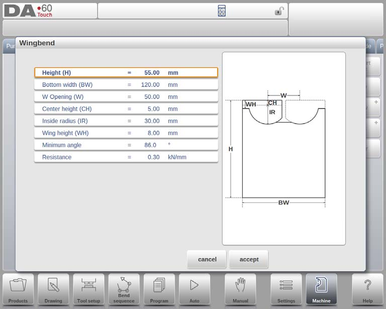
- Wysokość (H):Całkowita wysokość narzędzia, kluczowa dla obliczenia głębokości gięcia.
- Szerokość dołu (BW):Szerokość narzędzia w trybie maszyny DELEM DA-69T.
- Otwarcie W (W): Odległość między punktami obrotu.
- Wysokość środka (CH):Wysokość skrzydła nad wewnętrznym punktem obrotu.
- Promień wewnętrzny (IR):Promień skrzydła mierzony od wewnętrznego punktu obrotu.
- Wysokość skrzydła (WH):Część wysokości narzędzia obejmująca skrzydło.
- Minimalny kąt: Najmniejszy kąt możliwy do uzyskania za pomocą narzędzia.
- Opór: Maksymalna dopuszczalna siła nacisku na narzędzie.
Właściwości Wingbend
W trybie maszynowym DELEM DA-69T właściwości narzędzia wingbend są kluczowe dla personalizacji i precyzji. Właściwości te można łatwo edytować w definicji narzędzia:
- Szerokość (szer.): Dotyczy to odległości pomiędzy punktami obrotu.
- Wysokość środka (CH): Jest to wysokość skrzydła ponad wewnętrznym punktem obrotu.
- Promień wewnętrzny (IR): Promień skrzydła mierzony od jego wewnętrznego punktu obrotu.
- Przerwa (G): Odległość między skrzydłami zapewniająca prawidłowe działanie narzędzia.
- Szerokość skrzydła (WW): Definiuje szerokość górnej części skrzydła.
- Wysokość skrzydła (WH): Jest to wysokość skrzydła mieszcząca się w definicji wysokości narzędzia, istotna dla ruchu narzędzia.
- Wysokość dołu (BH): Reprezentuje wysokość środkowej części, a konkretnie głębokość otworu w kształcie litery V.
- Minimalny kąt: Najmniejszy kąt, jaki można wygiąć za pomocą tego narzędzia do wyginania skrzydeł.
Po zdefiniowaniu tych wartości można utworzyć rysunek narzędzia, korzystając z wbudowanych funkcji rysowania, obejmujących wprowadzanie kątów i długości linii. Narzędzia do rysowania dotykowego zapewniają elastyczność zbliżoną do metod rysowania produktów.
Import DXF (opcjonalnie)
W trybie maszyny DELEM DA-69T opcjonalna funkcja importu DXF umożliwia zaimportowanie kształtu matrycy do gięcia skrzydeł. Zwróć uwagę na następujące kwestie:
- Korpus kostki musi znajdować się na warstwie 0 rysunku DXF.
- Skrzydło, czyli część obrotowa, powinno znajdować się na osobnej warstwie. Nadanie tej warstwie nazwy „skrzydło” umożliwia automatyczny wybór typu narzędzia.
- Aby import przebiegł poprawnie, obydwie części w pliku DXF muszą mieć zamknięte kontury.
Korzystanie z funkcji rysowania
Podczas programowania stempli, matryc, adapterów i kształtów maszyn, sterowanie pozwala na swobodne rysowanie kształtów, co zapewnia większy realizm i precyzyjne zapobieganie kolizjom. Użytkownicy mogą najpierw naszkicować pożądany kształt, a następnie dostosować wartości segmentów lub precyzyjnie zdefiniować segmenty od samego początku.
Ważne jest, aby wiedzieć, że:
• Na koniec te kształty powinny zostać zamknięte. Funkcja automatycznego zamykania może w tym pomóc.
• Wysokość zaprogramowanego obiektu jest wykorzystywana w obliczeniach gięcia. Należy pamiętać
że jest to bardzo ważne, aby uzyskać pożądane rezultaty.
Przydatne mogą okazać się następujące informacje:
• Zarówno linii, jak i kątowi można nadać promień.

- Przyciąganie pomoże w dopasowaniu linii i kątów do otoczenia.
- Długość linii, wymiary projekcji i kąt mogą być wykorzystane do programowania. System sterowania dostosowuje wartości na podstawie ostatnich danych wejściowych, uwzględniając zmiany w wymiarach rysunku dla każdego szczegółu kształtu.

- Linie pomocnicze umożliwiają pomiar odległości między punktami i dostosowywanie punktów w razie potrzeby. Po wybraniu punktu wyświetlane są linie pomocnicze; dostosuj je, aby ustawić żądaną odległość, a punkt odpowiednio się przesunie.
- Dla Twojej wygody linie pomocnicze można wyłączyć, dzięki czemu będziesz mógł cieszyć się niezakłóconym widokiem tego, co narysowałeś.
- Jeśli sterowanie korzysta z punktów montowania w szczegółach narzędzia, punkty montowania można przełączać za pomocą rysunku. Zapobiegnie to przypadkowym, niepożądanym zmianom położenia punktu montowania lub szczegółów kształtu.
Import DXF dla narzędzi, adapterów i części maszyn
Programowanie stempli i matryc w trybie maszynowym DELEM DA-69T odbywa się za pomocą funkcji importu plików DXF, standardowego narzędzia w DA-69T. Funkcja ta umożliwia wprowadzenie niestandardowych konturów do biblioteki narzędzi maszyny, w tym stempli, matryc dolnych i adapterów.

Zacznij od otwarcia przeglądarki plików i wybrania pliku DXF zawierającego pożądany kształt. Dostosuj ustawienia konwersji, aby wybrać konkretne warstwy lub uwzględnić tylko informacje o konturach. Po wybraniu opcji „Konwertuj” zdecyduj, czy chcesz automatycznie wykryć kształt, czy określić go i przypisać identyfikator do nowego narzędzia.

Edycja narzędzi i integracja bibliotek
Po konwersji narzędzie można edytować pod kątem takich szczegółów, jak wysokość i punkty montażowe. Po zakończeniu konwersji zostanie ono dodane do biblioteki narzędzi i gotowe do użycia.
Konwersja narzędzi wielokonturowych
W przypadku narzędzi z wieloma konturami upewnij się, że warstwa głównego korpusu jest ustawiona na 0, a inne części, takie jak matryce do obszycia lub zagięcia skrzydełek, znajdują się na osobnych warstwach o odpowiednich nazwach. Aby import przebiegł pomyślnie, obie części muszą mieć zamknięte kontury w pliku DXF.
Ulepszanie działania maszyn za pomocą kątomierzy i rejestrowania zdarzeń
Kątomierz

Za pomocą tego parametru można wybrać cyfrowe urządzenie do pomiaru kąta, jeśli zainstalowano opcję Kątomierz.
Urządzenie do pomiaru kąta
Tryb maszynowy DELEM DA-69T integruje się z urządzeniami do pomiaru kąta, zapewniając precyzyjną produkcję:
- Nieużywane: Nie potrzeba żadnych urządzeń zewnętrznych.
- Mitutoyo 187-50x:Gwarantuje wiarygodne pomiary.
- Mit.187-50x U-WAVE:Pojawia się po wykryciu odbiornika bezprzewodowego.
- IBR:Obsługuje różne marki kątomierzy.
Aby uzyskać dokładność, używaj tych urządzeń w trybie produkcyjnym. Umieść kursor na polu korekcji alfa i naciśnij przycisk transmisji na urządzeniu. DELEM DA-69T wyświetli kąt. Naciśnij Enter, aby zaakceptować i obliczyć niezbędne poprawki.
Automatyczne wprowadzanie korekty α
- Wyłączony:Pokazano korektę kąta, wymagającą ręcznego wyboru i potwierdzenia.
- NA:Korekty są wprowadzane automatycznie; w trybie maszyny DELEM DA-69T nie jest wymagane wprowadzanie danych ręcznie.
Tolerancja kąta
Definiuje maksymalne odchylenie między kątami zaprogramowanymi a zmierzonymi. Znaczne różnice powodują błąd. Po włączeniu opcji „Automatyczne wprowadzanie korekcji α” automatyczne korekty zostają zatrzymane po przekroczeniu tolerancji.
Obliczanie kątów
- 180-α:Kąt jest dopełnieniem kąta iloczynowego.
- alfa:Kąt jest zgodny z kątem produktu.
Rejestrowanie zdarzeń
Jedną z kluczowych funkcji trybu maszynowego DELEM DA-69T jest możliwość rejestrowania zdarzeń w celu zarządzania produkcją. Funkcja ta umożliwia użytkownikom rejestrowanie określonych zdarzeń w sterowaniu i zapisywanie ich w plikach tekstowych do późniejszej analizy. Zrozumienie sposobu ustawiania tych parametrów ma kluczowe znaczenie dla efektywnego zarządzania i optymalizacji procesów produkcyjnych.

Rejestrowanie zdarzeń: przełączanie wł./wył.
- Nazwa pliku: Nadaj nazwę plikowi dziennika. System automatycznie doda rozszerzenie „.txt”.
- Wybór ścieżki: Wybierz miejsce przechowywania plików dziennika. Dostępne opcje to pamięć wewnętrzna, pendrive lub dysk sieciowy. Użyj funkcji „Wybierz ścieżkę”, aby określić preferowaną lokalizację.
- Maksymalny rozmiar pliku: Określ maksymalny rozmiar każdego pliku dziennika w kilobajtach. Po osiągnięciu tego limitu plik zostanie zamknięty i utworzony nowy. Zapewnia to ciągłość procesu rejestrowania bez utraty danych.
Parametry rejestrowania zdarzeń:
- Uruchomienie kontrolera: Rejestruje moment rozpoczęcia kontroli.
- Zatrzymanie kontrolera: Rejestruje moment zatrzymania sterowania.
- Zmiana skokowa: Rejestruje przejścia do następnego kroku gięcia.
- Produkt ukończony: Rejestruje ukończenie ostatniego kroku programu gięcia.
- Zmiana trybu: Rejestruje, gdy wybrany zostanie inny tryb.
- Komunikat o błędzie: Rejestruje wystąpienia komunikatów o błędach.
Struktura pliku dziennika

Każdy wiersz zdarzenia w pliku dziennika zawiera znacznik czasu i rodzaj zdarzenia. Na przykład:
- Przykład:
<log time="20100129T122021.477" event="mode" mode="1"/>
Czas jest sformatowany jako czas logowania= T, z datą przedstawioną w formacie rok-miesiąc-dzień, a godziną w formacie godziny-minuty-sekundy-milisekundy, rozdzielonymi literą „T”. Charakter zdarzenia jest identyfikowany za pomocą słów kluczowych, takich jak:
- Zmiana trybu: Atrybuty obejmują numer trybu, gdzie
1 = ręczny,2 = programowanie,3 = automatyczne,4 = krok po kroku. - Zmiana skokowa: Atrybuty mogą obejmować identyfikator produktu i numer kroku.
- Start/Stop: Atrybuty obejmują identyfikator produktu, numer kroku i stan magazynowy.
- Produkt ukończony: Atrybuty obejmują identyfikator produktu i stan magazynowy.
- Komunikat o błędzie: Atrybut jest numerem błędu.
Zagadnienia dotyczące przechowywania plików
Przy rozmiarze każdego wiersza dziennika wynoszącym około 50 bajtów, plik o rozmiarze 10 KB może rejestrować około 200 zdarzeń. Aby rejestrować dane na dużą skalę, rozważ użycie pamięci zewnętrznej, takiej jak pendrive lub lokalizacja sieciowa, obsługującej rozmiar pliku do 1 MB, co odpowiada około 20 000 zdarzeń.
Integrowanie informacji o systemie i wskazówek dotyczących konserwacji
Informacje o systemie
Aby skutecznie zaprogramować operacje wykrawania i matrycowania w trybie maszynowym DELEM DA-69T, niezbędna jest znajomość funkcji zakładki systemowej, umożliwiająca bezproblemową obsługę oprogramowania i optymalizację maszyny.

Karta trybu maszynowego DELEM DA-69T zawiera istotne szczegóły, takie jak wersje oprogramowania i identyfikatory zainstalowanych modułów, mające kluczowe znaczenie dla zadań związanych z konserwacją i serwisowaniem.
Główne funkcje i cechy
- Aplikacja: Wyświetla aktualną wersję aplikacji na maszynie DELEM DA-69T.
- Identyfikator opcji: Unikalny identyfikator opcji sterowania dla Twojej maszyny.
- Sekwencer:Pokazuje aktualną wersję sekwencera niezbędną do programowania sekwencji.
- Delem.def: Wskazuje wersję uruchomionego pliku delem.def.
- Moduły:Wyświetla listę identyfikatorów modułów i wersji pamięci flash, z przewijalnym dostępem do więcej niż czterech elementów.
Zarządzanie oprogramowaniem i systemami
- Aktualizacja oprogramowania: Zainstaluj aktualizacje przez USB, korzystając z przeglądarki katalogów w celu dokonania wyboru.
- System kopii zapasowych:Wykonuj kompletne kopie zapasowe systemu na pamięci USB, obejmujące oprogramowanie Delem, dane OEM i pliki użytkownika.
- Przywróć system:Przywróć poprzednie kopie zapasowe z możliwością wyboru przywracania komponentów.
- Oprogramowanie offline:Generuje pliki instalacyjne oprogramowania offline na nośniku USB, zapewniając kompatybilność z oprogramowaniem sterującym i optymalizując działanie.
Konserwacja
W tej sekcji opisano funkcje konserwacyjne dostępne w trybie maszyny DELEM DA-69T. Funkcje te są niezbędne do zapewnienia wydajnej pracy i długiej żywotności maszyny.

Godziny i uderzenia
- Godziny: Wyświetla całkowitą liczbę godzin pracy maszyny, co jest istotne przy planowaniu konserwacji.
- Udar mózgu:Wskazuje liczbę suwów wykonanych przez belkę prasy, zapewniając przegląd wykorzystania maszyny.
Tryb diagnostyczny
- AktywacjaTryb diagnostyczny jest niezbędny do celów serwisowych. Można go aktywować, wprowadzając specjalny kod, co wymaga kontaktu z producentem maszyny w celu uzyskania niezbędnego kodu dostępu.
- Dezaktywacja:Aby dezaktywować, wystarczy wpisać „0” w tym samym polu.
Zarządzanie ekranem
- Kalibracja ekranu dotykowego: Dostosuj ustawienia kalibracji ekranu do preferencji użytkownika, aby zapewnić optymalną interakcję.
- Ekran blokady: Skorzystaj z funkcji blokady ekranu, aby uniemożliwić wprowadzanie zmian podczas czyszczenia. Odblokowanie odbywa się poprzez naciśnięcie przycisku STOP.
Utwórz plik .dat
- Utworzenie pliku .dat w trybie diagnostycznym może pomóc w udokumentowaniu krytycznych danych produktu i sterowania. Jest on automatycznie zapisywany na podłączonym nośniku USB i może być niezbędny do wsparcia konserwacyjnego.
Wymiana modułu
Wymianę modułów osi w maszynie DELEM DA-69T można wykonać bez konieczności posiadania specjalistycznego dostępu, wykonując następujące czynności:
- Wyłącz i odłącz:Wyłącz sterowanie DA i odłącz moduł DM, który wymaga wymiany.
- Podłącz nowy moduł: Podłącz nowy moduł DM tego samego typu i włącz maszynę.
- Komunikat o błędzie:Pojawi się komunikat o błędzie wyświetlający identyfikator oryginalnego modułu.
- Dostęp do trybu maszynowego:Wejdź w tryb maszyny i przejdź do zakładki Konserwacja.
- Zainstaluj moduł: Gdy pojawi się monit, naciśnij Zainstaluj moduł.
- Potwierdzenie: Pojawi się okno z prośbą o potwierdzenie wymiany modułu. Kliknij „Tak”, aby kontynuować.
- Ponowne uruchomienie i aktualizacja:Sterowanie zostanie ponownie uruchomione w celu zainicjowania nowego modułu, a niezbędne aktualizacje oprogramowania zostaną przeprowadzone automatycznie.
Często zadawane pytania (FAQ)
Co powinienem zrobić, jeśli podczas korzystania z trybu maszynowego DELEM DA-69T pojawi się komunikat o błędzie?
Jeśli w trybie maszyny DELEM DA-69T pojawi się komunikat o błędzie, zapoznaj się z instrukcją obsługi urządzenia, aby uzyskać wskazówki dotyczące rozwiązywania problemów. Typowe problemy często można rozwiązać, sprawdzając dostępność aktualizacji oprogramowania lub upewniając się, że wszystkie połączenia i konfiguracje są poprawne.
Jaka jest najlepsza metoda programowania złożonych kształtów w trybie maszynowym DELEM DA-69T?
W przypadku złożonych kształtów należy skorzystać z graficznego interfejsu trybu maszynowego DELEM DA-69T. Rozłóż kształt na prostsze komponenty i skorzystaj z opcji programowania krok po kroku. Testowanie na prototypie z wykorzystaniem odpadów może również pomóc w dopracowaniu procesu.
Czy mogę zapisać programy niestandardowe w trybie maszynowym DELEM DA-69T do wykorzystania w przyszłości?
Tak, tryb maszyny DELEM DA-69T umożliwia zapisywanie niestandardowych programów stempli i wykrojników. Funkcja ta jest szczególnie przydatna w przypadku powtarzalnych operacji, umożliwiając szybką konfigurację i powtarzalne rezultaty.
Wniosek
Aby opanować programowanie stempli i matryc w trybie maszynowym DELEM DA-69T, kluczowe jest zrozumienie interfejsu maszyny, precyzyjna konfiguracja parametrów narzędzi i zastosowanie prawidłowej sekwencji operacji. Te kroki są kluczowe dla zapewnienia optymalnej wydajności i precyzji maszyny w projektach.
Przestrzegając tych wytycznych, możesz zwiększyć swoją produktywność i zmniejszyć liczbę błędów operacyjnych. Wdrażaj te strategie, aby w pełni wykorzystać możliwości swojej maszyny DELEM DA-69T.
Aby uzyskać dalszą pomoc lub dowiedzieć się więcej o funkcjach trybu maszynowego DELEM DA-69T, skontaktuj się z naszym zespołem. Zapoznaj się również z naszą dokumentacją, aby uzyskać więcej informacji na temat maksymalizacji potencjału Twojego sprzętu.


