


يوفر دليل تشغيل DELEM DA-66T دليلاً خطوة بخطوة لمساعدتك في تشغيل مكبس الثني CNC بسلاسة، مما يضمن تحسين الأداء والدقة في مهام الانحناء الخاصة بك.
يوفر دليل تشغيل DELEM DA-66T تعليمات مفصلة حول تهيئة واستخدام مكبس الثني CNC. اتبع هذا الدليل لإعداد سلس، وثني دقيق، وأداء مثالي للماكينة.
دعونا نغوص في ديليم DA-66T المميزات وكيفية إعدادها لتشغيل مكبس الثني بدقة وكفاءة.
نظرة عامة على التشغيل والمقدمة العامة
⒈ وحدة التحكم
يبدو التحكم على النحو التالي:
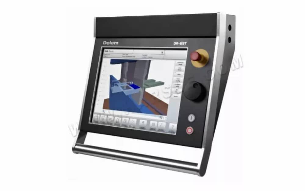
قد يختلف الزي الدقيق للتحكم الخاص بك.
يتم تشغيل وحدة التحكم بشكل رئيسي عبر شاشة اللمس. ستجد وصفًا للوظائف وأدوات التحكم باللمس المتاحة في الأقسام التالية من هذا الدليل، بالإضافة إلى وصف الوظائف المحددة.
بجانب عناصر التحكم باللمس، يتكون الجزء الأمامي من عنصر التحكم من زر التوقف في حالات الطوارئ، وعجلة اليد، وأزرار البدء والإيقاف.
مفاتيح الوظائف الخاصة، المُثبّتة في اللوحة العلوية لوحدة التحكم، لها وصف مُحدّد مُطابق لدليل المستخدم هذا، وسيتم توفيرها من قِبل الشركة المُصنّعة للجهاز. يُركّز دليل المستخدم هذا على برنامج التحكم ووظائف الجهاز ذات الصلة.
⒉عناصر التحكم الأمامية
تتكون اللوحة الأمامية، بجانب الشاشة، من عناصر التحكم التالية:

⒊ موصلات USB

⒋أوضاع التشغيل والبرمجة
تبدو الشاشة الرئيسية للتحكم DA-Touch على النحو التالي:
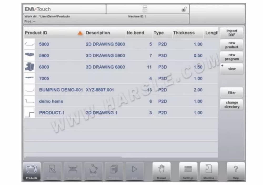
تختلف الشاشة باختلاف زر التنقل النشط. ستظهر الشاشة الرئيسية أعلاه مع تفعيل وظيفة المنتجات.
بمجرد النقر على الأوضاع المختلفة، سيتم تحديد الوضع المحدد.
هيكل الشاشة الرئيسية هو كما يلي:
لوحة العنوان
تظهر لوحة العنوان دائمًا في الأعلى. في هذه المنطقة، يمكنك العثور على معلومات الشعار، والمنتج المُحمّل، والانحناء النشط، والدليل الفرعي المُحدد، وصف الخدمة (عند تفعيله). كما يمكنك العثور على مؤشرات الجهاز هنا.

لوحة المعلومات
في لوحة المعلومات، يتم عرض جميع الوظائف والتصورات المتعلقة بالوضع المحدد ويمكن العثور عليها.

لوحة الأوامر
تعتبر لوحة الأوامر جزءًا من لوحة المعلومات وهي الموقع الذي يمكن العثور فيه على عناصر التحكم المتعلقة بلوحة المعلومات.
لوحة التنقل
لوحة التنقل هي المنطقة التي تضم جميع الأوضاع الرئيسية. هذه المنطقة مرئية دائمًا. يمكن استخدام عناصر التحكم، وهي أزرار كبيرة مزودة بأيقونات، للتبديل مباشرةً من وضع إلى آخر.
شرح الأوضاع الرئيسية / أزرار التنقل

⒌البدء
⑴ المقدمة
للحصول على برنامج ثني لمنتج، يُتيح عنصر التحكم إمكانية إنشاء رسم للمنتج وحساب تسلسل ثني صحيح له. باستخدام هذه المعلومات، يُنشأ برنامج ثني للمنتج.
يتم ذلك من خلال الخطوات التالية:
① انتقل إلى وضع المنتجات في لوحة التنقل وابدأ منتجًا جديدًا بالنقر فوق منتج جديد.
② أدخل خصائص المنتج وابدأ في رسم ملف تعريف المنتج ثنائي الأبعاد في وضع الرسم.
③ تحقق من الأدوات، وقم بتعديلها أو إنشاء إعداد جديد في وضع إعداد الأداة.
④ استخدم وضع تسلسل الانحناء لتحديد تسلسل الانحناء عن طريق حسابه أو تعديله يدويًا بناءً على فكرتك الخاصة.
⑤ عند الحاجة، قم بتعديل برنامج CNC الرقمي عبر وضع البرنامج.
⑥ اضغط على زر "تلقائي" ثم اضغط على زر "ابدأ" لإنتاج المنتج المبرمج.
⑵التحضيرات
قبل البدء في برمجة المنتج، لا بد من إجراء التحضيرات التالية.
يجب برمجة خصائص المواد الصحيحة في مكتبة المواد. يمكنك العثور على هذه المعلومات في صفحة المواد ضمن وضع الإعدادات.
يجب برمجة الأدوات الصحيحة في مكتبة الأدوات. الأدوات ضرورية لإنشاء برنامج CNC. يمكنك العثور على مكتبات أنواع الأدوات المختلفة في وضع الآلة.
⑶ إنشاء رسم
يتيح لك هذا التحكم إنشاء رسم للمنتج المطلوب. باستخدام هذا التطبيق، انقر على "رسم" في لوحة التنقل، ليتم إنشاء رسم ثنائي الأبعاد أو ثلاثي الأبعاد للمنتج. في هذه المرحلة، لا حاجة لحساب الانحناءات أو الأبعاد: يمكنك إنشاء أي رسم أو ملف تعريف.
رسم تخطيطي
يمكن رسم شكل المنتج والأداة بالنقر على الشاشة في مختلف الاتجاهات. سيتبع التطبيق النقر برسم خط بين النقاط المحددة. ستظهر النقطة الأخيرة من التصميم دائمًا بنقطة حمراء كبيرة.
عندما تظهر نقطة الرسم على الشاشة، يمكنك تثبيت إصبعك على هذا الموضع وتحريكه عبر الشاشة لتحريك الخط المتصل في الاتجاه المطلوب أو زيادة طوله. تُعرف هذه الطريقة باسم "السحب". ستظهر قيمة الطول والزاوية على الشاشة، ويمكن تعديلها لتكون دقيقة أو قريبة من القيمة المطلوبة.
تحديد القيمة
بعد رسم المنتج أو الأداة بطريقة الرسم التخطيطي، يُمكن تحسين القيم الدقيقة لأطوال الخطوط وزواياها باستخدام طريقة ضبط القيمة. ما عليك سوى النقر مرتين على قيمة طول الخط أو الزاوية لتغييرها، وستظهر لوحة المفاتيح.
وظيفة التكبير
بالضغط على الشاشة بإصبعين في آنٍ واحد، يُمكن تكبير وتصغير الرسم أو الأداة أو عرض الآلة. بفرد الأصابع، يُكبّر النظام الصورة، وبتقريب الأصابع، يُصغّرها.
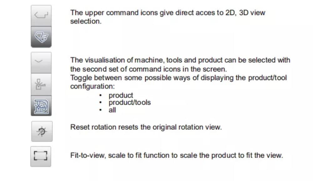
ملائمة للشاشة
ستجد في أيقونات الأوامر على جانب الشاشة وظيفة "ملاءمة الشاشة". يمكنك استخدامها عندما لا يكون حجم الرسم واضحًا في الصورة. ما عليك سوى النقر مرة واحدة، وسيُصبح حجم الرسم كاملًا ليناسب شاشة الرسم.
التنقيب
بلمس إصبعين متزامنين وسحبهما على الشاشة (مع تحريكهما في نفس الاتجاه)، يُمكن تحريك الكائن في عرض ثلاثي الأبعاد. في العرض ثنائي الأبعاد، يُتيح إصبع واحد التحريك أيضًا.
الدوران
في تقنية ثلاثية الأبعاد، يمكن تدوير المنتج أو الأداة أو التصور الميكانيكي من خلال تحريك إصبع واحد على الشاشة.
يمكن العثور على مزيد من المعلومات حول هذا الموضوع في الفصل الثالث.
⑷ تحديد تسلسل الانحناء
عند اكتمال رسم المنتج، يُتيح لك نظام التحكم وضع إعداد الأداة لبرمجة إعداد الأداة بدقة وفقًا لترتيبها على الآلة. بعد ذلك، يمكنك اختيار وضع تسلسل الانحناء لتحديد ومحاكاة تسلسل الانحناء المطلوب.
في وضع تسلسل الانحناء، يعرض عنصر التحكم المنتج والآلة والأدوات. في هذه القائمة، يمكن برمجة تسلسل الانحناء وفحصه بصريًا. عند تحديد تسلسل انحناء، يمكن إنشاء برنامج CNC. للمزيد من المعلومات حول هذا الموضوع، يُرجى الاطلاع على الفصلين الرابع والخامس.
⑸البرنامج العددي
تتيح لك قائمة البرنامج الوصول إلى البرنامج الرقمي وقيم المنتج النشط.
هناك طريقتان لإنشاء برنامج CNC:
• أدخل برنامجًا رقميًا، يتم البدء به عبر وضع المنتجات، ثم انقر فوق برنامج جديد، خطوة بخطوة؛
• قم بإنشاء البرنامج من محاكاة الانحناء الرسومية التي بدأت عبر وضع المنتجات، ثم انقر فوق منتج جديد، عبر وضع الرسم. (انظر: وضع الرسم؛ رسم المنتج).
إذا تم إدخال البرنامج يدويًا، فلن يكون هناك فحص تصادم. يجب إدخال جميع قيم البرنامج يدويًا. يعتمد البرنامج على خبرة المُشغّل. إذا تم توليد البرنامج من تسلسل انحناءات رسومي، فيمكن عرضه أثناء الإنتاج. ويمكن تعديل البرنامج المُولّد وفقًا لاحتياجات التشغيل.
يمكنك العثور على مزيد من المعلومات حول هذا الموضوع في الفصل السادس.
⑹القائمة التلقائية والقائمة اليدوية وأوضاع الإنتاج
يمكن تنفيذ برنامج المنتج عبر الوضع التلقائي. في الوضع التلقائي، يمكن تنفيذ البرنامج بالكامل ثنيةً تلو الأخرى. في الوضع التلقائي، يمكن اختيار وضع الخطوة لبدء كل ثنية على حدة.
الوضع اليدوي للتحكم هو وضع إنتاج مستقل. في هذا الوضع، يمكن برمجة انحناءة واحدة وتنفيذها. ويُستخدم عادةً لاختبار أداء نظام الانحناء.
يمكن العثور على مزيد من المعلومات حول هذا الموضوع في الفصلين 7 و 8.
⑺نسخ البيانات احتياطيًا، التخزين الخارجي
يمكن تخزين ملفات المنتجات والأدوات خارجيًا. وحسب الإعدادات، يمكن تخزين هذه الملفات على شبكة أو على وحدة تخزين USB. يُسهّل هذا النسخ الاحتياطي للبيانات المهمة وتبادل الملفات بين وحدات تحكم Delem.
يمكنك العثور على مزيد من المعلومات حول هذا الموضوع في الفصل التاسع.
⒍مساعدات البرمجة
⑴ نص المساعدة
هذا العنصر مُجهّز بوظيفة مساعدة فورية. عند الضغط على زر المساعدة في لوحة التنقل، ستظهر مساعدة مُراعية للسياق.
لتنشيط نافذة المساعدة لمعلمة ما، انقر فوق زر المساعدة في لوحة التنقل.
تظهر نافذة منبثقة تحتوي على معلومات حول المعلمة النشطة.
تحتوي نافذة "المساعدة" هذه على نفس المعلومات الموجودة في دليل التشغيل.
يمكن استخدام نافذة المساعدة على النحو التالي:
يمكنك تصفح النص بتحريك إصبع واحد في الاتجاه المطلوب. بالنقر على الجزء السفلي أو العلوي من الشاشة، يمكنك استخدام "الصفحة السابقة" أو "الصفحة التالية" لتصفح نص المساعدة.
تساعد وظيفة الفهرس على الانتقال مباشرةً إلى جدول المحتويات. تساعد الروابط التشعبية في الجدول على الوصول مباشرةً إلى الموضوع المطلوب.
اضغط على "إنهاء" لإغلاق نافذة "المساعدة".
⑵وظيفة Listbox
تحتوي العديد من معلمات وحدة التحكم على عدد محدود من القيم الممكنة. عند تحديد هذه المعلمة، بالنقر على خط المعلمة على الشاشة، ستظهر قائمة الخيارات بالقرب من موضع النقر، ويمكنك اختيار القيمة المطلوبة.
⑶التصفية، البحث المباشر
في بعض الأوضاع، تُعرض قائمة بالكيانات (المنتجات، الأدوات، المواد، إلخ). ومن أمثلة هذه القوائم وضع "المنتجات" (اختيار المنتج). للبحث عن منتج أو أداة معينة، يمكن استخدام خاصية التصفية. اضغط على زر الأمر "تصفية"، واكتب جزءًا من المعرف في حقل الإدخال. تلقائيًا، تقتصر القائمة على العناصر التي تحتوي على الجزء المكتوب.
⑷ الملاحة
في بعض الأوضاع، يتم تقسيم شاشات البرنامج إلى علامات تبويب.

⑸إدخال النص وتحريره
يمكن استخدام المؤشر لإدخال قيمة أو نص محدد ضمن مُدخل موجود. ما عليك سوى النقر على الموضع المطلوب. سيظهر المؤشر وستتم إضافة المُدخلات إليه. على سبيل المثال، في "تحرير الملاحظات"، حيث يُمكن إدخال أسطر متعددة. يُستخدم زر الإدخال لتغذية الأسطر. تتوفر وظائف القص والنسخ واللصق على لوحة المفاتيح لتسهيل التحرير. كما يُمكن استخدام التراجع والإعادة داخل هذا المُحرر.
⑹كتابة الأحرف الأبجدية الرقمية مقابل الأحرف الخاصة
يمكن استخدام كلٍّ من الأحرف الأبجدية الرقمية والأحرف الخاصة في جميع أنحاء عنصر التحكم. ستظهر لوحة مفاتيح أبجدية رقمية كاملة على الشاشة عند الحاجة. عند تحرير حقل رقمي بحت، ستظهر الأحرف الأبجدية الرقمية "رمادية اللون" ولا يمكن استخدام سوى لوحة المفاتيح الرقمية. بالنسبة للحقول التي تسمح باستخدام الأحرف الأبجدية الرقمية،
السلاسل، لوحة المفاتيح متاحة بالكامل. الأحرف الخاصة مثل ? % - يمكن العثور عليها باستخدام زر الأحرف الخاصة في الجانب الأيسر السفلي من لوحة المفاتيح.
⑺آلة حاسبة
يوفر نظام التحكم الرقمي بالكمبيوتر (CNC) "آلة حاسبة مكتبية" متاحة للمشغل. يمكن استخدام رمز الآلة الحاسبة في أعلى الشاشة للانتقال إلى وظيفة الآلة الحاسبة. توفر منطقة لوحة المفاتيح وظائف الآلة الحاسبة التي يمكن استخدامها بشكل مستقل. قياسي
تتوفر وظائف (الجمع والطرح والضرب والقسمة) بما في ذلك النسبة المئوية والجذر التربيعي والمربع ووظائف الذاكرة.
⑻الشبكة
وحدة التحكم الرقمية (CNC) مُجهزة بواجهة شبكة. تتيح وظيفة الشبكة للمشغلين إمكانية استيراد ملفات المنتج مباشرةً من مجلدات الشبكة أو تصدير ملفات المنتج النهائي إلى مجلد الشبكة المطلوب.
⑼ وظيفة قفل المفتاح
لمنع حدوث تغييرات في المنتجات أو البرامج، توفر وظيفة قفل المفاتيح إمكانية قفل عنصر التحكم.
⑽لوحة وظيفة OEM
اعتمادًا على تنفيذ الشركة المصنعة للآلة، يمكن استخدام الزاوية اليمنى العليا من الشاشة للمؤشرات الخاصة.
للوصول إلى الوظائف المتعلقة بتلك المؤشرات، يمكن فتح لوحة وظائف OEM من خلال النقر على هذه الزاوية من الشاشة.
⑾إصدارات البرامج
يتم عرض إصدار البرنامج الموجود تحت سيطرتك في علامة التبويب "معلومات النظام" في قائمة "الجهاز".
المنتجات، مكتبة المنتجات
⒈ المقدمة

⑴ المنظر الرئيسي

في وضع المنتجات، تُعرض نظرة عامة على مكتبة البرامج في وحدة التحكم. في هذا الوضع، يمكن اختيار (تحميل) برنامج المنتج. بعد ذلك، يمكن تعديل البرنامج أو تنفيذه. يتكون كل عنصر في القائمة من صورة مصغّرة للمنتج الرسومي (يظهر رمز للبرامج الرقمية)، ومعرف المنتج، ووصف المنتج، وعدد الانحناءات في المنتج، ونوع المنتج (النوع)، وتاريخ آخر استخدام أو تعديل له. مؤشر النوع
يظهر المنتج الأنواع التالية من المنتجات:
ص– المنتج لديه برنامج CNC، لا يوجد رسم
-2D المنتج يتكون من رسم ثنائي الأبعاد، ولا يوجد برنامج CNC
من 2 إلى 1 المنتج يحتوي على رسم ثنائي الأبعاد وبرنامج CNC
-ثلاثي الأبعاد المنتج عبارة عن رسم ثلاثي الأبعاد، ولا يوجد برنامج CNC
بي 3 دي المنتج يحتوي على رسم ثلاثي الأبعاد وبرنامج CNC
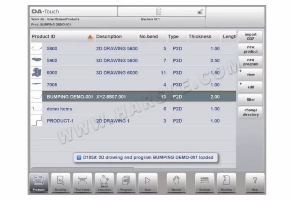
⑵ اختيار المنتج
لاختيار منتج، يكفي نقرة واحدة. سيتم اختيار المنتج وتحميله إلى الذاكرة. من هنا، يمكن بدء الإنتاج بالضغط على "تلقائي". كما يمكن بدء التنقل عبر رسم المنتج (إن وجد)، وإعدادات الأدوات، وتسلسل الانحناء، والبرنامج الرقمي للمنتج.
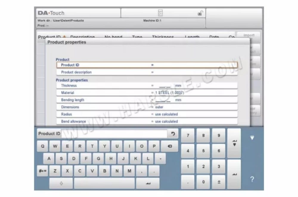
⑶منتج جديد، بدء منتج رسومي جديد
لبدء منتج رسومي جديد، انقر فوق منتج جديد.
بعد اختيار منتج جديد، تبدأ برمجة المنتج الجديد بتفاصيله العامة مثل معرف المنتج والسمك والمادة.
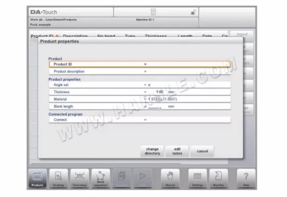
⑷برنامج جديد، بدء برنامج عددي
لبدء برنامج رقمي جديد، انقر فوق برنامج جديد.
بعد اختيار برنامج جديد، تبدأ البرمجة بتفاصيله العامة، مثل معرف المنتج، والسُمك، والمادة. تظهر علامة التبويب العامة بجوار علامات التبويب التالية الجاهزة لبرمجة الانحناءة الأولى.
⑸ المشاهدات
لعرض المنتجات كقائمة بسيطة أو بشكل رسومي بالكامل، يمكنك استخدام وظيفة "العرض". بالنقر على "عرض"، يمكنك اختيار أحد أوضاع العرض الثلاثة.

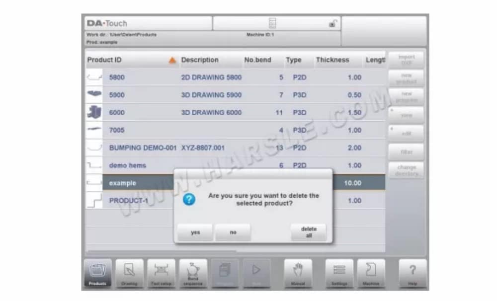
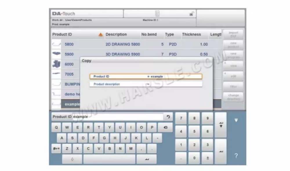
⑹تحرير ونسخ وحذف منتج أو برنامج
لحذف منتج في وضع المنتجات، حدده بالنقر عليه. سيتم تحديده. بعد ذلك، انقر على "تحرير" ثم استخدم "حذف". لحذفه نهائيًا، أكّد السؤال. لحذف جميع المنتجات والبرامج دفعةً واحدة، انقر على "حذف الكل".
لنسخ منتج، حدد المنتج أو البرنامج، ثم انقر على "تحرير" ثم "نسخ". بعد ذلك، يُمكن برمجة اسم المنتج، وسيتم النسخ. سيظهر المنتج في نفس المجلد. ستكون النسخة المنسوخة مطابقة تمامًا، بما في ذلك إعدادات الأداة وخصائصها.
التسلسل إذا كان متاحًا.
⑺ قفل المنتج/فتحه
توفر وظيفة قفل/فتح المنتج طريقة بسيطة لمنع التغييرات غير المقصودة في البرامج أو المنتجات النهائية. بهذه الطريقة، لا يمكن تغيير المنتجات التي تم ضبطها وثبتت جودتها إلا بعد فتح قفل المنتج.
عند النقر على تحرير، يمكن التبديل بين ميزة قفل المنتج / إلغاء قفل المنتج لكل منتج أو برنامج.

⑻ وظيفة التصفية
لتسهيل العثور على المنتجات، تعمل وظيفة التصفية على تمكين عمليات البحث المباشرة من خلال وضع المنتجات.
عند النقر على "تصفية"، ستظهر شاشة التصفية. بكتابة سلسلة التصفية المطلوبة، مع فصلها بمسافات اختيارية، سيبدأ البحث المباشر.
اختياريًا، يمكنك اختيار عرض مختلف. كما يمكنك تغيير الخاصية التي يُطبّق عليها الفلتر باستخدام "التحديد".
يمكن تحديد مُعرّف المنتج، أو وصفه، أو نوعه، أو تاريخه. يمكنك إدخال اسم كامل أو رقم، أو جزء منه فقط. إذا أدخلت جزءًا من اسم، وكان هذا الجزء موجودًا في عدة أسماء منتجات، فسيعرض عنصر التحكم جميع أسماء المنتجات التي تحتوي على هذا الجزء. كما يمكنك إدخال مزيج من الاسم والرقم.
انظر أيضًا القسم 1.6.2 حول التصفية و"البحث المباشر".

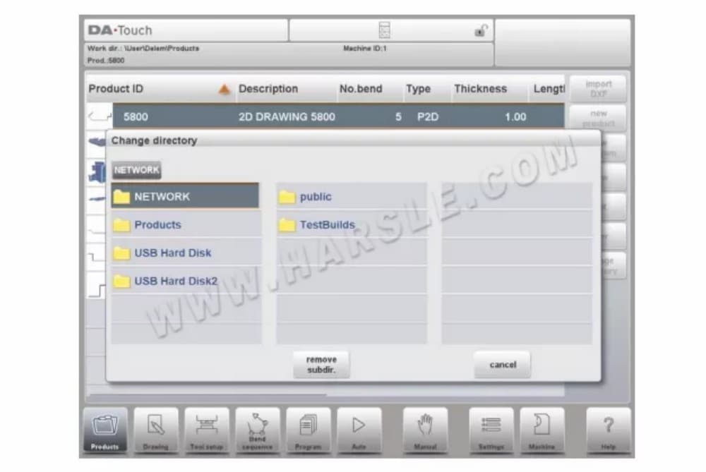
⑼ تغيير الدليل
للانتقال إلى دليل منتجات مختلف، أو لإضافة دليل منتجات جديد، انقر على "تغيير الدليل". عند الحاجة إلى إزالة دليل قديم، حدد الدليل وانقر على "إزالة الدليل". عند الوصول إلى الدليل المطلوب، انقر على "تحديد" للعودة إلى شاشة المنتجات التي تعرض جميع المنتجات في الدليل. يظهر اسم الدليل المحلي النشط في رأس الصفحة.

⑽اختيار منتج الشبكة
عند تثبيت دليل شبكة في وحدة التحكم، يُمكن العثور على هذا الدليل المُثبّت ضمن "الشبكة". يتوفر "الشبكة" بجوار دليل المنتج عند استخدام دليل التغيير. يشير اسم محرك الأقراص المُثبّت إلى إمكانية اختيار المنتج.
تخزين.
يمكن تصفح أدلة الشبكة باستخدام متصفح الأدلة. يمكن تحديد الأدلة وإضافتها وإزالتها، بالإضافة إلى اختيار المنتجات. عند الوصول إلى الدليل المطلوب، انقر على "تحديد" للعودة إلى شاشة "المنتجات" التي تعرض جميع المنتجات في
الدليل. أصبح دليل الشبكة الآن الدليل المحلي النشط. يظهر اسمه في أعلى الشاشة.
⒉خيار استيراد DXF
كبديل لرسم المنتج المطلوب في وحدة التحكم، يُمكنها أيضًا استيراد ملف إخراج خارجي لنظام CAD. سيشرح هذا الفصل استخدام محول DXF لاستيراد ملفات DXF ووظائفه. (هذه الوظيفة متوفرة اختياريًا في DA-66T للمنتجات ثنائية الأبعاد فقط).
يتم بدء خيار استيراد DXF باستخدام زر الأمر الموجود أعلى "منتج جديد". استيراد DXF
يفتح متصفح اختيار الملفات لتحديد ملف DXF.
⑴أبعاد رسم المنتج
أبعاد الإسقاط
في هذه الحالة، تكون جميع جوانب المنتج وخطوط الانحناء مساويةً لطول المنتج الناتج. لا يُمثل الرسم الحجم الحقيقي للورقة المراد ثنيها، بل هو مجرد تمثيل لكيفية تنظيم الورقة في انحناءات وأسطح. عند تحميل هذا الرسم وتحويله، يُنشئ المُحوِّل رسمًا للمنتج بنفس الأحجام الموجودة في الرسم الأصلي تمامًا. لاحقًا، تُضاف معلومات إضافية حول المادة وسمك الورقة وأبعاد المنتج. يُترك لوحدة التحكم إنشاء برنامج CNC بمواضع المحاور المناسبة، مما يُنتج المنتج بالشكل المطلوب.
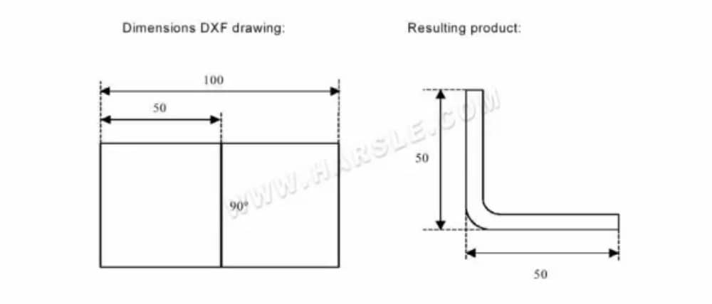
في هذا المثال، قد يكون الطول في رسم DXF الأصلي 100 ببساطة، مفصولًا بخط انحناء. سيتكون المنتج الناتج من ضلعين، طول كل منهما 50. تُعرّف الأبعاد بأنها أبعاد خارجية.
أبعاد القطع
في هذه الحالة، يُمثل رسم DXF الورقة بدقة كما هي مقطوعة وستُستخدم لثني منتج. عند ضبط مُحوّل DXF لتحويل أبعاد القطع، بناءً على مادة الورقة وسمكها، يلزم توفير معلومات بدل الانحناء أثناء عملية التحويل. في حال عدم توفر هذه المعلومات، سيطلبها المُحوّل.
سيستخدم المُحوِّل هذه الأبعاد وجدول بدل الانحناء لإنشاء رسم ثلاثي الأبعاد للمنتج بأبعاد إسقاطية. عند استخدام المنتج في وحدة التحكم، يجب استخدام جدول بدل الانحناء نفسه لإنشاء برنامج CNC قادر على معالجة ورقة كما هو موضح في رسم DXF الأصلي.
⑵ تحديد خطوط الانحناء والطبقة مع تعيين الخط
للحصول على تحويل صحيح، يعد تعيين خصائص المنتج المحددة للخطوط في DXF أمرًا مهمًا.
بناءً على محتوى ملف DXF، يُمكن تخصيص خطوط الانحناء والمحيط ومعلومات النص الإضافية طبقةً تلو الأخرى. في حال تفعيل تحديد الطبقة، يتم البحث عن خطوط الانحناء تلقائيًا.
معلومات المنتج
بجانب الرسم الفعلي للمنتج، يمكن أن يحتوي رسم DXF على معلومات أخرى، مثل اسم الشركة المصنعة وخطوط الأبعاد ووصف المنتج وما إلى ذلك. إذا تم تنظيم هذه المعلومات في طبقات أخرى غير رسم المنتج، فيمكن تصفية هذه المعلومات عن طريق التحديد
طبقات محددة فقط للتحويل. وإلا، يُمكن حذف المعلومات غير الضرورية في برنامج التحويل قبل بدء تحويل الرسم.
اختيار الطبقة
بناءً على إعدادات استيراد DXF، والتي يمكن إدخالها من الشاشة الرئيسية، يمكن تفعيل أو تعطيل تحديد الطبقات. في حالة تفعيل تحديد الطبقات، يمكن تبديل عرض قائمة خصائص الطبقات. تُمكّن الأزرار في الزاوية العلوية اليسرى هذا الخيار. توضح الفقرات التالية الفرق بين تفعيل تحديد الطبقات وتعطيله.
⑶التحويل
عندما يتم تعيين المهام بشكل صحيح، يمكن تنفيذ التحويل عن طريق النقر على
زر التحويل.
ستظهر معاينة التحويل عند وجود تحذيرات أو أخطاء. أثناء التحويل، يُمثَّل رسم DXF بخطوط مثل خط الكنتور، وخط الانحناء، وخطوط الكنتور الداخلية. تشير الألوان إلى خصائص تحويل الخطوط. ستختلف ألوان خطوط رسم المنتج بعد التحويل. لكل لون خاص به.
معنى:
• الأزرق: خط الكنتور، هذا الخط هو جزء من المحيط الخارجي للمنتج.
• الأحمر: خط الانحناء، هذا الخط هو خط الانحناء.
• الأخضر: الخط الداخلي، هذا الخط هو جزء من الخط الداخلي للمنتج.
• أسود: سيتم عرض النصوص المخصصة باللون الأسود.
⑷تحويل أبعاد القطع، مع معلومات بدل الانحناء
في المرحلة الأخيرة من تحويل ملف DXF بأبعاد القطع، يجب إعادة استخدام بدل الانحناء الذي تم استخدامه أثناء النشر في التحويل.
لذلك، سيستخدم تحويل أبعاد القطع دائمًا جدول بدل الانحناء في وحدة التحكم، وسيتحقق من توفر معلومات بدل الانحناء لجميع الانحناءات. في حال توفر مجموعة واحدة فقط من معلمات بدل الانحناء لكل انحناء، فسيتم ذلك.
مُستخدَم. ستعرض نافذة "بدل الانحناء" زوايا المنتج مع بدل الانحناء المُحدَّد. إذا كانت هناك إدخالات أخرى في الجدول صحيحة، فيجب اختيار خط بدل الانحناء المناسب. يُمكن أن يكون نصف القطر المُفضَّل والمحسوب مُفيدًا في هذا الاختيار.

⑸إعدادات DXF
في إعدادات محول DXF، يُمكنك ضبط معلمات التحويل. كما يُمكنك تخزين ملفات إعدادات متعددة لأنواع رسومات مُحددة. تتوفر وظيفتا الحفظ باسم والتحميل.
رسم المنتج
⒈الخصائص العامة للمنتج

لبدء رسم منتج جديد، اختر منتج جديد في مكتبة المنتج

⑴إضافة ملاحظات
عند الضغط على زر "تحرير الملاحظات"، تظهر نافذة جديدة يمكنك من خلالها تحرير النص المتعلق بالمنتج الحالي. تُعرض الأحرف الممكنة على لوحة المفاتيح.
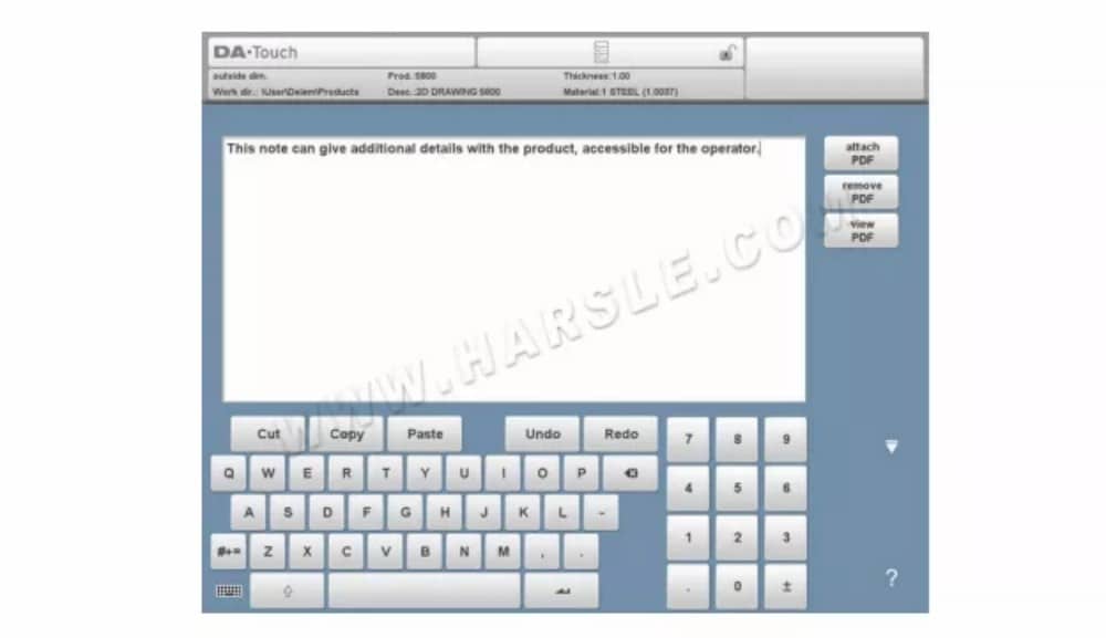
لإرفاق ملف PDF بالملاحظة، انقر على "إرفاق PDF". من خلال متصفح المجلدات، يمكنك تحديد ملف PDF وإضافته إلى ملف المنتج.
عند إرفاق ملف PDF فقط بدون ملاحظة نصية، سيتم عرض ملف PDF بشكل فوري عندما يضغط المستخدم على مؤشر الملاحظات في الوضع التلقائي.

⒉ رسم المنتج ثنائي الأبعاد
⑴ المقدمة
بعد إدخال بيانات المنتج العامة تظهر شاشة الرسم.

في صف المعلومات العلوي ستجد معلومات حول معرف المنتج ووصف المنتج واختيار الأبعاد الداخلية/الخارجية ودليل المنتج الفعلي.
يمكنك الآن إنشاء ملف تعريف المنتج. يمكنك ذلك بالنقر بأصابعك وإنشاء المنتج بسرعة في وضع "الرسم التخطيطي". بعد ذلك، يمكنك إدخال أبعاد المنتج الفعلية والقيم المقابلة باستخدام لوحة المفاتيح. كما يمكنك إدخال زاوية الانحناء وطول الضلع مباشرةً باستخدام لوحة المفاتيح وزر الإدخال. ستظهر الخصائص في شريط الإدخال على شاشة لوحة المفاتيح. يستمر هذا الإجراء حتى يصبح المنتج بالملف التعريفي المطلوب.
يمكن تغيير بيانات المنتج باختيار "خصائص المنتج". كما يمكن تغيير خصائص زوايا المنتج وخطوطه باختيار "خصائص".
⒊ خصائص الخط
⑴ المقدمة
عندما يكون المؤشر على أحد خطوط المنتجات، من الممكن تغيير خصائص هذا الخط عن طريق تحديد "خصائص".

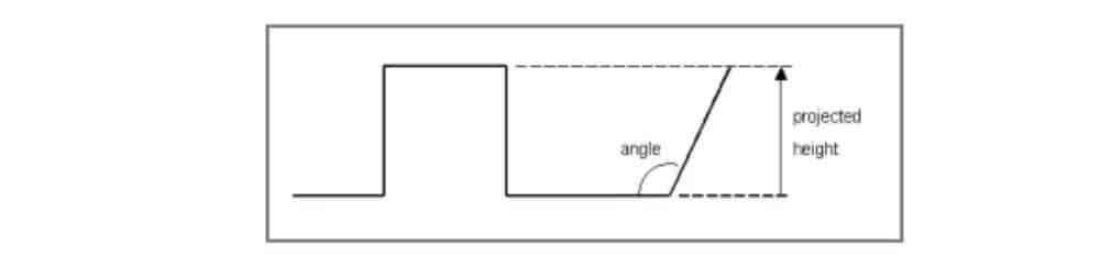
⑵ الإسقاط
داخل النافذة ذات خصائص الخط، يمكن برمجة خصائص الإسقاط التالية:
الإسقاط الأفقي
المسافة الأفقية التي يجب أن يقيسها الخط، بغض النظر عن قيمة زاويته.
الإسقاط الرأسي
المسافة الرأسية التي يجب أن يقيسها الخط، بغض النظر عن قيمة زاويته.
⑶الاختيار الدقيق
عند وضع مؤشر الرسم على قطعة خط مستقيم، يمكنك تحديد مستوى دقة هذا الخط. أدخل الخصائص ثم انتقل إلى معلمة الدقة.
دقة
حدد مستوى الدقة للخط.
عادي: تحقيق الدقة العادية لهذا الجزء.
مرتفع: في حساب تسلسل الانحناء، سيتم اختيار موضع توقف المقياس الخلفي للحصول على أعلى دقة ممكنة لفاصل الخط هذا.
البعد الختامي: عند حساب تسلسل الانحناء، سيتم اختيار موضع توقف المقياس الخلفي للحصول على التفاوتات الناتجة في فترة الخط هذه.
⒋ خصائص الانحناء
⑴ انحناء الهواء
رسم منتج بيانيًا هو ببساطة برمجة طول الخط، وقيمة الزاوية، وطول الخط التالي، إلخ، حتى يصل المنتج إلى الشكل المطلوب. للانحناءات في المنتج خصائصها القياسية أو المحددة. يمكن ضبط خصائص الانحناء باختيار الانحناء ثم اختيار "الخصائص".

⑵نصف قطر كبير: الاصطدام
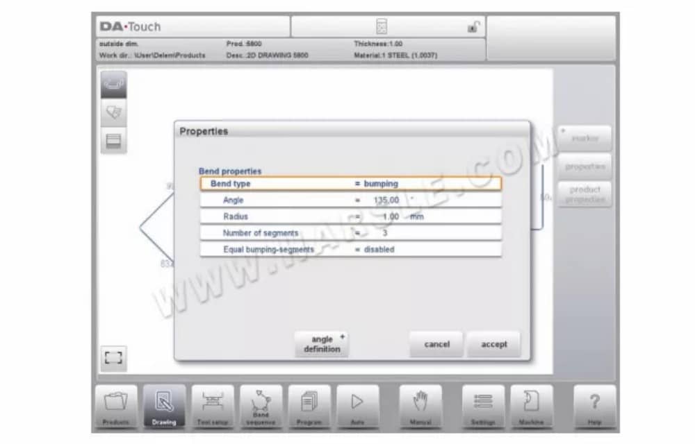
في حال عدم توفر أداة ذات نصف قطر كبير، يُمكن اختيار طريقة الارتطام. باستخدام هذه الطريقة، يتم الحصول على نصف قطر كبير للمنتج من خلال سلسلة من الانحناءات الطفيفة المتتالية.
⑶ ثنيات الحاشية
عند إنشاء الشكل المطلوب للمنتج مع ثنية الحاشية، يُمكنك أولاً تحضير شفة بزاوية ثني مسبقة، ثم وضع المؤشر على الثنية واختيار "خصائص". يُمكن برمجة خصائص الثني من النافذة المنبثقة.

من الممكن أيضًا إنشاء انحناء للحاشية بوضع المؤشر على طرف الحافة حيث يلزم انحناء الحاشية، ثم اختيار الخصائص. ستظهر نافذة منبثقة مع معلمة إضافية لملئها.
⒌علامة خط السطح أو الانحناء
باستخدام وظيفة العلامة، من الممكن وضع علامة على سطح معين أو خط انحناء، مما يحسن التعرف على الجوانب وخطوط الانحناء.
تكوين الأداة
⒈مقدمة
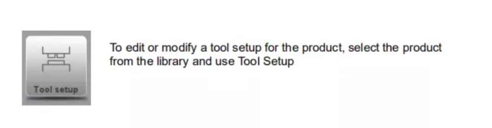
⒉ الإجراء القياسي
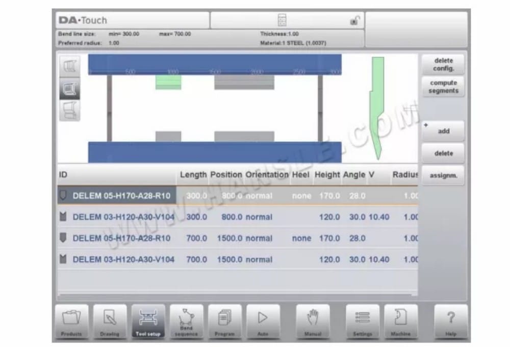
عند تفعيل وظيفة "إعداد الأدوات"، تُظهر الشاشة في النصف العلوي منها منظرًا أماميًا لإعدادات الماكينة. أما في النصف السفلي، فتُعرض بيانات الأدوات. في هذه الشاشة، يُمكن برمجة أماكن الأدوات في الماكينة.
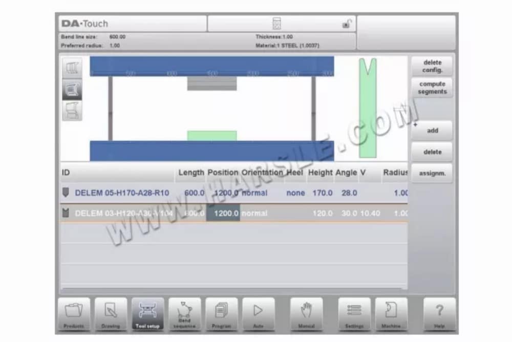
في المنظر الأمامي، يتم عرض عناصر الماكينة التالية، من الأعلى إلى الأسفل:
• الجانب العلوي للماكينة (شعاع الضغط)
• محول للثقب (إذا تم برمجة محول)
• لكمة
• يموت
• الجانب السفلي للماكينة (الطاولة).
تم تحديد أجزاء الآلة مسبقًا في وضع الآلة. عادةً، لا تتغير هذه الأجزاء. تعتمد إمكانية برمجة المحول على خيار "تمكين المحولات" في وضع الآلة نفسه.
⒊اختيار الأداة
عند بدء تكوين أداة جديدة، يكون فتح الماكينة فارغًا.

حدد إضافة لإضافة أداة إلى التكوين؛ المثقبة أو القالب أو المحول (إذا تم تمكينه).
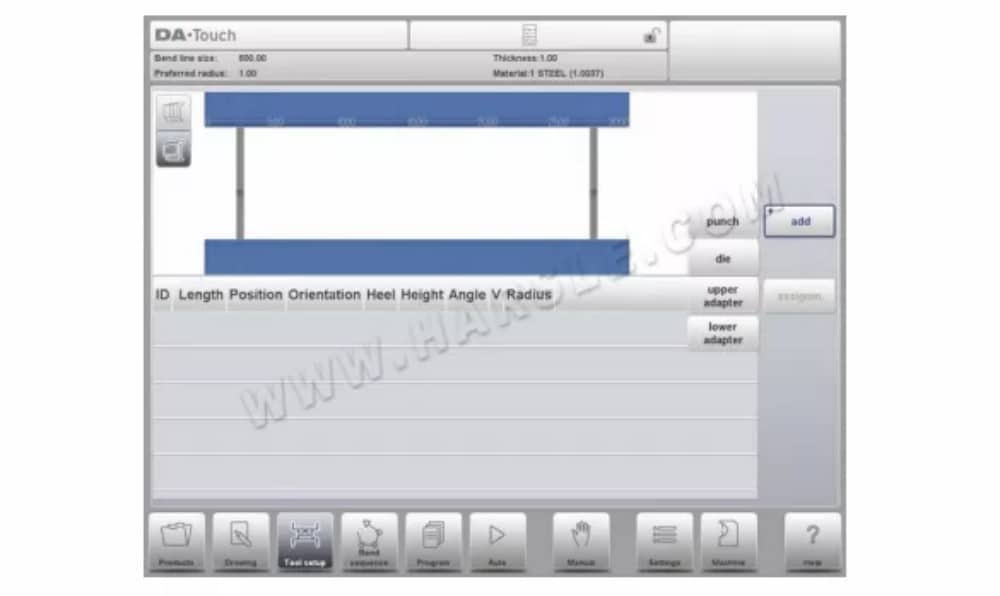
عندما يتم اختيار أداة (على سبيل المثال، لكمة)، يتم وضعها في الجهاز بأقصى طول متاح.
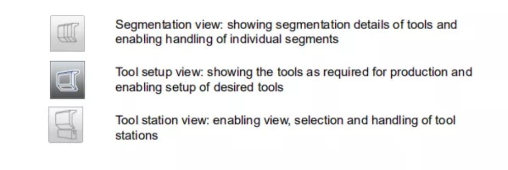
⒋تجزئة الأدوات
عند استخدام أدوات مجزأة، والتي يمكن من خلالها تكوين أدوات بالحجم المطلوب، يمكن للتحكم أن يدعم هذا ويمكن أن يساعد في إنشاء التجزئة المناسبة.
في الفقرة التالية، يتم شرح وظيفة التجزئة، بما في ذلك استخدام ثلاثة خيارات لإعداد الأداة. بجوار شاشة إعداد الأداة، تعتمد إمكانية توفر ميزات التجزئة على القطاعات المبرمجة لكل أداة. يمكن إجراء هذه البرمجة في وضع الآلة ضمن مكتبتي "الثقوب" و"القوالب السفلية". للمزيد من المعلومات حول برمجة القطاعات في مكتبة الأدوات، يُرجى الاطلاع على نهاية هذه الفقرة.
من شاشة إعداد الأداة، تتوفر ثلاثة أوضاع عرض. باستخدام أزرار الاختيار على يسار واجهة الجهاز، يمكنك اختيار الأوضاع التالية:
⒌ تقسيم الأدوات الفردية
بعد تجهيز الأدوات المطلوبة للمنتجات المراد تصنيعها، يُمكّن وضع تسلسل الانحناء من حساب تسلسل الانحناء الأكثر كفاءة. ويمكن تقسيم الأدوات حسب الرغبة، مما يُساعد في اختيار القطع اللازمة للحصول على الطول المناسب للأداة.
تحسب وظيفة تقسيم الأداة تلقائيًا التقسيم المطلوب وتستخدم التعيينات "أقصى مسافة بين الأدوات" وعند الاختيار "تسامح طول الأداة" للعثور على أفضل حل.

⑴ عرض الأداة
لتجزئة الأدوات، يمكنك الضغط على وظيفة تجزئة الأدوات في عرض الأدوات. سيقوم النظام، بناءً على أطوال القطع المبرمجة وعدد القطع المتاحة، بحساب تجزئة تلك الأداة المحددة. هذا يعني أن جميع المحطات التي تستخدم
نفس الأداة في الاعتبار (يجب برمجة أجزاء الأداة في الأدوات المحددة). بعد بدء الوظيفة، يتم عرض النتائج التي تم العثور عليها ويمكن متابعة نتائج عملية التحسين. عند العثور على تطابق دقيق، سيتحول المؤشر إلى اللون الأخضر (لاحقًا يتم تلوين لون رمز الأداة بشكل مشابه). عند العثور على طول غير دقيق ولكنه صالح، مع مراعاة التعيينات، سيتحول المؤشر إلى اللون الأصفر. يمكن أن يعني هذا أنه تم استخدام المسافة بين الأدوات أو تسامح طول الأداة. كما يمكن أن يعني أنه نظرًا لحقيقة أنه منتج ثنائي الأبعاد، فإن الأداة أطول من المطلوب. يتم عرض النتائج في رسالة معلومات معروضة. عندما تكون نتيجة الحساب التلقائي أنه لا يوجد تجزئة صالحة ممكنة، سيتحول المؤشر إلى اللون الأحمر. لن يتم تطبيق أي تجزئة.
من الممكن مقاطعة عملية الحساب باستخدام خيار "إلغاء" أو "إيقاف قبول التحسين الحالي المحقق".
لدمج أداة مجزأة بأداة غير مجزأة، يمكن استخدام زر دمج المقاطع. عند تغيير خصائص أداة مجزأة (مثل الطول)، سيتم دمجها تلقائيًا في أداة غير مجزأة.
⑵عرض التجزئة
عند التبديل إلى عرض التجزئة، سيتم عرض أجزاء الأدوات، سواء في التصور الرسومي أو في القائمة أدناه.
يتم عرض أجزاء الأداة المحددة فقط. يمكن نقل الأجزاء وتغييرها، كما تعرض القائمة تقسيم الأجزاء التي يمكن بناء الأداة منها.

يمكن تغيير الشرائح ضمن عرض التجزئة. لا تُؤخذ الشرائح المتوفرة في المخزون في الاعتبار في ذلك الوقت. يمكن التحقق من ذلك من خلال التجزئة المُجدَّدة.
عند تغيير طول الأداة أو نوعها، سيتم فقدان التجزئة، ويجب إنشاؤها مرة أخرى.
⑶الأجزاء في مكتبة الأدوات
لتمكين استخدام القطع وحساب التجزئة بناءً على القطع المتاحة، يلزم ملء المكتبة. يمكن القيام بذلك في برمجة الأدوات، الموجودة في وضع الآلة، ضمن "الثقوب" أو "القوالب السفلية" ضمن خصائص الأداة.

في كل أداة، يمكن برمجة طول القطعة وشكل الكعب الاختياري والكمية المتاحة من القطع في علامة التبويب التجزئة.
⒍ اختيار المحطة وإعادة تحديد موقعها
العرض الثالث لإعداد الأدوات هو عرض المحطة. في هذا العرض، تُبرز محطات الأدوات بالكامل عند تحديدها، ويمكن تغيير موضعها ببرمجة موضع بديل أو سحبها إلى الموضع الجديد المطلوب في الجهاز.
يُعرَّف موقع الأداة تلقائيًا عند وجود تداخل بين اللكمات والقوالب. هذا يعني أن موقع الأداة يُعتبر موقعًا عندما يكون موقع اللكمة والقالب متقابلين تمامًا. أما إذا كان الموقع مُزاحًا مع وجود تداخل بينهما، فيُعتبر موقعًا للأداة. حتى عندما يكون موقع اللكمتين متقابلين لقالب واحد، وهو ما يُفيد في حالات الانحناء المُقيَّد، يُعتبر موقعًا للأداة. يُمكن تغيير موقع هذه المواقع دون فقدان موقعها النسبي.
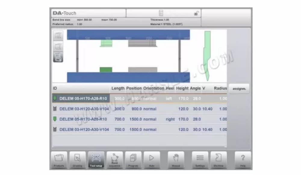
عرض المحطة لا يغير أي شيء في تفاصيل الأداة.
تسلسل الانحناء
⒈ المقدمة
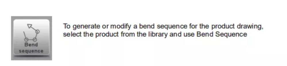
عند توفر تهيئة الأداة، يُمكن بدء محاكاة الانحناء لتحديد تسلسل انحناء للمنتج النشط. يبدأ تحديد تسلسل الانحناء بالنقر على زر التنقل "تسلسل الانحناء".
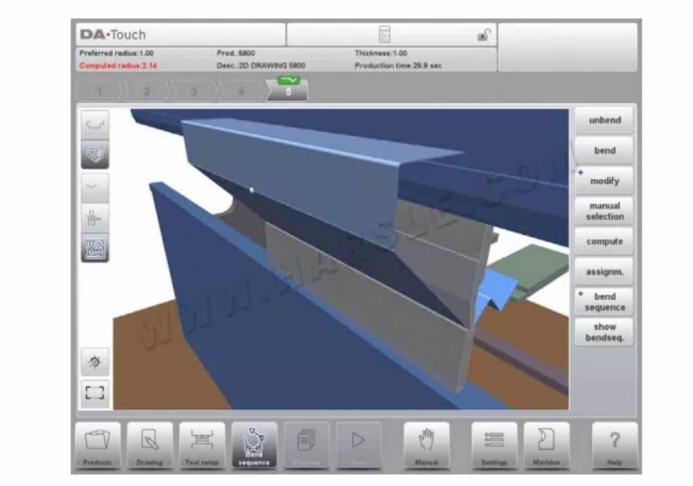
يمكن تحديد تسلسل الانحناء بالحساب التلقائي بدءًا من حاصل الانحناء. كما يمكن تحديد التسلسل يدويًا بدءًا من حاصل الانحناء، دون الحاجة إلى الحساب التلقائي.
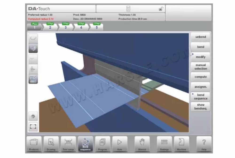
في شاشة تسلسل الانحناء، يظهر المنتج بين الأدوات في آخر موضع انحناء محتمل. عند بدء المحاكاة، يظهر المنتج في حالته النهائية. للحصول على تسلسل انحناء، يجب فتح المنتج من آخر انحناء إلى أول انحناء. يمكن القيام بذلك باستخدام مفاتيح الوظائف المتاحة.
عندما يكون من المفضل البدء بمنتج غير مطوي لاختيار تسلسل الانحناء يدويًا، يمكن اختيار ذلك من خلال زر الأمر Bend Sequence.
⑴عرض التحديد
من الممكن تبديل طرق العرض داخل شاشة النتيجة حسب الاختيار المطلوب. توجد وظائف العرض مقابل أزرار الأوامر في الشاشة الرئيسية.
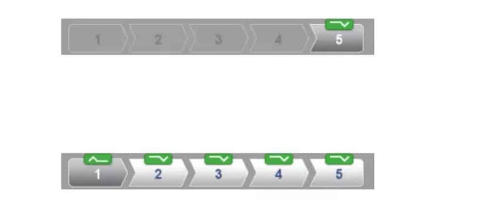
⑵ محدد الانحناء
ضمن شاشة تسلسل الانحناءات، يُمكن اختيار الانحناءات والتنقل خلالها باستخدام مُحدد الانحناءات. في أعلى الشاشة، يُشار إلى عدد الانحناءات باستخدام مُحددات الانحناءات الأولية. بعد إكمال تسلسل الانحناءات، تصبح جميعها ملونة وفعّالة، ويُظهر مؤشر انعطاف.
بعد ذلك، يُمكنك النقر على المنعطفات بسهولة لاختيار بيانات المنعطف المطلوبة. في مُحدِّد المنعطفات، سيُعرَض مؤشر الانعطاف بألوان الأخضر والأصفر والأحمر للإشارة إلى مدى الالتزام بتسلسل المنعطفات.
⒉ فك المنتج
لإنشاء برنامج CNC، يجب معرفة تسلسل الانحناء. هناك طريقتان لتحقيق ذلك:
اضغط على مفتاح الوظيفة "حساب". سيقوم جهاز التحكم تلقائيًا بحساب أسرع تسلسل ثني ممكن لهذا المنتج.
• اضغط على مفتاح الوظيفة "فك الانحناء" بشكل متكرر، حتى يصبح المنتج غير منحني تمامًا.
عندما يصبح المنتج غير قابل للثني تمامًا، اضغط على وظيفة تسلسل الانحناء ثم على زر الحفظ لإنشاء برنامج CNC وحفظه.
من الممكن ألا يتم العثور على تسلسل الانحناء لأسباب مختلفة:
• الأدوات المُثبّتة غير صحيحة. ارجع إلى قائمة إعدادات الأداة لتغيير إعداداتها.
• الواجبات غير صحيحة. ارجع إلى قائمة الواجبات لتعديلها.
تم رصد تصادم أثناء فك الانحناء. يُمكن ضبط تسلسل الانحناء يدويًا باستخدام الوظائف المتاحة. سيتم شرح ذلك في الأقسام التالية.
⒊ الاختيار اليدوي للانحناءات
عادةً ما يقترح عنصر التحكم الانحناء التالي (أو غير التالي) في التسلسل. يتم حساب ذلك بواسطة عنصر التحكم بناءً على التخصيصات المبرمجة، وبالطبع شكل المنتج والأدوات المستخدمة. لأسباب مختلفة، قد يلزم اختيار خط انحناء آخر لتسلسل الانحناء. يمكن تغيير/تحديد تسلسل الانحناء من خلال وظيفة "التحديد اليدوي". عند اختيار وظيفة "التحديد اليدوي"، تُفتح نافذة جديدة.
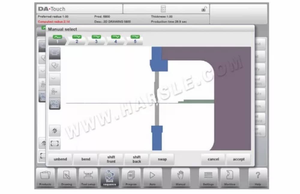
الوظائف
استقام
قم بفك الانحناء الموضح حاليًا أو ابدأ في البحث عن الانحناء المحتمل التالي لفتحه.
يلوي
ثني المنتج في شاشة المحاكاة أو التبديل إلى خطوة الثني التالية
التحول الأمامي
انقل المنتج إلى الأمام.
التحول للخلف
انقل المنتج إلى الخلف.
تبديل
قم بتدوير المنتج بين الأدوات (من الخلف إلى الأمام).
يلغي
اترك الشاشة الحالية دون حفظ التغييرات.
⑴تحويل المنتج
في قائمة محاكاة الانحناء، يحسب عنصر التحكم الانحناء التالي الممكن لفكه. يُوضع المنتج بين الأدوات، بحيث لا يحدث أي تصادم مع الأدوات أو الآلة. في حال رغبتك في تحريك المنتج أسفل مجموعة الأدوات (المثبتة)، يمكنك تحريكه باختيار وظيفة "تحريك المنتج". ستظهر نافذة جديدة.
⑵مقياس ناقل الحركة
يحسب نظام التحكم تلقائيًا مواقع المحاور X وR وZ عند كل انحناءة. ويأخذ في الاعتبار قيم تعيينات الخيارات، ويبحث عن حل دون تصادم الأصابع مع المنتج. لاختيار مواقع بديلة، يمكنك تحريك الأصابع يدويًا.
بعد فك ثني المنتج، اختر "مقياس التحويل". ستظهر نافذة منبثقة تعرض أصابع المقياس الخلفي، مع تمييز أحد الأصابع.
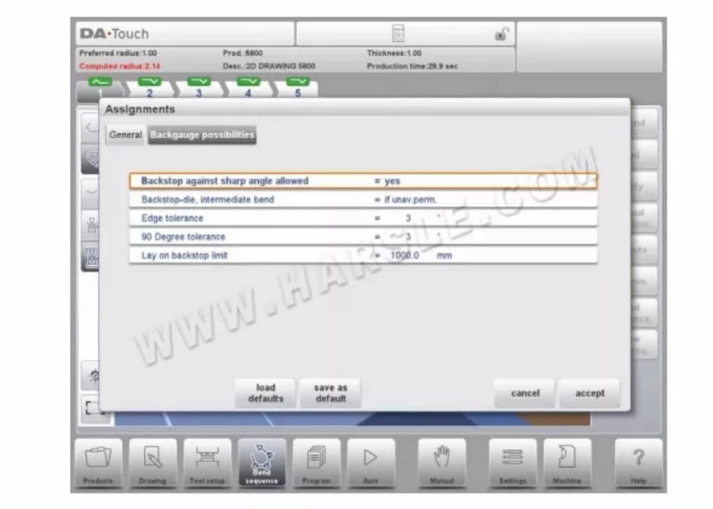
⒋المهام
⑴ المقدمة
التعيينات هي المعلمات التي يتم من خلالها التحكم في حساب تسلسل الانحناء. يتم فتح شاشة التعيينات من شاشة تكوين الأداة باستخدام مفتاح الوظيفة Assignm.
يعمل حساب تسلسل الانحناء التلقائي مع عدة شروط لإيجاد أفضل قيمة بين الحد الأدنى لوقت الإنتاج، وإمكانيات المناولة دون تصادم المنتج/الآلة، والمنتج/الأداة. لإيجاد أحد هذه الشروط، يجب برمجة عدة معاملات حسابية لحساب تسلسل الانحناء. بعض هذه المعاملات متعلق بالآلة، وبعضها الآخر يتعلق بدقة المنتج، وإمكانيات المناولة، وأوقات الدوران.
⑵المهام - عامة
درجة التحسين
المدى 1-5.
يجب إدخال عدد البدائل التي سيتم حسابها لكل منحنى هنا.
كلما ارتفع هذا الرقم، زاد عدد البدائل التي يتعين على عنصر التحكم فحصها، وبالتالي سيستغرق وقت الحوسبة وقتًا أطول:
1- أقل قدر من التحسين، وأسرع عملية حسابية
2- تحسين منخفض، حساب سريع
3- تحسين المتوسط، الحوسبة المتوسطة
4- تحسين عالي، حساب بطيء
5 - أعلى تحسين، أبطأ حساب
نسبة الامتداد الأمامي
المدى 0.01 – 1.0.
هذه هي نسبة الحد الأدنى المسموح به لطول منتجك أمام المكبس إلى الطول الإجمالي للقطعة الخام. يجب أن يكون لديك حد أدنى لطول منتجك أمام المكبس لتتمكن من التعامل معه.
⑶المهام - إمكانيات القياس الخلفي

إظهار تسلسل الانحناء
عند الضغط على وظيفة إظهار تسلسل الانحناء، يتم عرض نظرة عامة رسومية لتسلسل الانحناء.

يمكن تفعيل هذا الخيار في أي وقت بعد إجراء أول عملية فك انحناء. تعرض النظرة العامة الرسومية الانحناءات المحددة، بالإضافة إلى الانحناءات غير المحددة (علامة الاستفهام).
يمكن تكبير أو تصغير كل صورة في العرض العام بشكل منفصل باستخدام الوظائف المتاحة. كما يمكن تدوير الصور بحركة الأصابع.
برمجة المنتج
⒈مقدمة

لتحرير برنامج CNC موجود، حدد منتجًا من قائمة المنتجات، ثم انقر على زر التنقل "برنامج". عند بدء برنامج جديد، اختر "برنامج جديد"، وبعد إدخال خصائص المنتج الرئيسية، سينتقل النظام تلقائيًا إلى "برنامج".
في كلتا الحالتين، ستظهر الشاشة الموضحة أعلاه. تتم برمجة البيانات وتغييرها بنفس الطريقة في كلا الوضعين.
الوظائف
نسخ المنتجمقطعي
انسخ المنتج الحالي. عند الضغط عليه، يجب إدخال معرف منتج جديد لبرنامج النسخ.
تغيير الدليل
اختر موقعًا آخر (مجلدًا) على القرص المحلي لتخزين المنتج الحالي. سيتم نسخ المنتج تلقائيًا إلى الموقع الجديد.
تحرير الملاحظات
يفتح نافذة لعرض وتحرير الملاحظات حول المنتج الحالي. للمزيد من المعلومات حول تحرير الملاحظات، يُرجى مراجعة هذه الفقرة.
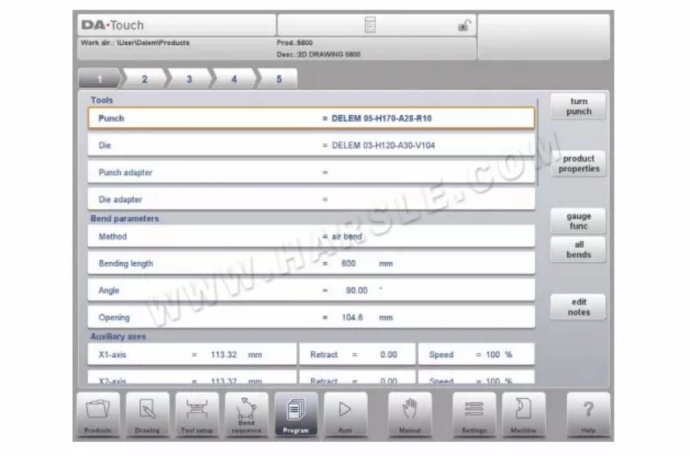
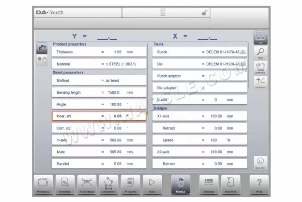
⒉ معلمات الانحناء
مُعاملات كل انحناء مُدرجة في صفحة واحدة، ويمكن تصفحها. أدناه، ستجد شرحًا لمُعاملات الانحناء المُحددة.

يتم عرض معرف المنتج ووصف المنتج في الصف العلوي على الشاشة.
أدوات
لكمة
اسم (معرّف) اللكمة المحددة. انقر للتعديل أو التحديد من مكتبة اللكمات.
يموت
اسم (معرّف) النرد المحدد. انقر للتعديل أو التحديد من مكتبة النرد.
محول اللكمة
اسم (معرّف) مُحوّل اللكمة المُختار. انقر للتعديل أو اختر من مكتبة مُحوّل اللكمة. تعتمد إمكانية برمجة المُحوّل على مُعامل "استخدام مُحوّل اللكمة" في وضع الآلة.
محول القالب
اسم (معرّف) مُحوِّل القالب المُختار. انقر للتعديل أو اختر من مكتبة مُحوِّل القالب. تعتمد إمكانية برمجة المُحوِّل على مُعامل "استخدام مُحوِّل القالب" في وضع الآلة.
برمج مُعرِّف الأداة المطلوبة أو اضغط عليها للاطلاع على الأدوات المتاحة في المكتبة. اضغط على زر "تدوير اللكمة" أو "تدوير القالب" لتغيير اتجاه الأداة (أي تدويرها).
لكمة الدوران / قالب الدوران
اقلب الأداة المُطبّقة (من الخلف إلى الأمام). متاح فقط عند وضع المؤشر على مُعامل أداة.
⒊وظائف الانحناء
يمكن برمجة الوظائف المساعدة للانحناء من خلال التمرير لأسفل صفحة معلمات الانحناء.
صامت
نقطة التسلسل التي يتحول عندها المحور Y من سرعة إغلاق سريعة إلى سرعة ضغط. القيمة المبرمجة هنا هي مسافة نقطة كتم الصوت فوق الورقة. افتراضيًا، تُستخدم قيمة كتم الصوت من القالب المبرمج. يعتمد وجود هذه المعلمة من عدمه على إعدادات الآلة.
التوازي
الفرق بين أسطوانة الجانب الأيمن والأيسر (Y1 وY2). عند القيمة الموجبة، يكون الجانب الأيمن أقل. عند القيمة السالبة، يكون الجانب الأيمن أعلى. القيمة المبرمجة نشطة أسفل نقطة التثبيت.
⒋ملاحظات التحرير الخاصة
بعد تغيير بيانات البرنامج، لن يقوم عنصر التحكم بالحساب تلقائيًا:
1 قوة
2 تخفيف الضغط
3 ضبط جهاز التتويج
إزاحة موضع المحور Z الأربعة
تصحيح موضع المحور X الخمسة
سيتم إعادة حساب المعلمات من 1 إلى 4 تلقائيًا فقط إذا تم تمكين معلمة تحرير الحسابات التلقائية (انظر وضع الإعدادات).
يُعاد حساب المعامل 5 تلقائيًا فقط عند تفعيل معامل جدول بدل الانحناء النشط (انظر وضع الإعدادات). يمكن تعديل التصحيحات على موضع المحور السيني باستخدام معاملي Corr.X (لكل انحناء) وG-corr.X (لجميع انحناءات البرنامج النشط) في الوضع التلقائي.
هناك استثناء واحد:
عندما يتم تغيير معلمة طريقة الانحناء، سيتم ضبط القوة وإزالة الضغط تلقائيًا.
الوضع التلقائي
⒈ المقدمة
في الوضع التلقائي مع تفعيل البرنامج، يمكن بدء الإنتاج. بعد تفعيل الوضع التلقائي، اضغط على زر البدء لبدء الإنتاج.
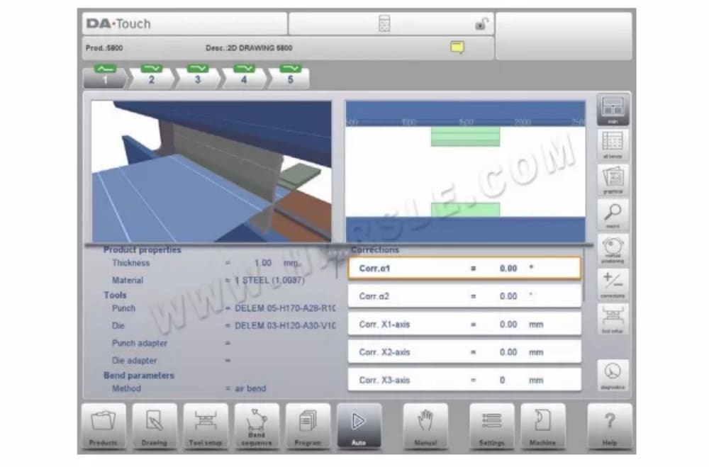
يُنفِّذ الوضع التلقائي البرنامج تلقائيًا بعد الضغط على زر البدء. عند اختيار منتج مختلف في وضع المنتجات، وهو موجود في المكتبة ومُستخدَم في الإنتاج، يُمكنك التبديل فورًا إلى الوضع التلقائي وبدء الإنتاج. في كل مرة تختار فيها برنامج ثني مختلف، يجب عليك التحقق من أدواتك ومواضعها في جهازك. يُشار إلى ذلك أيضًا برسالة تحذير "تحقق من الأدوات" عند دخول الوضع التلقائي.
في أعلى شاشة الوضع التلقائي، يُعرض المنتج المحدد مع وصفه. في أعلى الشاشة، يُظهر مُحدد الانحناءات المتاحة في البرنامج. بالضغط على الانحناء المُفضّل، يُمكن تحديد الانحناء. يُمكن الضغط على زر البدء للبدء من هذا الانحناء. تُعرض تفاصيل الانحناء المُختار في العروض المُتاحة.
⑴ الوضع التلقائي، شرح المعلمات
فيما يلي قائمة بالمعلمات المتوفرة في الوضع التلقائي.
⑵أوضاع العرض
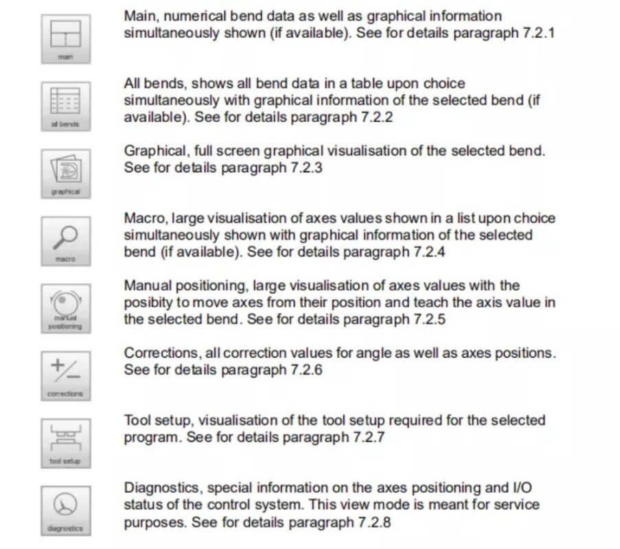
توفر شاشة الوضع التلقائي مجموعة متنوعة من طرق العرض، والتي يمكن اختيارها حسب طريقة الإنتاج. عند اختيار الوضع التلقائي لأول مرة، ستظهر الشاشة الرئيسية. على يمين الشاشة، يمكنك اختيار طرق العرض المتاحة.
أوضاع العرض التالية متاحة:
⒊ملاحظات
يمكن عرض الملاحظات التي يمكن إضافتها إلى منتج أو برنامج في الوضع التلقائي. مع وجود مؤشر الملاحظات، يُشار إلى أنه تمت إضافة ملاحظات إلى هذا المنتج، وعند النقر على المؤشر سيتم عرضها.
يمكن إضافة ملاحظات عامة إلى منتج أو برنامج، وكذلك إلى ملفات محددة. يمكن أيضًا تضمين مستندات PDF داخل الملاحظات. سيؤدي الضغط على زر PDF إلى فتح المستند.

⒋تصحيح الاصطدام
في حالة تحديد انحناءة ارتطام، يُمكن إدخال تصحيح عام لها. تُفعّل هذه الوظيفة عند وضع المؤشر على مُعامل تصحيح الزاوية ('corr. α1/α2'). لا تتوفر هذه الوظيفة إلا في حال تحميل منتج يحتوي على انحناءة ارتطام. مع 'Bumping Corr.'، تظهر نافذة جديدة يُمكن من خلالها إدخال التصحيح.

عند تغيير التصحيح العام لزاوية ما، يُعاد حساب جميع التصحيحات الفردية. وعند تغيير أيٍّ من التصحيحات الفردية، يُعاد حساب التصحيح العام.
يمكن برمجة تصحيحات الارتطام بشكل مستقل لكلا الجانبين، α1 وα2. عند تغيير التصحيح العام α1، يُنسخ تلقائيًا إلى α2، ونتيجةً لذلك، تُعاد حساب جميع تصحيحات α2 المنفصلة. لتغيير قيم تصحيح α2، استخدم التصحيح α2 أو أحد تصحيحاته المنفصلة.
الوضع اليدوي
⒈ المقدمة
في الوضع اليدوي، يمكنك برمجة معلمات انحناء واحد. هذا الوضع مفيد للاختبار والمعايرة والانحناءات الفردية.
الوضع اليدوي مستقل عن الوضع التلقائي ويمكن برمجته بشكل مستقل عن البرامج الموجودة في الذاكرة.
في أعلى شاشة الوضع اليدوي، ستجد موضع المحور الصادي والموضع الحالي للمحور السيني الرئيسي. جميع المحاور والوظائف الأخرى مُدرجة واحدة تلو الأخرى في العمودين أدناه.
عندما يتم تسليط الضوء على قيمة المحور Y أو قيمة المحور X فإن هذا يعني أنه تم العثور على علامات المرجع لهذه المحاور وتم وضعها بشكل صحيح بالإشارة إلى قيمها المبرمجة.
⒉ معلمات البرمجة والعروض
يمكن برمجة المعلمات في الوضع اليدوي واحدة تلو الأخرى. ويمكن حساب تأثير المعلمة على المعلمات الأخرى إما تلقائيًا أو يدويًا. ويعتمد ذلك على الوضع المحدد على الجانب الأيسر من الشاشة. يتيح مفتاح الحساب التلقائي
اختر بين:
يتم تصور العلاقة بين المعلمات باستخدام رمز ولون الخلفية.
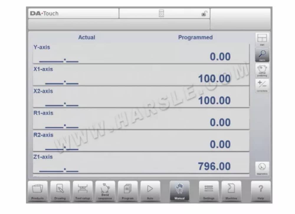
⒊ ماكرو
باستخدام الماكرو، ينتقل عنصر التحكم إلى عرض جديد يعرض قيم المحاور الكبيرة فقط على الشاشة. يمكن استخدام هذا العرض عند العمل بعيدًا قليلاً عن عنصر التحكم، مع إمكانية قراءة قيم المحاور.
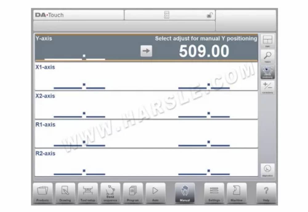
⒋ الحركة اليدوية للمحاور
⑴ إجراء الحركة
لتحريك محور إلى موضع محدد يدويًا، يمكن استخدام عجلة اليد في اللوحة الأمامية لوحدة التحكم. بعد النقر على "وضع يدوي" في الشاشة الرئيسية للوضع اليدوي، تظهر الشاشة التالية:
⒌التصحيحات
في وضع العرض هذا، تُعرض تصحيحات الانحناء المُبرمجة في الوضع اليدوي. ولأن هذا الانحناء دائمًا ما يكون انحناءً واحدًا، فسيتم عرض خط واحد.
يمكن التحقق من التصحيحات المبرمجة هنا، على غرار التصحيحات في الوضع التلقائي. كما يمكن مراقبة إدخالات قاعدة بيانات التصحيحات والتصحيح الأولي في هذه الشاشة. ونظرًا لتأثيرها الكبير على نتيجة الانحناء، يمكن استخدام الوصول إلى قاعدة البيانات للتعديل. كما يمكن أن يكون هذا مفيدًا عند البحث عن التصحيحات المناسبة باستخدام اختبار الانحناء وتخزين النتائج في قاعدة البيانات.
⒍التشخيصات
عند النقر على "التشخيصات"، ينتقل عنصر التحكم إلى عرض جديد يعرض حالة المحاور. في هذه النافذة، يمكنك الاطلاع على الحالة الحالية للمحاور المتاحة. كما يمكن تفعيل هذه الشاشة أثناء تشغيل عنصر التحكم، مما يسمح بمراقبة أداء عنصر التحكم.
أثناء دورة الانحناء.

إعدادات
⒈ المقدمة

يتيح وضع الإعدادات للتحكم، والذي يمكن العثور عليه في لوحة التنقل، الوصول إلى جميع أنواع الإعدادات التي تؤثر على برمجة المنتجات والبرامج الجديدة. ويمكن تعيين القيم الافتراضية والقيود المحددة.
تُقسّم الإعدادات إلى عدة علامات تبويب تُنظّم المواضيع المختلفة منطقيًا. في الأقسام التالية، تُناقش علامات التبويب المتاحة والإعدادات المُفصّلة.
يمكن التنقل بين علامات التبويب بمجرد النقر عليها واختيار العنصر المطلوب تعديله. ونظرًا لكثرة علامات التبويب التي يمكن للشاشة عرضها في عرض واحد، فإن سحب علامات التبويب أفقيًا يُتيح عرض جميع علامات التبويب المتاحة وتحديدها.
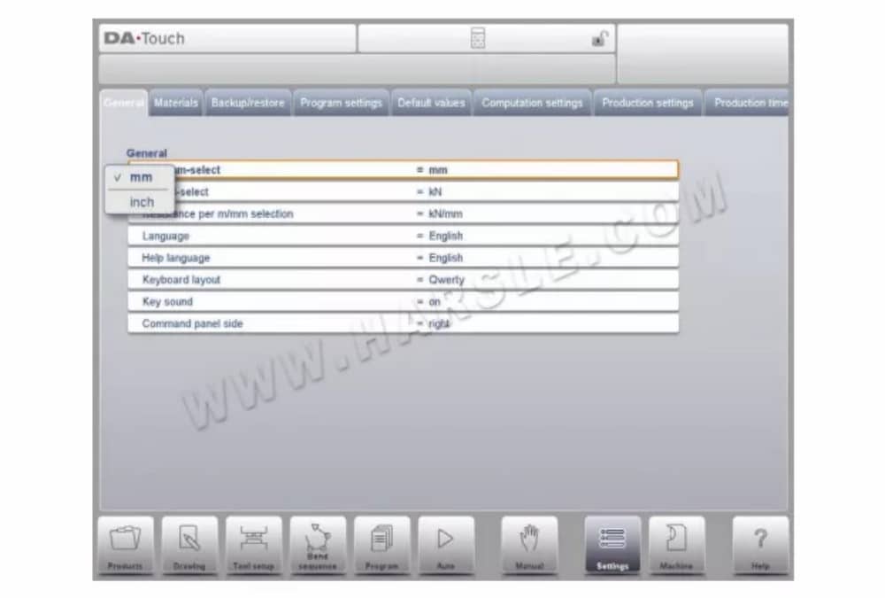
⒉عام
حدد علامة التبويب المطلوبة وانقر على المعلمة المراد تغييرها. عندما تكون المعلمات ذات قيمة رقمية أو أبجدية، ستظهر لوحة المفاتيح لإدخال القيمة المطلوبة. عند اختيار الإعداد أو المعلمة من قائمة، ستظهر القائمة ويمكن تحديدها.
يتم ذلك بالضغط. القوائم الأطول تسمح بالتمرير عموديًا للتحقق من العناصر المتاحة.
⒊المواد
في هذه التبويبة، يُمكن برمجة المواد وخصائصها. يُمكن تعديل المواد الموجودة، وإضافة مواد جديدة، أو حذف مواد موجودة. يُمكن برمجة 99 مادة كحد أقصى على وحدة التحكم.
⒋النسخ الاحتياطي / الاستعادة
تتيح هذه علامة التبويب إمكانية النسخ الاحتياطي واستعادة المنتجات والأدوات، بالإضافة إلى الإعدادات والجداول. عند استخدام المنتجات أو الأدوات من نماذج تحكم قديمة، تتوفر هنا أيضًا وظيفة استيراد لكلٍّ منها. يمكن نسخ الأدوات والمنتجات احتياطيًا واستعادتها وفقًا للإجراءات التالية. تتشابه إجراءات حفظ أو قراءة البيانات لجميع أنواع وسائط النسخ الاحتياطي: مثل الشبكة أو ذاكرة USB.

⒌إعدادات البرنامج
قاعدة بيانات تصحيح الزاوية
معلمة لتمكين قاعدة البيانات باستخدام تصحيحات الزاوية.
يتم إدخال تصحيحات الزاوية في وضع الإنتاج (الوضع التلقائي). تُخزَّن هذه التصحيحات في برنامج المنتج.
تتيح قاعدة بيانات تصحيح الزوايا تخزين هذه التصحيحات في قاعدة بيانات. وبهذه الطريقة، تبقى التصحيحات المُدخلة سابقًا لانحناءات معينة متاحة للاستخدام مستقبلًا في منتجات أخرى. عند تفعيل هذا الإعداد، يتحقق نظام التحكم أثناء الإنتاج من وجود تصحيحات لانحناءات مماثلة في قاعدة البيانات. في حال توفر تصحيحات لانحناءات معينة، فسيتم عرضها. في حالات أخرى، يمكن استيفاء التصحيحات وعرضها. يتم تعديل قاعدة بيانات التصحيحات بإدخال تصحيحات جديدة أثناء الإنتاج.
عندما يتم تمكين قاعدة البيانات باستخدام هذه المعلمة، سيتم تخزين كافة التصحيحات الجديدة المدخلة في قاعدة البيانات.
عند البحث عن انحناءات مشابهة، يبحث عنصر التحكم عن انحناءات لها نفس خصائص الانحناء النشط. تتم مقارنة خصائص الانحناء التالية:
• خصائص المواد
• سمك
• فتح القالب
• نصف قطر القالب
• نصف قطر اللكمة
• زاوية
⒍القيم الافتراضية

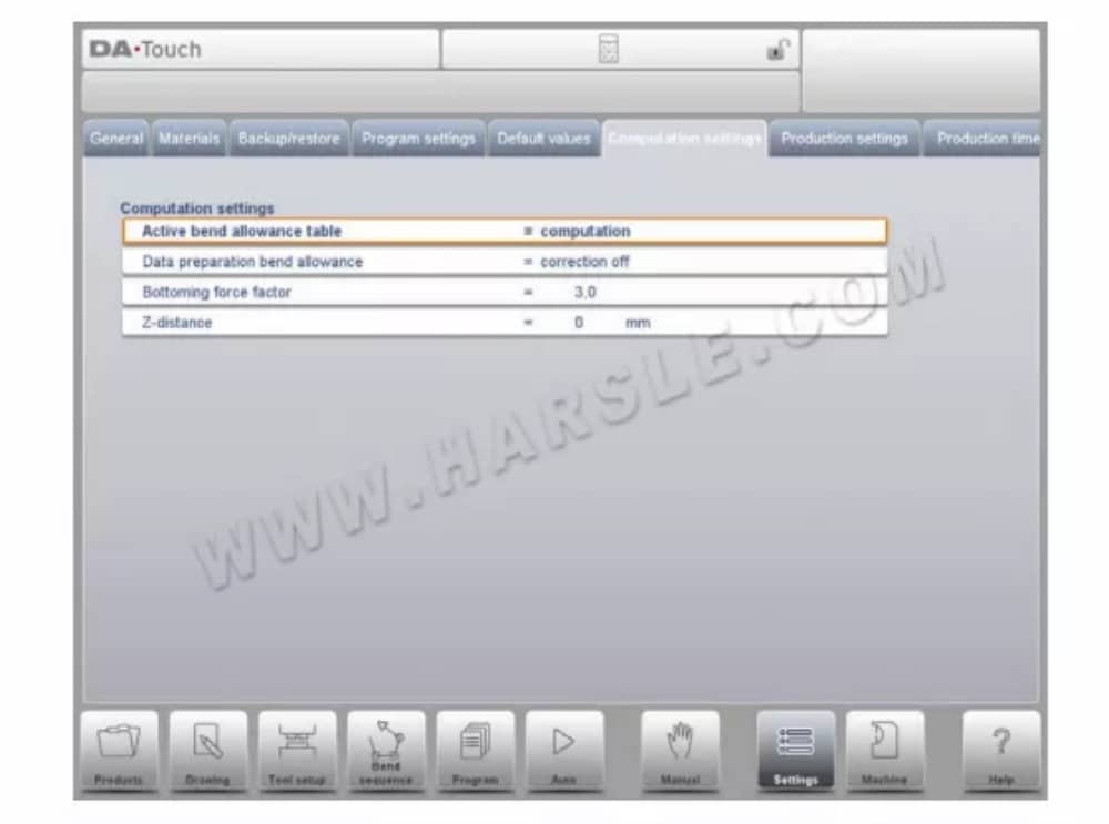
⒎إعدادات الحساب
⒏إعدادات الإنتاج
وضع عد المخزون
إعداد عداد المخزون في وضع الإنتاج، لجعل عداد المخزون (عداد المنتج) يحسب تصاعديًا أو تنازليًا.
عند اختيار العد التنازلي، ينخفض عداد المخزون في وضع الإنتاج بعد كل دورة إنتاج. عند وصول العداد إلى الصفر، يتوقف التحكم. في عملية البدء التالية، تُعاد قيمة عداد المخزون إلى قيمتها الأصلية.
عند اختيار العد التصاعدي، يزداد العداد بعد كل دورة إنتاج. يمكن استخدام العد التنازلي عند الحاجة إلى إنتاج حصة مُخطط لها مسبقًا. كما يمكن استخدام العد التصاعدي لإعداد تقرير عن تقدم الإنتاج.
⒐حساب وقت الإنتاج
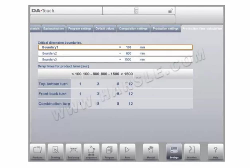
تُستخدم المعلمات في هذه الصفحة لحساب وقت إنتاج المنتج في عملية حساب تسلسل الانحناء. يعتمد هذا الوقت على سرعة وضع المحاور وأوقات مناولة المنتج. وتعتمد سرعة وضع المحاور على إعدادات الماكينة.
يستغرق التعامل اليدوي وقلب المنتج وقتًا للإنتاج. يعتمد هذا الوقت على طول المنتج وعرضه.
بالنسبة لمنتج صغير نسبيًا (في اتجاه Z)، يمكن إجراء دورة من الأعلى إلى الأسفل بسرعة.
لكن المنتج الصغير نسبيًا والذي يكون طويلًا (في اتجاه X) يحتاج إلى وقت أطول للتحول من الأمام إلى الخلف أو في دورة مركبة.
يمكن ضبط وقت الدوران بالثواني في جدول. لهذا الغرض، توجد أربع فترات زمنية (ثلاثة حدود)، ولكل منها وقت دوران محدد حسب نوع الدوران. وكما هو الحال مع أوقات الدوران، يمكنك أيضًا ضبط حدود الطول.
⒑إعدادات الوقت

وقت العرض
عرض التاريخ والوقت على لوحة العنوان، أو الوقت فقط أو لا يوجد وقت على الإطلاق.
تنسيق الوقت
عرض الوقت بتنسيق 24 ساعة أو 12 ساعة.
تنسيق التاريخ
عرض التاريخ بالتنسيق dd-mm-yyyy أو mm-dd-yyyy أو yyyy-mm-dd.
ضبط الوقت
لضبط التاريخ والوقت. سيؤدي ضبط التاريخ والوقت أيضًا إلى ضبط تاريخ ووقت نظام التشغيل ويندوز.
آلة
⒈ المقدمة

يتيح وضع الماكينة للتحكم، والذي يمكن العثور عليه في لوحة التنقل، الوصول إلى عناصر تكوين الماكينة وخصائص الماكينة المحددة التي تؤثر على الحسابات العامة وسلوك الماكينة.
تُقسّم الإعدادات إلى عدة علامات تبويب تُنظّم المواضيع المختلفة منطقيًا. في الأقسام التالية، تُناقش علامات التبويب المتاحة والإعدادات المُفصّلة.
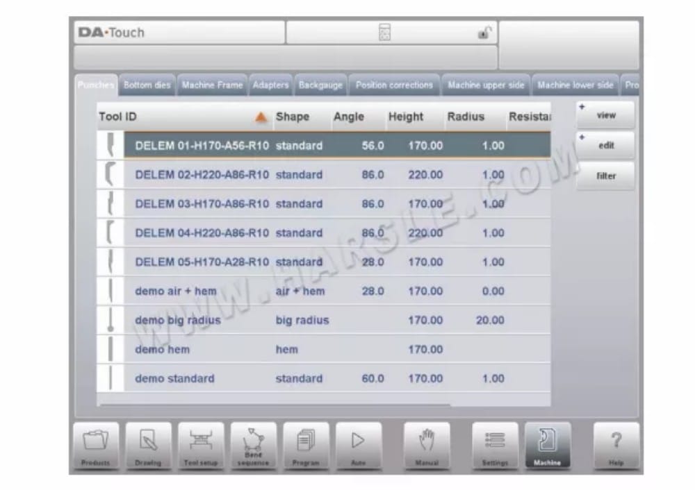
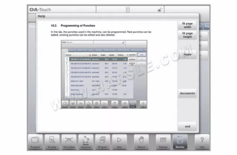
⒉برمجة اللكمات
في هذه التبويبة، يُمكن برمجة اللكمات المستخدمة في الآلة. يُمكن إضافة لقم جديدة، وتعديل اللكمات الموجودة، وحذفها.

⒊ برمجة القوالب السفلية
في هذه التبويبة، يُمكن برمجة القوالب السفلية المُستخدمة في الآلة. يُمكن إضافة قوالب جديدة، وتعديل القوالب الموجودة، وحذفها.

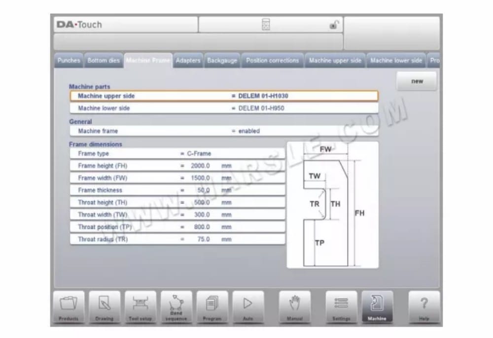
⒋إطار الآلة
في هذه التبويبة، يُمكن تحديد وضبط هندسة الآلة النشطة من العارضة العلوية والسفلية والإطارات الجانبية. كما يُمكن برمجة تعريف الآلة هنا.
بجانب الجانب العلوي والجانب السفلي للماكينة، والتي يتم اختيارها من بين المتاحة، يمكن برمجة أبعاد إطار الجانب في هذه الصفحة.
يتم عرض شكل الماكينة على شاشة المحاكاة أثناء البرمجة الرسومية ويتم استخدامها لاكتشاف الاصطدام بين قطعة العمل والماكينة.
⒌المحول
في هذه الصفحة، يمكن تمكين محولات الأدوات وبرمجتها.
عند اختيارك، يُمكنك تفعيل المحولات العلوية والسفلية. كما يُمكنك ضبط المحول الافتراضي الذي سيتم اختياره عند إضافة محول إلى إعدادات الأداة.
عند إضافة مُحوِّل، يجب تحديد المعلمات الأساسية بناءً على قالب. في المرحلة الثانية، يُمكن رسم تفاصيل المُحوِّل كأي مُثقاب أو قالب آخر.
⒍مقياس الخلفية
باستخدام أبعاد الإصبع هذه، تُؤخذ حركة المحور R وحركة المحور X المرتبطة بها في الاعتبار. كما يُحسب تصادم قطعة العمل مع المقياس الخلفي باستخدام هذه الأبعاد.
⒎تصحيحات الموضع
تصحيح موضع X
عندما لا يتوافق موضع المحور الميكانيكي الفعلي مع القيمة المعروضة، يُمكن تصحيح الموضع باستخدام هذه المعلمة. برمج الفرق المحسوب.
مثال:
- عندما تكون القيمة المبرمجة والمعروضة = 250 وقيمة الموضع الميكانيكي الفعلية = 252 فإن معامل CX = -2.
- عندما تكون القيمة المبرمجة والمعروضة = 250 وقيمة الموضع الميكانيكي الفعلية = 248 فإن معامل CX = +2.
في حالة تثبيت عدة محاور X، تتوفر معلمة منفصلة لكل محور X.
⒏الجانب العلوي للماكينة
في هذه التبويبة، يُمكن برمجة هندسة الآلة للشعاع العلوي، كملف تعريفي. تُستخدم هذه المعلومات في كشف التصادمات بين المنتج والآلة.
عند إضافة أدوات مساعدة مثلًا إلى الآلة في حالات خاصة، يُمكن برمجتها كشكل خاص للآلة لتمكين حسابات التصادم من أخذ ذلك في الاعتبار. في معظم الحالات، يكون هناك شكل واحد فقط مُبرمج.
⒐الجانب السفلي للماكينة
في هذه علامة التبويب، يمكن برمجة هندسة الماكينة للجانب السفلي (الجدول)، كملف تعريفي.
تُستخدم هذه المعلومات في كشف التصادمات بين المنتج والآلة. عند إضافة أدوات مساعدة مثلاً إلى الآلة في حالات خاصة، يُمكن برمجتها كشكل خاص للآلة لتمكين حسابات التصادم من أخذ ذلك في الاعتبار. في معظم الحالات، يكون هناك شكل واحد فقط مُبرمج.
⒑وظيفة الرسم للأدوات والمحولات وأشكال الآلات
عند برمجة اللكمات والقوالب والمحولات وأشكال الآلات، بعد البيانات الرئيسية، يوفر عنصر التحكم إمكانية رسم الشكل المطلوب بحرية في الكائن. هذه الميزة تجعل الكائنات تبدو أكثر واقعية، والأهم من ذلك، أنها تُمكّن عنصر التحكم من القيام بما يلي:
منع تصادم دقيق. في وظيفة الرسم هذه، يمكن استخدام عدة طرق للحصول على الشكل المطلوب. يمكنك رسم الشكل المطلوب، ثم تغيير المقاطع لبرمجة قيمتها الدقيقة. يمكنك أيضًا البدء بذلك من أول مقطع مرسوم، خطوة بخطوة.
ومن المهم أن تعرف ما يلي:
في النهاية، يجب إغلاق هذه الأشكال. يُمكن لخاصية الإنهاء التلقائي أن تُساعد في ذلك.
• يُستخدم ارتفاع الجسم المُبرمج في حسابات الانحناء. تذكّر
أن هذا مهم جدًا للوصول إلى النتائج المرجوة.
⒒ المنقلة
باستخدام هذه المعلمة، يمكنك تحديد جهاز قياس الزاوية الرقمي عند تثبيت الخيار OP-WPROTRACTOR.
جهاز قياس الزاوية
• غير مستخدم
• ميتوتويو 187-50x
• Mit.187-50x U-WAVE (سيتم عرض هذا الخيار فقط إذا تم اكتشاف جهاز الاستقبال اللاسلكي أثناء بدء التشغيل)
⒓ تسجيل الأحداث
⒔الصيانة
في هذه التبويبة، ستجد وظائف الصيانة. بجانب عداد ساعات الماكينة وعداد دوراتها، يمكنك أيضًا العثور على وظائف للمساعدة في استبدال الوحدات وتخزين بيانات التشخيص.

⒕ معلومات النظام
في هذه التبويبة، يمكنك العثور على معلومات النظام. إلى جانب معلومات إصدار البرنامج، يمكنك أيضًا قراءة معرفات الوحدات المُثبّتة وإصدارات الملفات الخاصة بشركة OEM.
بالإضافة إلى المعلومات، تتوفر هنا أيضًا وظيفة تحديث البرامج.
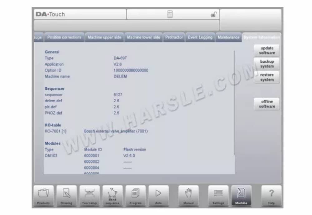
تعرض هذه الشاشة معلومات مفصلة حول نظام التحكم. هذه المعلومات مفيدة لأغراض الصيانة.
طلب
إصدار التطبيق الحالي
معرف الخيار
معرف الخيار الفريد لعنصر التحكم
المُسلسل
رقم إصدار جهاز التسلسل الجاري تشغيله
ديليم.ديف
رقم إصدار ملف delem.def الجاري تشغيله
الوحدات النمطية
الوحدات المبرمجة مع رقم تعريفها وإصدار فلاش. قد تحتوي هذه القائمة على أكثر من أربعة عناصر؛ وفي هذه الحالة، يُمكن تمرير القائمة.
تحديث البرنامج
باستخدام برنامج التحديث، يُمكن لجهاز التحكم تثبيت حزمة تحديثات البرامج من ذاكرة USB. سيساعدك متصفح الدليل على تحديد التحديث المطلوب وبدء عملية التثبيت.
نظام النسخ الاحتياطي
تُجري وظيفة النسخ الاحتياطي للنظام نسخة احتياطية كاملة للنظام على ذاكرة USB. يُكتب ملف فريد مُؤرخ على ذاكرة USB. تحتوي هذه النسخة الاحتياطية على برنامج Delem، وبيانات خاصة بشركة تصنيع المعدات الأصلية (OEM)، بالإضافة إلى ملفات المستخدم.
استعادة النظام
يمكن استخدام وظيفة استعادة النظام لاستعادة نسخة احتياطية سابقة للنظام. أثناء العملية، يمكنك تحديد ما تريد استعادته.
برامج غير متصلة بالإنترنت
تُنشئ وظيفة البرنامج غير المتصل بالإنترنت ملف إعداد للبرنامج على ذاكرة USB. يُمكن استخدام هذا الإعداد لتحديث برنامج موجود غير متصل بالإنترنت. يضمن استخدام إصدار البرنامج المتوافق مع برنامج التحكم توافقًا مثاليًا للوظائف.
دليل التشغيل
إذا كنت تريد تنزيل دليل تشغيل DELEM DA-66T لآلة ثني الثني CNC الخاصة بك بصيغة PDF، يمكنك زيارة مركز التنزيل الخاص بنا، حيث ستجد هنا جميع الأدلة التي ستحتاجها.


