Struggling to master your DELEM DA-69T prensa plegadora? This guide will help you understand the operation steps to ensure precise bending and improved productivity.
The DELEM DA-69T prensa plegadora provides advanced control features for accurate bending. Learn the step-by-step instructions for its optimal operation and how to avoid common mistakes that hinder productivity.
Now, let’s explore the setup process and key features to optimize your DELEM DA-69T press brake for seamless operations.
Descripción general del funcionamiento e introducción general
1. The control unit
El control se ve así:

La apariencia precisa de su control puede variar.
El control se opera principalmente mediante la pantalla táctil. En las siguientes secciones de este manual, se describe la función y los controles táctiles disponibles, además de las funciones específicas.
Además de los controles táctiles, la parte frontal del control consta de una parada de emergencia, el volante y los botones de inicio y parada.
Special function keys, which can be mounted in the top panel of the control, have their specific description parallel to this user manual and will be supplied by the machine manufacturer.
Este manual de usuario se centra en el software de control y las funciones relacionadas con la máquina.
2. Front control elements
The frontpanel, beside display, consists of the following control elements:

3. USB connectors

4. Operation and programming modes
The control’s main screen looks as follows:
La pantalla variará según el botón de navegación activo. La pantalla principal anterior aparecerá con la función Productos activa.
Con solo tocar los distintos modos, se seleccionará el modo específico.
La estructura de la pantalla principal es la siguiente:
Panel de título
En la parte superior, siempre se muestra el panel de título. En esta área encontrará información sobre el logotipo, el producto cargado, el directorio de productos seleccionados y (cuando esté activado) la fila de servicio. También encontrará los indicadores de la máquina.

Panel de información
En el panel de información se muestran y pueden encontrarse todas las funciones y visualizaciones relacionadas con el modo seleccionado.

Panel de comandos
El panel de comando es parte del panel de información y es la ubicación donde se pueden encontrar los controles relacionados con el panel de información.
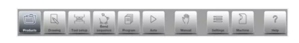
Panel de navegación
El panel de navegación es el área donde se encuentran todos los modos principales. Esta área siempre está visible. Los controles, botones grandes con iconos, permiten cambiar directamente de un modo a otro.

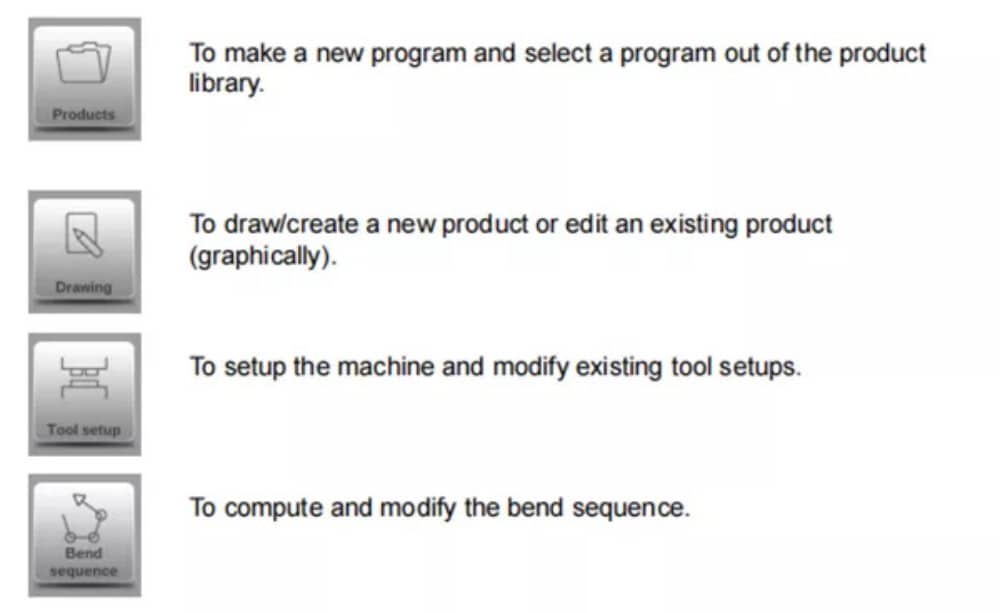
Explicación de los modos principales / botones de navegación

5. Getting started
(1)Introduction
Para obtener un programa de plegado para un producto, el control ofrece la posibilidad de crear un plano del producto y calcular una secuencia de plegado válida. Con esta información, se genera un programa de plegado.
Esto se hace con los siguientes pasos:
● Go to the Products mode in the navigation panel and start a new product by tapping New Product.
● Ingrese las propiedades del producto y comience a dibujar un perfil de producto 2D en el modo de dibujo.
● Verifique las herramientas, modifíquelas o realice una nueva configuración en el modo de configuración de herramientas.
● Use the Bend Sequence mode to determine the bend sequence by calculating it or manually modifying it upon your own idea’s.
● Cuando sea necesario, modifique el programa numérico CNC a través del modo Programa.
● Pulse Automático y presione el botón Iniciar para producir el producto programado.
(2)Preparations
Antes de poder iniciar la programación del producto, se deben realizar los siguientes preparativos.
● The correct material properties must have been programmed in the Materials library. You can find this on the Materials page in the Settings mode.
● The correct tools must be programmed in the Tool Library. Tools are necessary to create a CNC program. You can find the libraries for the different types of tools in the Machine mode.
(3)Create a drawing
The control offers the functionality to create a drawing of the intended product. With this drawing application, tap Drawing in the navigation panel, a 2D profile or 3D product drawing is created. At this stage, there is no calculation of bends or dimensions: any profile or drawing can be created.The drawing method on the Touch screen control is based on:
● Dibujo
● Value setting
Dibujo
Tanto el producto como la forma de la herramienta se pueden dibujar tocando la pantalla en las diferentes direcciones que debe tener el dibujo. La aplicación, tras tocar, dibujará una línea entre los puntos indicados. El último punto del diseño siempre mostrará un gran punto rojo.
Cuando el punto de dibujo esté en la pantalla, puede mantener el dedo en esta posición y moverlo por la pantalla para mover la línea conectada en la dirección deseada o alargarla. Este método se denomina "Arrastrar". La longitud y el ángulo se verán en la pantalla y se pueden ajustar para que sean exactos o cercanos al valor solicitado.
Configuración de valores
Once the product or tool is drawn in the Sketching method the exact values of line lengths and angles can be optimized by the Value setting method. Just tap 2 times on the value of the line length or angle to change and the keyboard will pop-up. The value can be entered in 2 ways
of confirmation:
● Entrar en la función
● Función Enter-Next
The Enter function will close the keyboard after entering the value. The Enter-Next function will enter the value on the line or angle to change and the keyboard will remain opened for the next programming step.
In case the typed value is erroneous, the “undo” button right from the input field can be tapped to return to the original value or the backspace key on the keyboard to delete the last typed character.
Función de zoom
Al juntar dos dedos en la pantalla simultáneamente, se puede ampliar y reducir la visualización del dibujo, la herramienta o la máquina. Separando los dedos, el sistema amplía la imagen; acercándolos, la reduce.
Ajustar a la pantalla
En los iconos de comando del lateral de la pantalla encontrarás la función "Ajustar a la pantalla". Esta función se puede usar cuando el tamaño del dibujo no se ve bien en la imagen. Solo tienes que pulsar una vez y el dibujo completo se ajustará a la pantalla.
Panorámica
Al tocar y arrastrar simultáneamente dos dedos por la pantalla (deslizándolos en la misma dirección), se puede desplazar el objeto en 3D. En 2D, un solo dedo también permite el desplazamiento.
Giratorio
En 3D, la rotación de la visualización del producto, herramienta o máquina, se puede realizar con un solo dedo deslizando sobre la pantalla.
Puede encontrar más información sobre esto en el capítulo 3.
Features of the drawing tool
● Graphical design of product shapes in 2D and 3D (if available)
● Scaled sheet thickness
● Auto scaling
● Horizontal and vertical projected dimensions can be entered
● Real scale tool design
● Various machine shapes (pressbeams and tables)
● Changing of lengths and angles
● Adding or deleting of bends
● Special bend features can be applied
● Hemming bends can be programmed
● Bumping bends can be used for big radius
● Existing products can be copied, changed and stored as a new product
● Closing dimension or highest precision tolerance selection
● Connecting 2D programs for 3D-production
(4) Determine bend sequence
Una vez finalizado el diseño del producto, el control ofrece el modo de configuración de herramientas para programar la configuración exacta de la herramienta tal como está organizada en la máquina. Posteriormente, puede seleccionar el modo de secuencia de plegado para determinar y simular la secuencia de plegado requerida.
En el modo Secuencia de Plegado, el control muestra el producto, la máquina y las herramientas. En este menú, se puede programar y comprobar visualmente la secuencia de plegado. Una vez determinada la secuencia de plegado, se puede generar el programa CNC.
More information about this can be found in chapters 4 and 5.
Cálculo de la secuencia de flexión
• Cálculo automático del tiempo mínimo de producción
• Determinación interactiva de la secuencia de curvatura
• Determinación manual de la secuencia de curvatura
• Visualización de colisiones del producto con herramientas y máquina.
• Selección libre de herramientas y formas de máquinas
• Asignaciones de tiempos de giro, velocidad de tope trasero, etc.
• Cálculo de longitud en blanco
• Indicación del tiempo de producción
• Simulación de secuencia de flexión
• Posiciones de dedos programables
(5) Numerical program
El menú Programa da acceso al programa numérico y a los valores del producto activo.
Hay dos posibilidades para crear un programa CNC:
• ingresar a un programa numérico, iniciado a través del modo Productos, tocar Nuevo Programa, paso a paso;
• generar el programa a partir de la simulación gráfica de curvatura iniciada a través del modo Productos, pulsar Nuevo Producto, a través del modo Dibujo. (ver: Modo Dibujo; dibujo de producto).
If the program is entered by hand, there is no collision check. All program values must be entered manually. The program depends on operator experience.
If the program is generated from a graphical bend sequence, the program can be visualised during production. A generated program can be edited according to operation needs.
Puede encontrar más información sobre esto en el capítulo 6.
When a drawing has been completed with a bend sequence, and the program is stored, the program is post processed and the numerical program becomes available.
The system automatically computes :
• Fuerza necesaria
• Ajustes de máquinas como:
• Posición del eje Y
• Descompresión
• Posición del eje X
• Retracción del eje X
• Apertura en Y
• Ejes R
• Ejes Z
Las posiciones de los ejes se calculan según la configuración de la máquina.
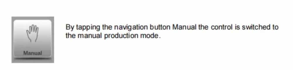
(6) The Auto menu and Manual menu, production modes
Se puede ejecutar un programa de producto mediante el modo automático. En este modo, se puede ejecutar un programa completo, plegado tras plegado. En el modo automático, se puede seleccionar el modo por pasos para iniciar cada plegado por separado.
El modo manual del control es un modo de producción independiente. En este modo, se puede programar y ejecutar un plegado. Se utiliza normalmente para probar el comportamiento del sistema de plegado.
Puede encontrar más información sobre esto en los capítulos 7 y 8.
(7) Back-up data, external storage
Tanto los archivos de producto como los de herramientas pueden almacenarse externamente. Según la configuración, estos archivos pueden almacenarse en una red o en una memoria USB. Esto facilita la copia de seguridad de datos importantes y la posibilidad de intercambiar archivos entre controles Delem.
Puede encontrar más información sobre esto en el capítulo 9.
6. Programming aids
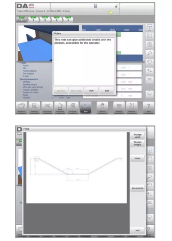
(1) Help text
Este control cuenta con una función de ayuda en línea. Al pulsar el botón de ayuda en el panel de navegación, se proporcionará ayuda contextual.
Para activar una ventana de ayuda para un parámetro, toque el botón Ayuda en el panel de navegación.
Aparece una ventana emergente con información sobre el parámetro activo.

Esta ventana de ayuda contiene la misma información que el manual de operación.
La ventana de ayuda se puede utilizar de la siguiente manera:
Puede desplazarse por el texto deslizando un dedo en la dirección deseada. Al tocar la parte inferior o superior de la pantalla, puede usar la opción "Página anterior" o "Página siguiente" para navegar por el texto de ayuda.
La función Índice facilita el acceso directo a la tabla de contenido. Los hipervínculos en la tabla facilitan la navegación directa al tema deseado.
Pulse Finalizar para cerrar la ventana de Ayuda.
(2) Listbox functionality
Varios parámetros del control tienen un número limitado de valores posibles. Al seleccionar un parámetro, al tocar la línea de parámetros en la pantalla, se abrirá la lista de opciones cerca del punto donde se tocó la línea y se podrá seleccionar el valor deseado.

To undo the selection and the opened listbox, tapping outside the box will make it close without changing the selected parameter.
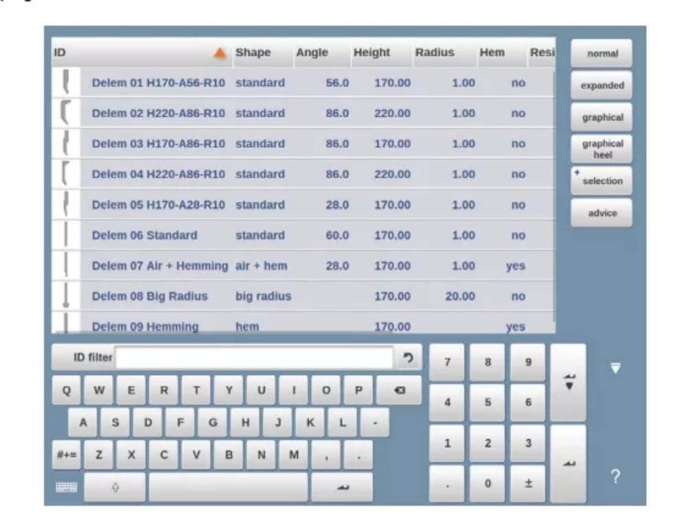
(3) Filter, live search, auto filter
En algunos modos se ofrece una lista de entidades (productos, herramientas, materiales, etc.). Un ejemplo de este menú es el modo Productos (selección de productos). Para buscar un producto o herramienta en particular, se puede usar la función de filtro. Pulse el botón de comando "Filtro" y escriba una parte del ID en el campo de entrada. Automáticamente, la lista se limita a los elementos que contienen la parte introducida.
Se pueden separar varias partes de búsqueda mediante .
To close an open filter screen use the keyboard-close button on the right side next to the keyboard.
Filtro automático
In addition to the filter function the column headers of eg. the tool selection tables and the product selection table have ‘auto-filter’ functionality.
When tapping the column header one can sort the list based on that specific column. The triangle in the header is shown as an indication of the sort order.
When tapping a header with auto-filter functionality a list box will be shown automatically offering the possible options for filtering, derived from the available entries in that column. E.g.
when using this in a die selection, the V-opening can be filtered to the desired value as searched for. The list will only show dies complying the set filter.
Filters can be switched of in a similar way. The list also offers a remove filter function.

(4) Navigation
Dentro de algunos modos, las pantallas del programa están divididas en pestañas.
The tabs can easily be selected by just tapping them. When a tab is not completely visible or not visible at all, just by dragging the tab row horizontally, the desired tab can be “pulled” in sight and be selected.
(5) Text input and editing
El cursor permite introducir un valor o texto específico dentro de una entrada existente. Simplemente toque la posición deseada. El cursor aparecerá y la entrada se añadirá allí.
E.g. in Edit notes, where multiple lines can be entered Enter is used for linefeed. Cut, Copy and Paste are offered on the keyboard for editing convenience. Undo and Redo can also be used within this editor.

The keyboard can be shown or hidden in this multiline editor using the arrow key in the lower left corner.
(6) Typing alphanumeric characters vs. special characters
Se pueden usar caracteres alfanuméricos y especiales en todo el control. Aparecerá un teclado alfanumérico completo en pantalla cuando sea necesario.
When editing a field which is pure numeric, the alphanumeric characters will be “greyed-out” and only the numerical keypad can be used. For fields which enable to use alphanumerical strings, the keyboard is completely available. Special characters as ? % – can be found using the special character button on the left-lower side of the keyboard.
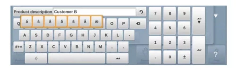
El teclado en pantalla admite caracteres especiales (como á, à, â, ã, ä, å, æ) manteniendo presionado un carácter (como 'a').
(7) Calculator
The CNC control is providing a “desktop calculator” available for the operator.
At the top of the screen the calculator icon can be used to switch to calculator functionality.
The keyboard area provides calculator functions which can be used autonomously. Standard functions (add, subtract, multiply and devide) including percentage, square root, square and memory functions are available.
In case calculations should use parameter values as an input, and results as an output, one can switch to the calculator from the parameter entry. This will bring the parameter value to the calculator, and the result back to the input line.
No cutting or pasting is necessary. Only when entering and confirming the calculated value in the parameter entry line, it will be used forward.
(8) Messages centre
When messages are displayed coming from PLC, Safety systems, LUAPs or the Sequencer, these messages can be ‘send’ to the ‘Messages centre’. When a message is displayed simultaneously the message centre symbol is shown in the top row of the page header, next to eg. the calculator and keylock symbol. When tapping this message centre symbol the messages are taken from the screen, giving way for normal programming and editing.
When tapping again the actual messages are shown.
Cuando los mensajes están en segundo plano, el símbolo del centro de mensajes tiene un indicador adicional para mostrar nuevos mensajes entrantes que aún no se muestran.
(9) Network
The CNC control is equipped with a network interface. The network function offers the operators the possibility to import product files directly from the network directories or to export the finished product files to the required network directory
Chapter 9 about backup/restore in Settings mode contains more information about networking possibilities.
(10) Keylock function
Para evitar cambios en los productos o programas, la función de bloqueo de teclas ofrece la posibilidad de bloquear el control.
Hay dos niveles de bloqueo del control: bloqueo de programa y bloqueo de máquina.
• En el bloqueo de programa, solo se puede seleccionar y ejecutar un producto en modo automático.
• En Machine Lock, la máquina se bloquea y no se puede utilizar el control.
To lock a control just tap the lock symbol in the top of the screen. Depending on the code which is used, the control will be in Program Lock or Machine Lock. Program Lock wil show a closed lock in grey. Machine lock will show the same lock but colored (red).
(11) OEM function panel
Dependiendo de la implementación del fabricante de la máquina, la esquina superior derecha de la pantalla se puede utilizar para indicadores especiales.
To access functions related to those indicators, the OEM function panel can be opened by tapping this corner of the screen.
(12) Software versions
La versión del software bajo su control se muestra en la pestaña Información del sistema en el menú Máquina.

Productos, la biblioteca de productos
1. Introduction

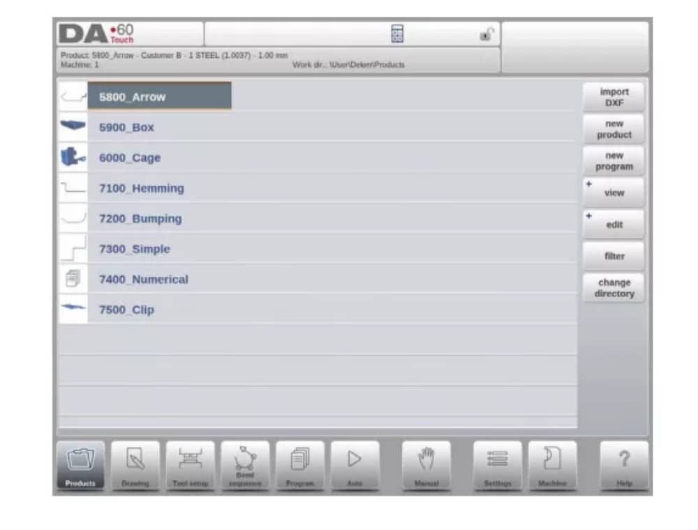
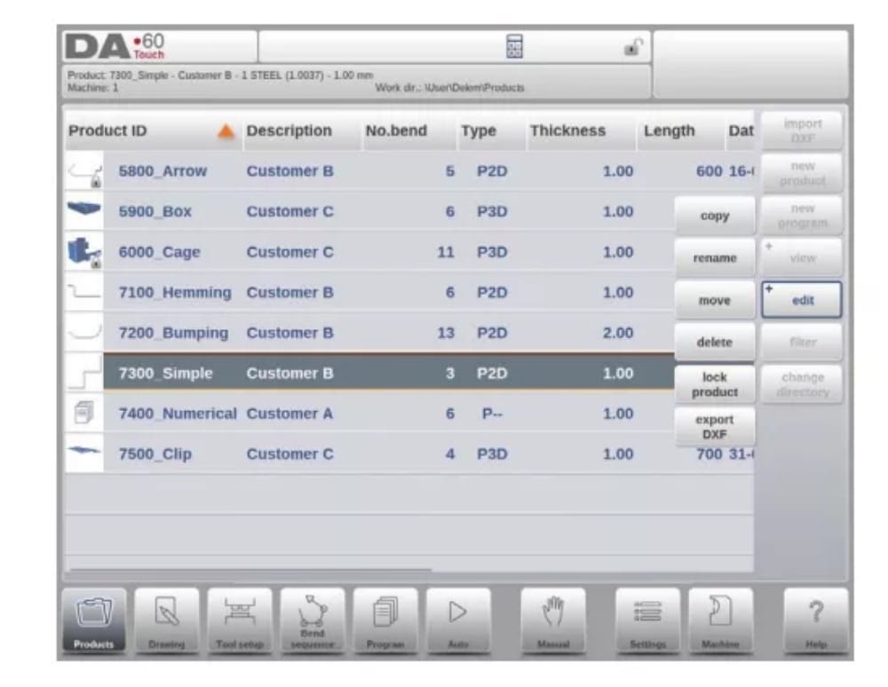
(1) The main view

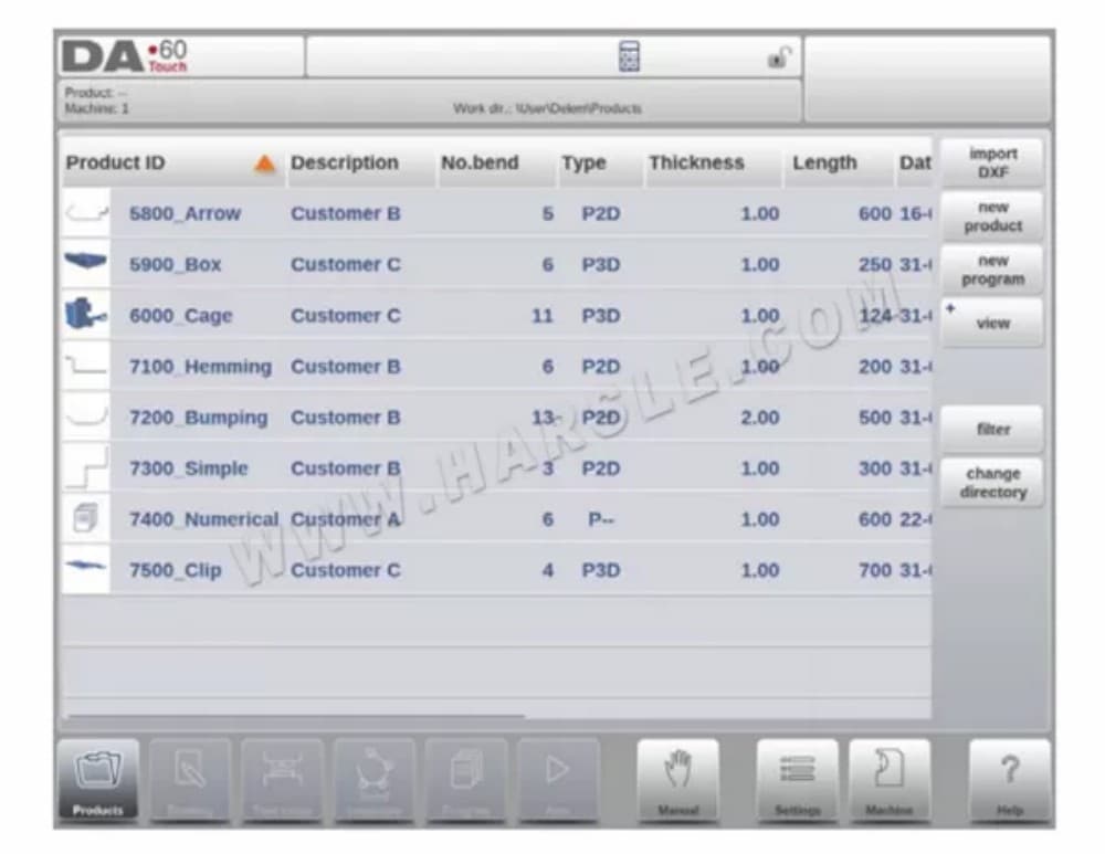
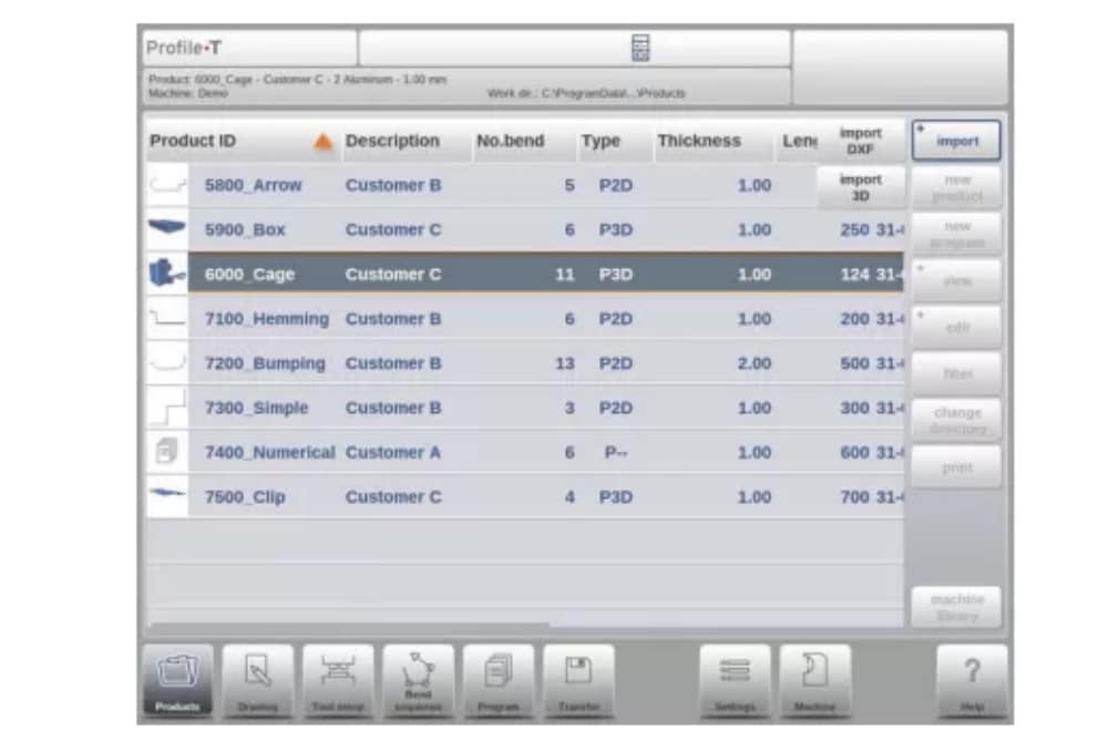
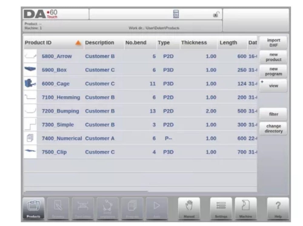
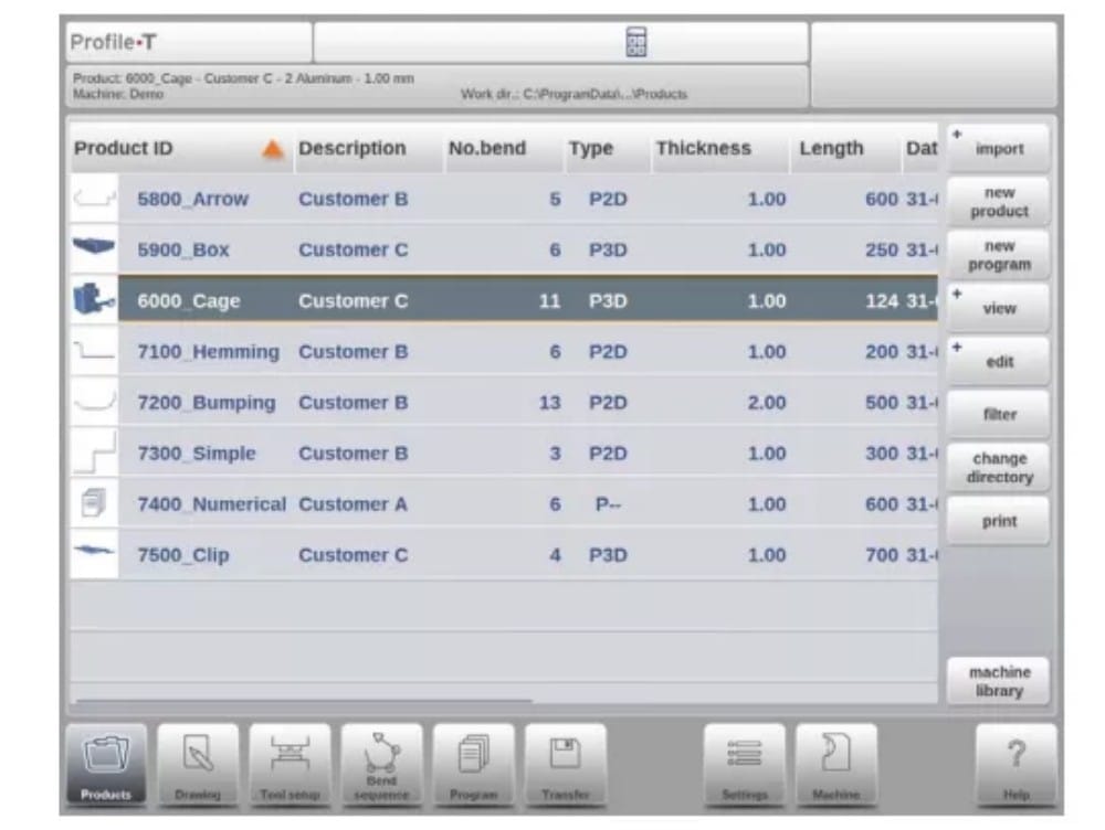
In Products mode an overview is given of the program library on the control. In this mode a product program can be selected (loaded). After that a program can be modified or executed.
Each item in the list consists of a thumbnail of the graphical product (for numerical programs a symbol is shown), its Product ID, the Product Description, the Number of bends in the product, what kind of product it is (Type) and the Date it was last used or modified.
The Type indication of the product shows following types of products:
(2) Product selection
Para seleccionar un producto, basta con un solo toque. El producto se seleccionará y se cargará en la memoria. Desde aquí, se puede iniciar la producción pulsando "Auto". También se puede navegar por el plano del producto (si existe), su configuración de herramientas, la secuencia de plegado y el programa numérico del producto.

(3) New Product, starting a new graphical product
Para iniciar un nuevo producto gráfico, toque Nuevo producto.
Después de elegir un nuevo producto, comienza la programación de un nuevo producto con sus detalles generales como ID del producto, espesor y material.

(4) New Program, starting a numerical program
Para iniciar un nuevo programa numérico, toque Nuevo programa.
Después de elegir el nuevo programa, la programación comienza con sus detalles generales, como por ejemplo ID del producto, espesor y material.

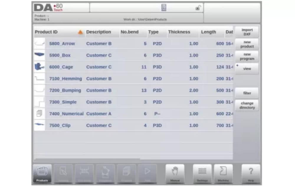
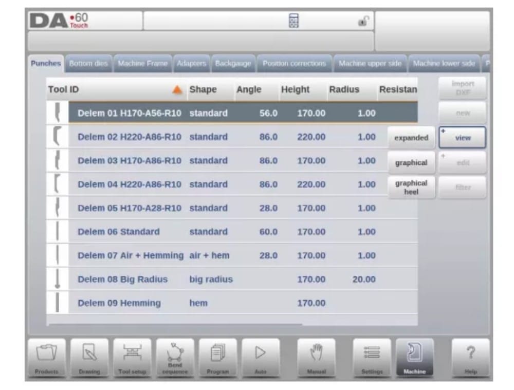
(5) Views
Para visualizar los productos como una lista simple o completamente gráfica, se puede utilizar la función Ver.
By tapping View one of the three view modes can be selected.

(6) Edit, Copying and Deleting a product or program
To delete a product in the Products mode select a product by tapping it. It will be selected.
After that tap Edit and use Delete. To finally delete it confirm the question. To delete all products and programs at once, tap Delete All.

To copy a product select a product or program and tap Edit and use Copy. After this the name of the product can be programmed and the copy will be done. The product will appear in the same directory. The copied product will be an exact copy including tool setup and bend sequence if available.

(7) Product Rename and Move
Products can also be moved and renamed.This can be done in one single step: Move moves a product to a new directory, Rename allows the user to give it a new name within the same directory.
To move or rename a product select a product or program and tap Edit and choose Move or Rename from the list. For Rename a new name can be given. The product will appear in the same directory. For move a new location can be selected. The copied product will be an exact copy including tool setup and bend sequence if available.
(8) Product Lock/Unlock
La función de bloqueo/desbloqueo del producto ofrece un método sencillo para evitar cambios accidentales en programas o productos terminados. De esta forma, los productos optimizados y en buen estado no se pueden modificar a menos que se desbloqueen.
Al tocar Editar, se puede cambiar la función Bloquear producto/Desbloquear producto para cada producto o programa.
(9) Filter function
To make finding products easier the filter function enables live searches through-out the Products mode.
Al pulsar "Filtro", se mostrará la pantalla de filtros. Al escribir la cadena de filtros deseada, opcionalmente dividida por espacios, se iniciará la búsqueda en tiempo real.
Opcionalmente, se puede seleccionar una vista diferente. También se puede cambiar la propiedad específica a la que se aplica el filtro mediante Selección.
Selections can be done on Product ID, Product Description, Type, Thickness, Length or Date.
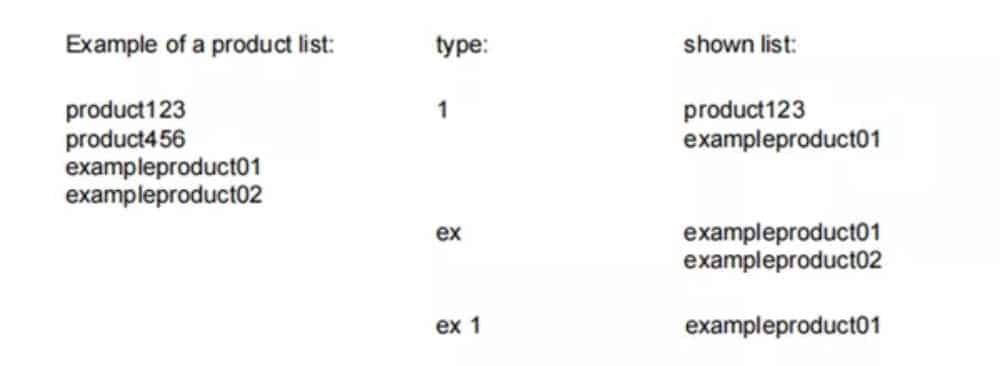
Puede introducir un nombre o número completo, o solo una parte. Si introduce parte de un nombre y esta aparece en varios nombres de productos, el control mostrará todos los nombres de productos que la contengan. También es posible introducir una combinación de nombre y número.
See also section 1.6.3 about Filtering and ‘Live search’.

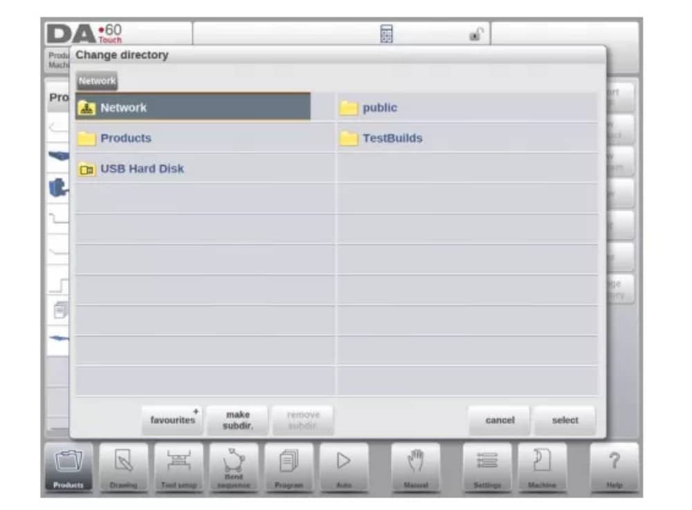
(10) Change directory
To change to a different product directory, or to add a new product directory, tap Change Directory. When an obsolete directory must be removed, select the directory and tap Remove
Directory. When a desired directory is reached, tap Select to jump back to the Products screen which will show all products in the directory. The active local directory name is displayed in the header.

(11) Network product selection
When a network directory has been mounted in the control this mounted directory can be found under Network. Network is available next to the Product directory when using change directory. The name of the mounted drive indicates availability for product selection and
almacenamiento.
Se puede navegar por los directorios de red en el explorador de directorios. Se pueden seleccionar, agregar y eliminar directorios, así como seleccionar productos. Al llegar al directorio deseado, pulse "Seleccionar" para volver a la pantalla Productos, donde se mostrarán todos los productos del directorio. El directorio de red es ahora el directorio local activo. Su nombre se muestra en el encabezado de la pantalla.
When you leave the product selection menu the control remembers the active subdirectory and the active product (if a product was selected) until another directory or product is selected.
While working with a “read-only” network, or when the network connection is interupted, the product will be saved in subdirectory “Recovered”. This can be found as a subdirectory under Products.
By tapping the Refresh button (on View) in Products mode the product library that is displayed on the screen is refreshed, which can be useful when working from a network location.
2. The DXF import option
An alternative for drawing the desired product in the control, the control can also import an externally generated CAD-system output file. This chapter will explain the use of the DXF converter to import DXF files and its functionality.
The DXF import option is started with the command button above New Product. Import DXF opens a file selection browser to select the DXF file.
Files can be located on eg. a USB stick or on the network directory. One can browse to the location and select the file.
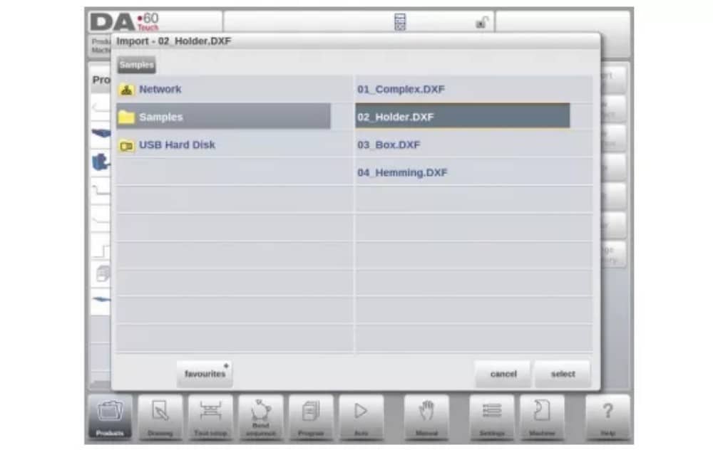
For the DXF file to be imported it is advised to create the original drawing as accurate as possible. Bend lines should be connected to contour lines to obtain an accurate product drawing. If this is not the case, the DXF Converter can correct small errors.
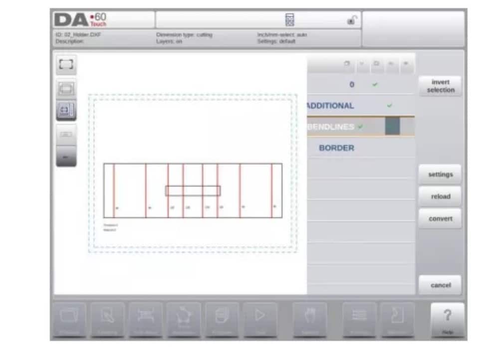
After selecting the DXF file the DXF import function window will open showing the DXF file. If this is with layer selection on, the drawing will be dashed, since no line is yet assigned to what it means.
(1) Product drawing dimensions
The drawing file can be organised in two ways:
• dimensiones de proyección;
• dimensiones de corte.
Estas formas se describen en los siguientes subpárrafos.
Durante la operación en el convertidor DXF, es posible cambiar entre dimensiones de corte y de proyección. Esto se puede hacer en la configuración de conversión DXF.
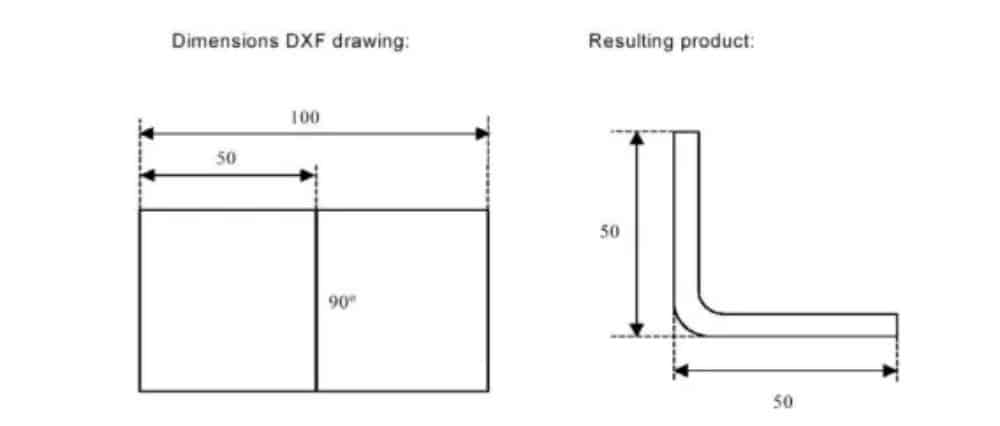
Dimensiones de proyección
In this situation all product sides and bend lines have the length of the resulting product. The drawing does not represent the real size of the sheet that must be bent, but is merely a representation of how the sheet is to be organised into bends and surfaces. When such a
drawing is loaded and converted, the converter will construct a product drawing with exactly the same sizes as are present in the original drawing. Later on additional information is added about material, sheet thickness and product dimensions. It is left to the control to create a CNC program with proper axes positions that will result in a product as intended.
(2) Bendlines and Layer selection with Line assignment
Para una conversión adecuada, es importante la asignación de propiedades específicas del producto a líneas en el DXF.
Según el contenido del DXF, las líneas de plegado, el contorno y la información de texto adicional se pueden asignar capa por capa. Si la selección de capas está desactivada, las líneas de plegado se buscan automáticamente.
Información de la línea de curvatura
Con las líneas de curvatura, la información del ángulo se puede definir mediante texto cerca de la línea. Las etiquetas de texto,
to be configured in Settings::Labels, can be used as follws:
• Default: normal air bending with a positive or negative value
• Hemming: an H followed by a positive or negative value of the pre-bend angle.
• Radio: una R seguida del valor del radio.
Definición:
• valor positivo: la brida se dobla hacia arriba,
• valor negativo: la brida se dobla hacia abajo.
Información del producto
Beside the actual product drawing a DXF drawing can contain other information, such as manufacturer name, dimension lines, product description etc. If this information is organised in other layers than the product drawing then this information can be filtered out by selecting only certain layers for conversion. Otherwise, it possible to remove unnecessary information in the converter program before conversion of the drawing is started.
Selección de capas
Depending on the DXF import settings, which can be entered from the mainscreen, layer selection can be set on or off.
In case of layer selection on, the layer property list visualisation can be switched. The buttons in the left top corner enable this choice. Following paragraphs describe the difference between
Layer selection switched on and Layer selection switched off.
(3) Conversion
When the assignments have been set properly, conversion can be executed by tapping the Convert button.
The conversion preview will be shown when there are warnings or errors.
During conversion the DXF drawing is represented by lines like contour line, bend line and inside contour lines. Colors indicate the property for the line conversion.The lines of the product drawing will have different colours after the conversion. Every colour has its own meaning:
• Azul: Línea de contorno, esta línea es parte del contorno exterior del producto.
• Rojo: Línea de curvatura, esta línea es una curva.
• Verde: Contorno interior, esta línea es parte del contorno interior del producto.
• Negro: Los textos asignados se mostrarán en negro.

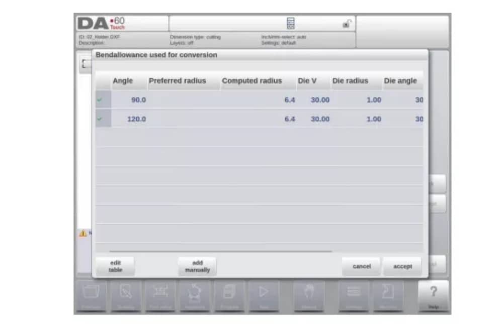
(4) Converting cutting dimensions, with bend allowance info
En la última etapa de conversión de un DXF con dimensiones de corte, el margen de curvatura que se utilizó durante el plegado debe reutilizarse en la conversión.
Therefore the conversion of cutting dimensions will always use the bend allowance table of the control and it will check if for all bends bend allowance information is available.
In case there is just one set of bend allowance parameters available for each bend, this will be used. The bend allowance pop-up will show the angles from the product with the found bend allowance. If more entries in the table can be valid, one needs to select the appropriate bend allowance line. The prefered and calculated radius can be helpful in this selection.
Agregar información de tolerancia de curvatura manualmente
In case the bend allowance information is given with the DXF cutting dimension drawing, included in the DXF or as separate info, there is the possibility to manually enter this information.
When a DXF is imported and the bend allowance value per bend is included (based on the bendline info) these values are imported and used with the desired bend. The control will use this as an input which overules the bend allowance calculation or table search of the control.
If this information is entered during the DXF conversion, this will work equivalently, bypassing the controls calculation or table search.
If the desired bend allowance information is not present from the table, one can also manually add the information just before actual converting. In case the bend allowance is not given before or during the DXF conversion this will be automatically prompted. One can select either to select from excisting entries from the bend allowance table, or enter bend allowance just for this conversion.
To enable the function of programming bend allowance information in the Drawing function of the control (bend property) this needs to be switched on in the product properties. This is automatically done in case of importing.
(5) DXF Settings
En la configuración del convertidor DXF se pueden configurar los parámetros de conversión. Es posible almacenar varios archivos de configuración para tipos de dibujo específicos. Dispone de las funciones "Guardar como" y "Cargar".
Conversion parameters

3. The 3D import function (Profile-T3D offline only)
An alternative for drawing the desired product in the application is to import an externally generated CAD-system file. With the 3D import function Profile-T3D can import the generic .IGES and .STEP files.
This chapter will explain the use of the 3D import functionality for.IGES and .STEP files.
(This functionality is solely available in Profile-T3D)
The 3D import function is started via the Import command button above New Product. Import 3D opens a file selection browser to select an .IGES or .STEP file.
(1) Conversion

The conversion can be started by tapping Convert. This will start the interpretation of the 3D design into a product with bendlines and sheetmetal specific characteristics.
The application will show the product with the designated bendlines.

In case the converter does not find any imperfections the conversion is previewed and one can finalize the conversion with tapping Accept.
From here the product is converted and shown in Drawing mode.
One can continue with tool selection and bend sequence programming.

The 3D CAD file requirements
For the .IGES and .STEP files to be imported it is important to meet the constraints for sheet metal product designs. The constraints are available upon request at Delem.
The 3D file to be imported must of course be generated with the objective to design a sheet metal part which can be processed on a press brake.
4. The DXF contour export option
Como parte de la opción DXF, la función Exportar DXF, en el modo Editar en Productos y en Transferir (Perfil-T), permite exportar cualquier producto, incluyendo las deducciones de plegado, como un contorno. Este contorno se almacena como DXF y contiene las dimensiones de corte.

Dibujo del producto
Para iniciar un nuevo dibujo de producto, seleccione Nuevo producto en la biblioteca de productos.
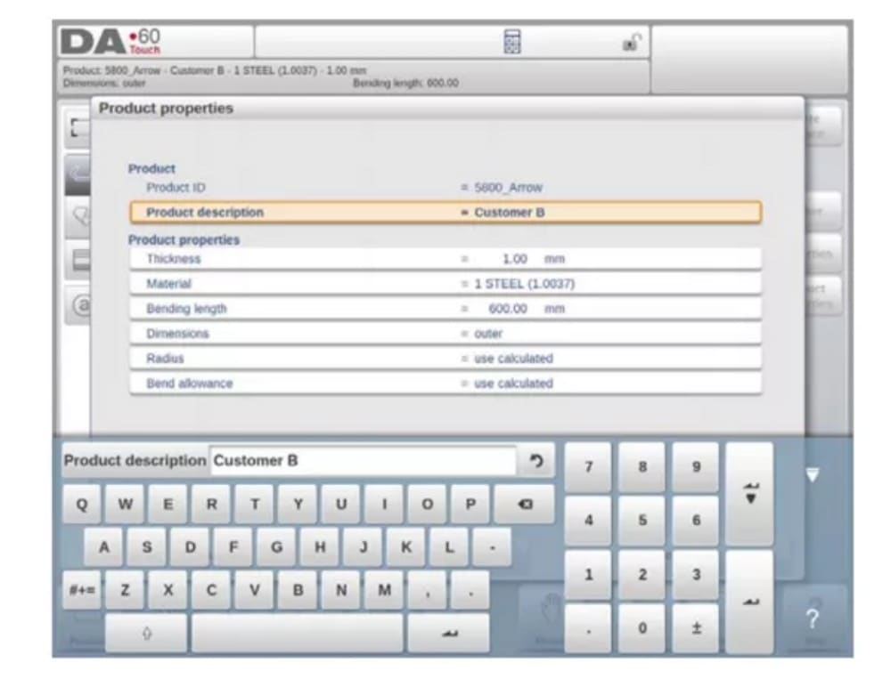
When a new product drawing is started a screen with general product properties appears.
First these properties, general data, should be set before starting with the product drawing.
(1) Add Notes
Al pulsar "Editar notas", aparece una nueva ventana donde puede editar el texto del producto actual. Los caracteres disponibles se muestran en el teclado.

2. 2D product drawing
(1) Introduction
Después de ingresar los datos generales del producto, aparece la pantalla de dibujo.
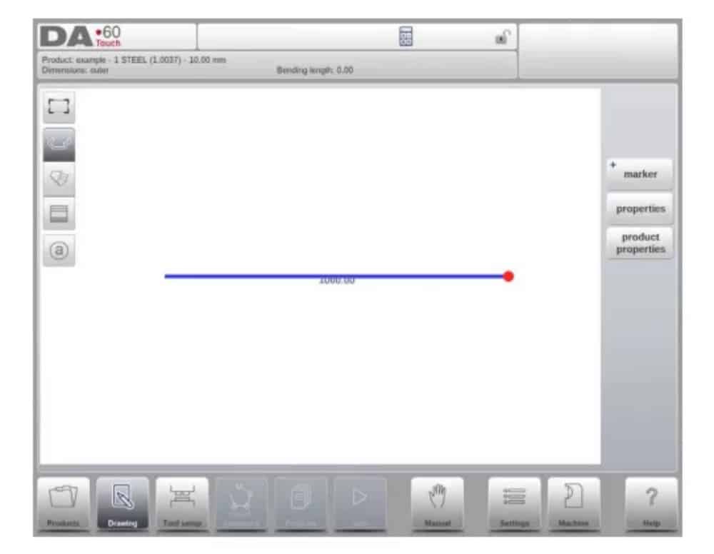
En la fila de información superior encontrará información sobre el ID del producto, la descripción del producto, la selección de dimensiones interiores/exteriores y el directorio real del producto.
Now you can create the profile of the product. It is possible by using your fingers to tap and create quickly the product in ‘sketch’ mode. After that the real product dimensions and corresponding values can be entered by using the keyboard.
También es posible introducir directamente el ángulo de la curva, seguido de la longitud de ese lado, mediante el teclado y la tecla Intro. Las propiedades se muestran en la barra de entrada de la pantalla, en el panel del teclado. Este procedimiento continúa hasta que el producto tenga el perfil deseado.
Los datos del producto se pueden modificar seleccionando Propiedades del producto. Las propiedades de los ángulos y líneas del producto se pueden modificar seleccionando Propiedades.
Configuración de herramientas
1. Introduction
2. Standard procedure
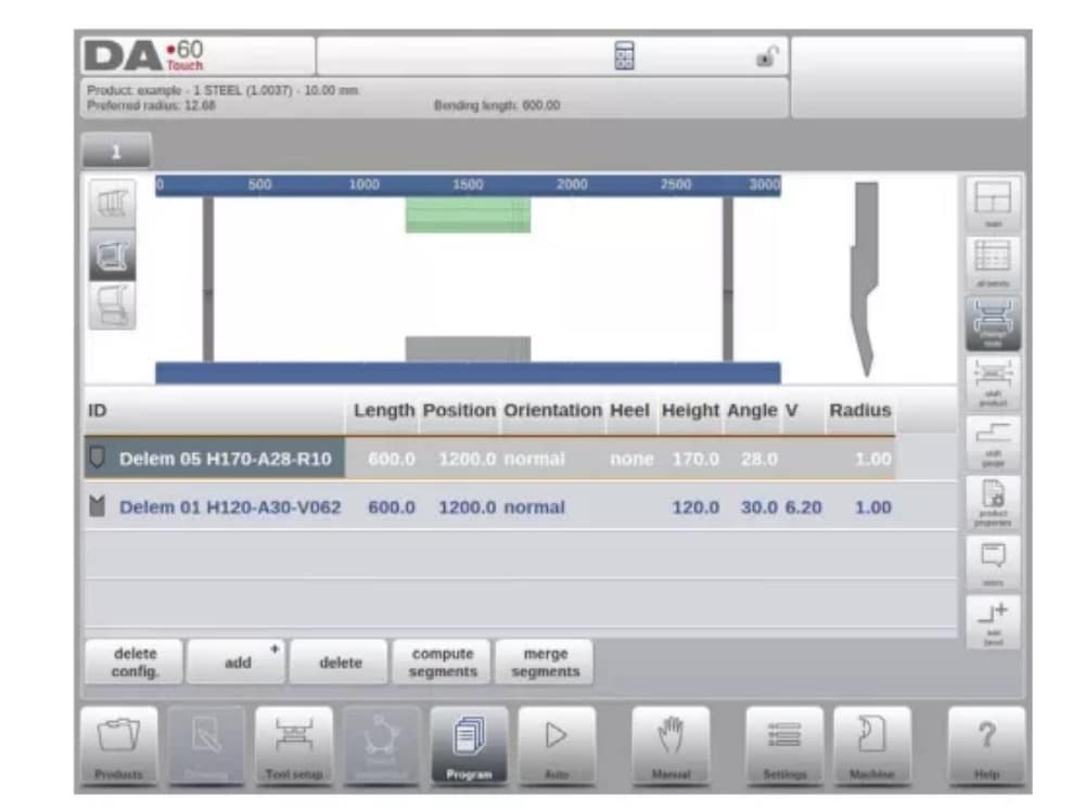
Al activar la función "Configuración de herramientas", la pantalla muestra una vista frontal de la configuración de la máquina en la mitad superior. En la mitad inferior, se muestran los datos de la herramienta. En esta pantalla, se puede programar la ubicación de las herramientas en la máquina.

3. Tool selection
When starting a new tool configuration, the machine opening is empty

Select Add to add a tool to the configuration; punch, die or adapter (if enabled)

Cuando se ha elegido una herramienta (por ejemplo un punzón), se coloca en la máquina con la máxima longitud disponible.

Después de colocar una herramienta, se puede cambiar su ID seleccionando la ID del punzón en la pantalla y tocando la vista de Lista.
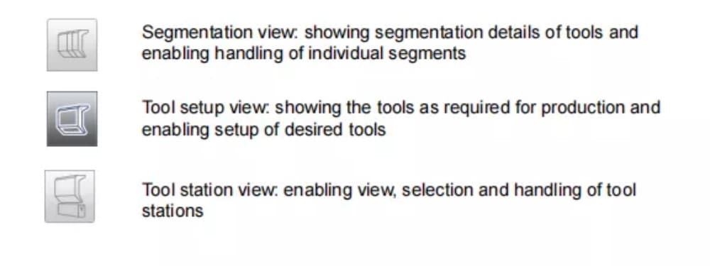
4. Tool segmentation
Al utilizar herramientas segmentadas, a partir de las cuales se pueden componer herramientas del tamaño deseado, el control puede respaldar esto y ayudar a generar la segmentación adecuada.

In below paragraph the functionality for segmentation is explained, including the use of the three views on the tool setup. Next to the Tool Setup screen the ability to have segmentation features available is depending on the programmed segments for each tool. This
programming can be done in Machine mode under the Punches and Bottom dies libraries.
More on programming of segments in the Tool library can be found at the end of this paragraph.
En la pantalla Configuración de herramientas, hay tres modos de visualización disponibles. Con los botones de selección a la izquierda de la vista frontal de la máquina, se pueden elegir las siguientes vistas:
5. Segmentation of individual tools
After the proces of setting up the desired tools for the products to be made, the Bend
Sequence mode can calculate the most efficient bend sequence.
Upon desire the tools can be segmented, helping in the selection of the segments creating the correct tool length.
The tool segmentation function automatically calculates the required segmentation and uses the assignments “maximum inter tool distance” and upon choice the “tool length tolerance” for finding the best solution

6. Station selection and repositioning
La tercera vista de Configuración de Herramientas es la vista de Estación. En esta vista, las estaciones de herramientas completas se resaltan al seleccionarlas y se pueden reposicionar programando una posición alternativa o arrastrándolas a la nueva posición deseada en la máquina.
A toolstation is automatically defined when there is an overlap from punches with dies. This, meaning that a toolstation is considered a station when e.g. there is an exact position of punch and die opposite of each other. When there is a shifted position but still overlap in
between punch and die, this is still considered a tool station. Even when two punches are opposite of a single die, which can be useful bending constrained bends, this is considered a toolstation. These stations can be repositioned without losing their relative positioning.

La vista de la estación no cambia nada en los detalles de la herramienta.
Secuencia de curvatura
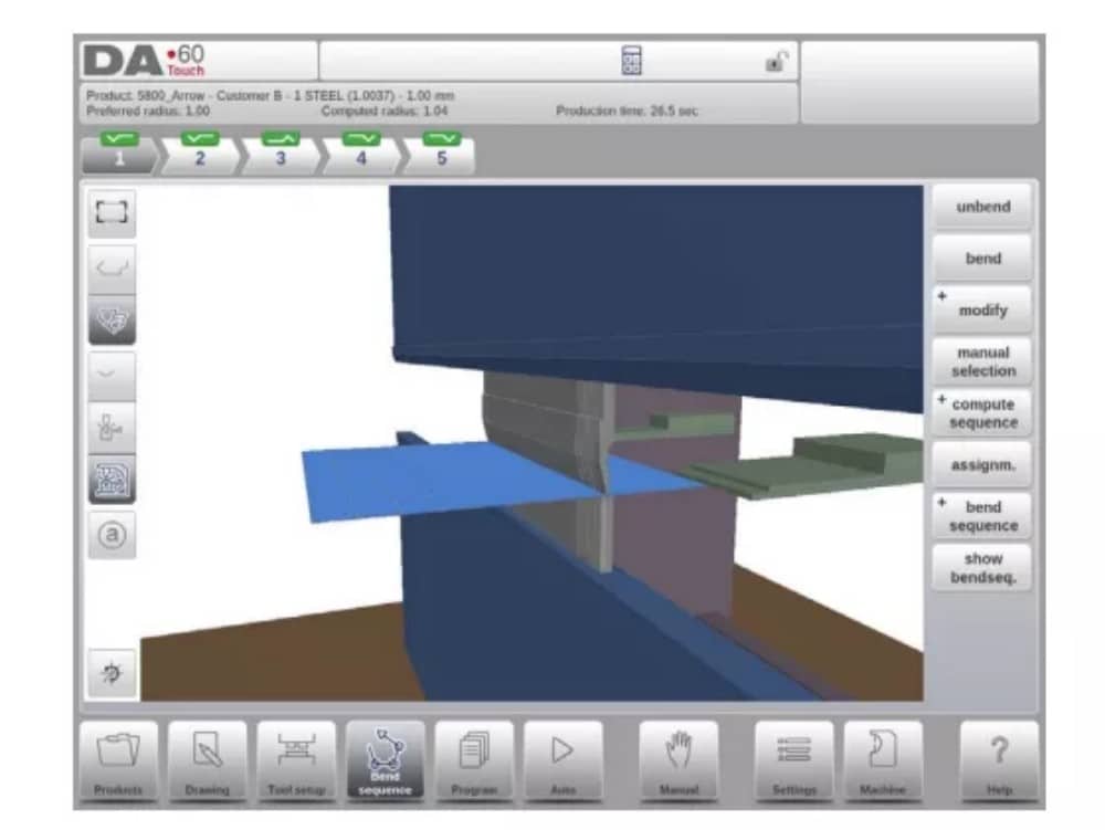
1. Introduction

Cuando hay una configuración de herramienta disponible, se puede iniciar la simulación de plegado para determinar la secuencia de plegado del producto activo. La determinación de la secuencia de plegado se inicia pulsando el botón de navegación "Secuencia de plegado".

The bendsequence determination can be realised by automatic calculation starting with the bent product. It is also possible determining the sequence manually starting with the flat
product, not using the automatic calculation.
En la pantalla de secuencia de plegado, el producto aparece entre las herramientas en una posible posición de último plegado. Al iniciar la simulación, el producto se muestra en su estado final. Para obtener una secuencia de plegado, el producto debe desplegarse desde el último plegado hasta el primero. Esto se puede hacer con las teclas de función disponibles.
Cuando se prefiere comenzar con un producto desplegado para elegir manualmente la secuencia de doblado, esto se puede elegir bajo el botón de comando Secuencia de doblado.
(1) View select
Within the bendsequence screen views can be switched upon required choice.
The view functions are located oposite of the command buttons in the main screen.
Ver funciones

(2) Bend selector
En la pantalla de secuencia de curvas, se pueden seleccionar y navegar las curvas con el selector de curvas. En la parte superior de la pantalla se indica el número de curvas con selectores de curvas preliminares. Tras completar la secuencia de curvas, todas estas se colorean, se activan y muestran un indicador de giro.

Desde allí, se pueden tocar fácilmente las curvas para seleccionar los datos deseados. En el selector de curvas, el indicador de giro se mostrará en verde, amarillo o rojo para indicar el nivel de cumplimiento de las asignaciones de la secuencia de curvas.

2. Unbend product
Para generar un programa CNC, es necesario conocer la secuencia de plegado. Hay dos maneras de lograrlo:
• Pulse la tecla de función Calcular. El control calculará automáticamente la velocidad más rápida.
Posible secuencia de curvatura para este producto.
• Pulse la tecla de función Desenrollar repetidamente hasta que el producto quede completamente desenrollado.
Cuando el producto esté completamente desdoblado, presione la función Secuencia de doblado y Guardar para generar y guardar el programa CNC.

3. Manual selection of bends
Normally the control proposes the next (un)bend in a sequence. This is computed by the control depending on the programmed assignments and of course the product shape and applied tools. For various reasons it can be necessary to choose another bend for the bend sequence. The bend sequence can be changed/determined through the function Manual
Selection. When the function Manual Selection has been choosen, a new window is opened.

4. Assignments
(1) Introduction
The Assignments are parameters with which the bend sequence computation is controlled.
The assignments screen is opened from the tool configuration screen with the function key
Assignm.
El cálculo automático de la secuencia de plegado funciona con varias condiciones para encontrar el punto óptimo entre un tiempo de producción mínimo y posibilidades de manipulación sin colisión producto/máquina y producto/herramienta.
Para encontrar uno de los valores óptimos, se deben programar varios parámetros de cálculo con los que se pueda calcular la secuencia de plegado. Algunos de estos parámetros están relacionados con la máquina y otros con la precisión del producto, las posibilidades de manipulación y los tiempos de giro.
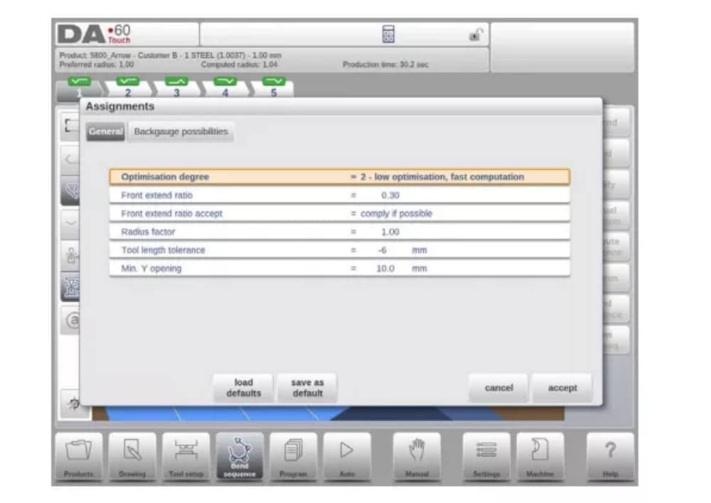
(2) Assignments – general
Grado de optimización
Rango 1-5.
Aquí se debe introducir el número de alternativas que se deben calcular para cada curva.
Cuanto mayor sea este número, más alternativas deberá examinar el control, por lo que mayor será el tiempo de cálculo:
1 – optimización más baja, cálculo más rápido
2 – baja optimización, computación rápida
3 – optimización media, computación media
4 – alta optimización, computación lenta
5 – máxima optimización, computación más lenta
(3) Assignments – Backgauge possibilities

5. Show bend sequence
Cuando se pulsa la función Mostrar secuencia de curvatura, se muestra una descripción gráfica de la secuencia de curvatura.

Esta opción se puede activar en cualquier momento tras el primer desdoblamiento. La vista gráfica muestra tanto los pliegues determinados como los pendientes (signo de interrogación).
Cada imagen de la vista general se puede ampliar o reducir individualmente con las funciones disponibles. También se pueden girar con el dedo.
Programación de productos
1. Introducción

Para editar un programa CNC existente, seleccione un producto en la vista general de Productos y seleccione el botón de navegación Programa. Al iniciar un nuevo programa, seleccione Nuevo Programa y, tras introducir las propiedades principales del producto y la configuración de herramientas, el sistema cambiará automáticamente a Programa.
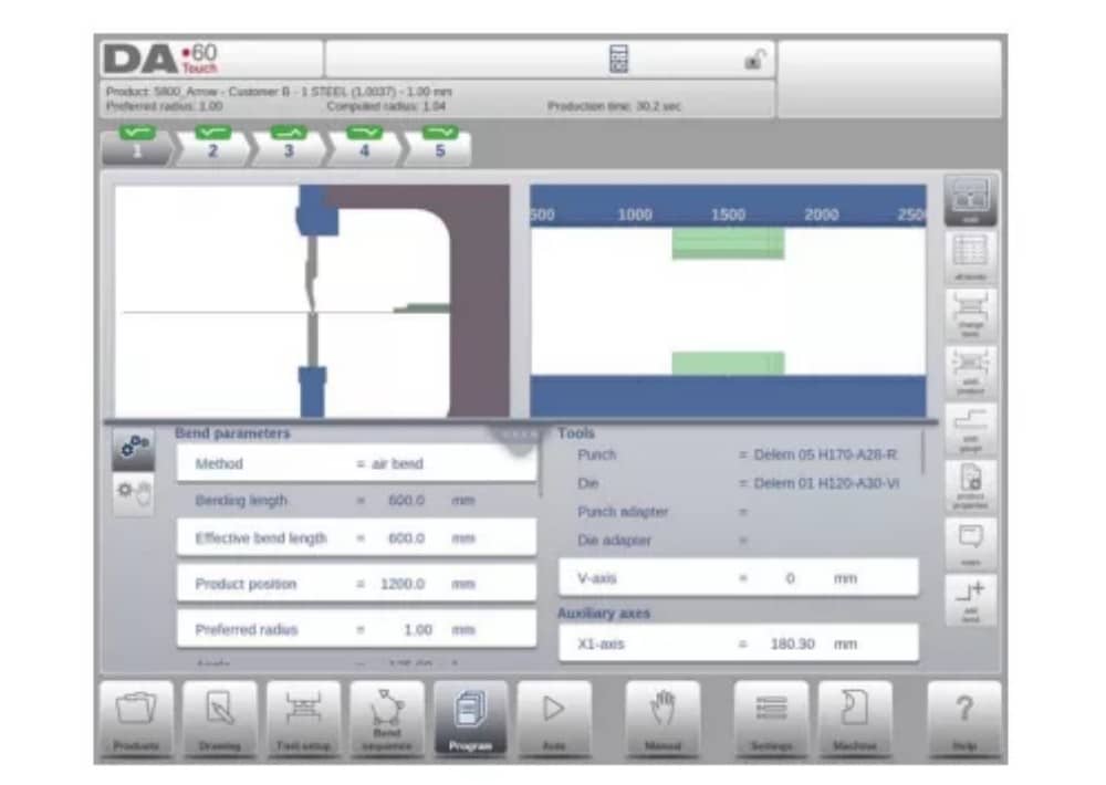
En ambos casos, debería aparecer una pantalla como la mostrada arriba. La programación y la modificación de datos se realizan de la misma manera en ambos casos.
La pantalla principal muestra el programa numérico existente o, al iniciar un nuevo programa, el primer pliegue programado. El selector de pliegues, en la parte superior de la pantalla, permite navegar por los pliegues. Se pueden tocar los pliegues indicados para seleccionar fácilmente los datos deseados.
Al lateral de la pantalla principal se indican las vistas y funciones con botones de comando.
Funciones
Están disponibles los siguientes modos/funciones:

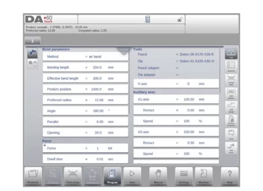
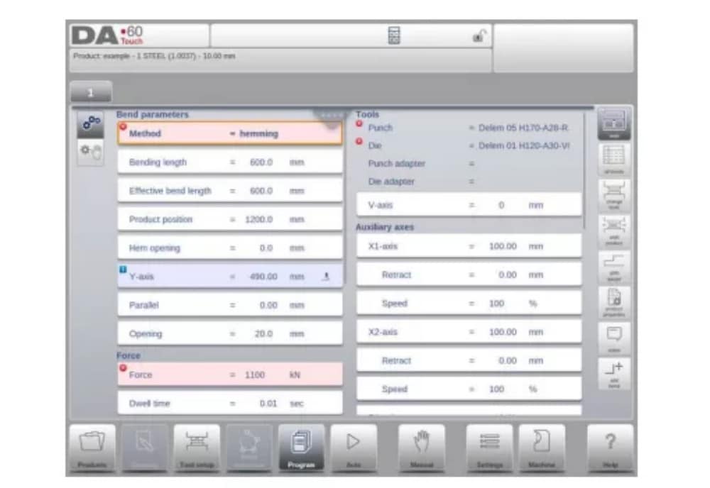
2. Program mode, parameter explanation
La pantalla principal muestra las curvas disponibles y desde esta pantalla principal, de cada curva disponible, se pueden ver y editar parámetros específicos.
El ID y la descripción del producto se muestran en la fila superior de la pantalla.
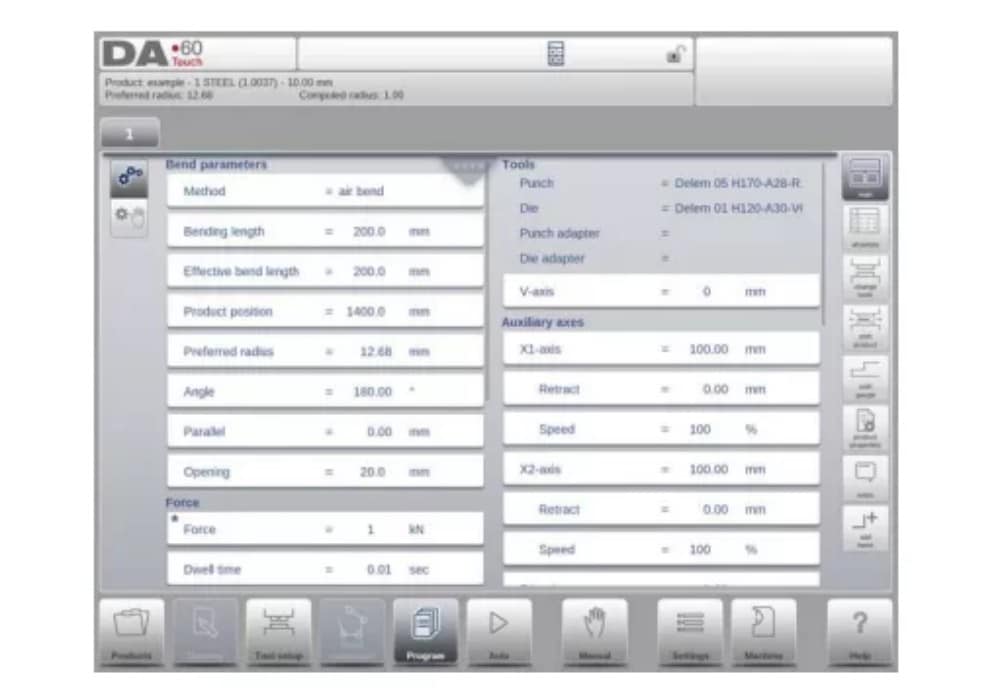
En el caso de un producto gráfico, también se puede mostrar información gráfica.
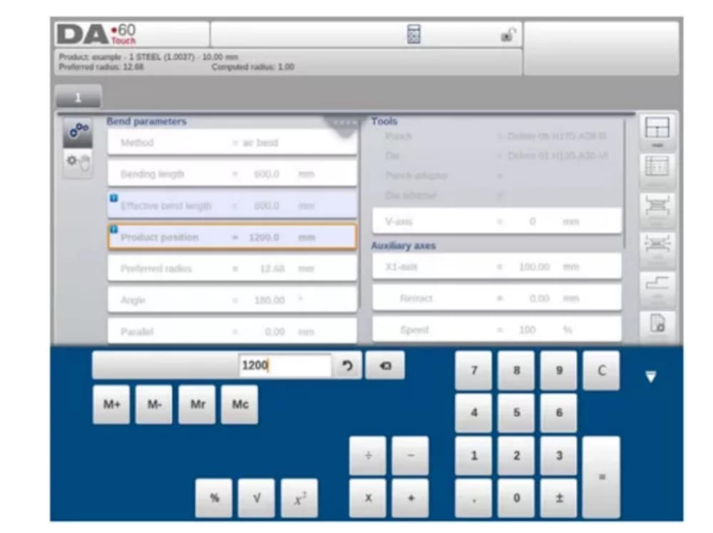
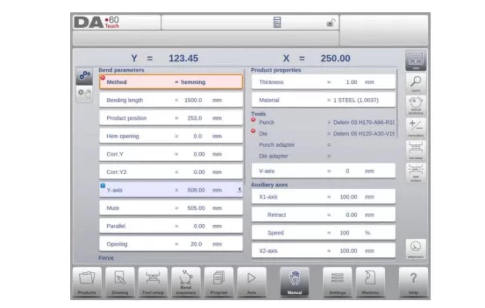
(1) Bend parameters
Métodos de curvatura

(2) Force
Fuerza
Fuerza máxima ajustada durante el prensado (calculada automáticamente).
Tiempo de permanencia
Tiempo de retención del punzón en el punto de doblado.
Velocidad
Velocidad
Velocidad de trabajo (velocidad de prensado). Inicialmente, el valor de este parámetro se copia del parámetro "Velocidad de prensado predeterminada" en el modo Configuración.
Funciones
Repetición
0 = bending is skipped
1 a 99 = el número de veces que se repetirá esta flexión.
3. Edit / view modes
(1)All Bends
Cuando se pulsa la función Todas las curvas, aparece una vista general completa de las curvas.

From within this screen, the complete CNC program can be edited. All bend parameters can be edited within the table and bends can be swapped, moved, added and deleted.
The available columns can be scrolled by finger movement / swipe.
(2) Change tools
Para cambiar las herramientas, se puede usar el menú "Configuración de Herramientas". Al usar el modo Programa para programación numérica, se usará la configuración de herramientas como estándar. Si es necesario cambiar la configuración de herramientas para un solo paso de plegado, se puede usar el botón "Cambiar Herramientas". El control siempre preguntará si los cambios deben aplicarse a toda la configuración o solo a un plegado. Si se requiere la configuración completa de la herramienta, se cambiará automáticamente al menú "Configuración de Herramientas".
4. Programming parameters
Parameters in program mode can be programmed one by one. The effect of the parameter on other parameters can be computed either automatically or manually. This depends on the selected mode on the left-hand side of the screen. The Auto Computation switch enable to select between:
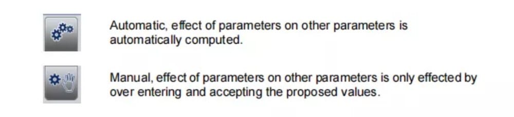
La relación entre los parámetros se visualiza con un símbolo y un color de fondo.
Modo automático
1. Introducción
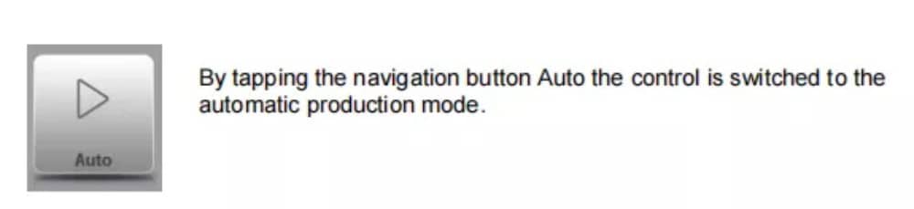
En el modo automático con el programa activo, se puede iniciar la producción. Tras entrar en modo automático, se puede pulsar el botón de inicio para iniciar la producción.
The automatic mode executes the program automatically bend by bend after pushing the Start button. When selecting a different product in Products mode, which is in the library and has already been used for production, one can immediately switch to Auto and start production.
Every time after a different bending program is selected you must check your tools and tool positions in your machine. This is also indicated with a ‘check tools’ warning message when you enter the automatic mode.
2. View modes
The auto mode screen is offering a diversity of views which, depending on ones production methode, can be chosen. When selecting auto mode for the first time, the main screen will appear. On the right side of the screen the available view modes can be selected.
Están disponibles los siguientes modos de visualización:
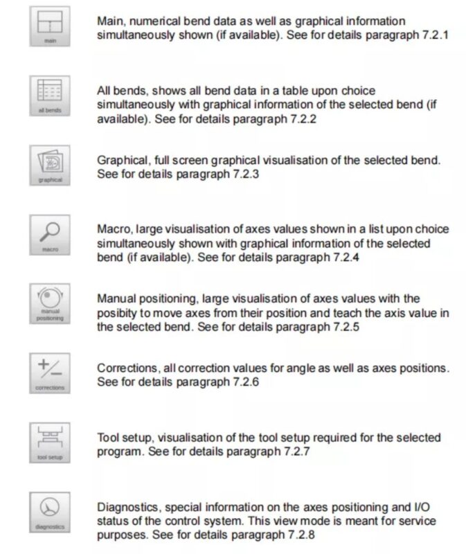
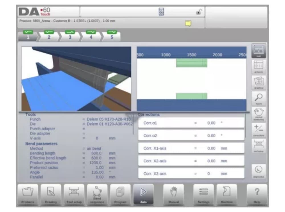
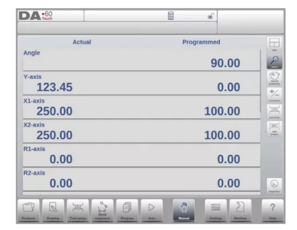
(1) Main
Main view shows the numerical data of the bend along with the corrections. The corrections can be programmed here. The splitter control devides the screen in graphical visualisation and the numerical data. This can be closed if only numerical data is required.
(2) All bends
The all bends view mode shows, with or without the opened graphical pane, a table including all bend data. The bends are shown row wize and the columns display all bend parameters.

(3) Graphical
En el modo de vista gráfica, se ofrece una vista gráfica en pantalla completa del proceso de doblado.

(4) Macro
Con el modo de vista macro, el control cambia a una vista que muestra solo los valores de los ejes grandes en pantalla. Esta vista se puede usar cuando se trabaja a cierta distancia del control, permitiendo leer los valores de los ejes.

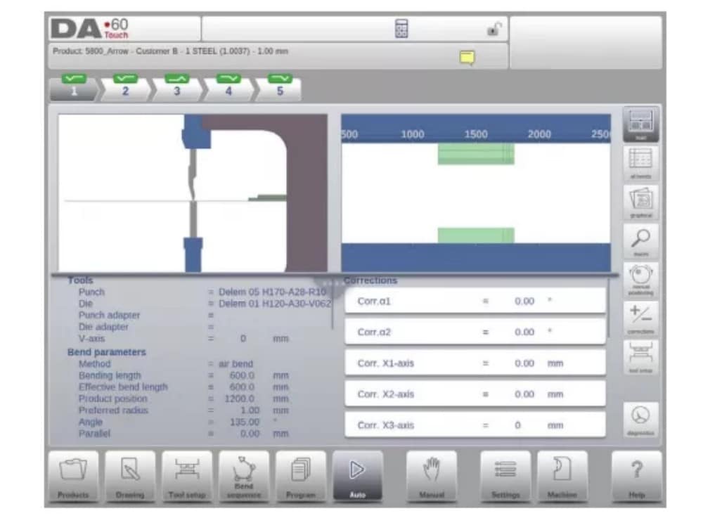
(5) Manual positioning
In manual positioning view mode the axes values are shown at large. Axes can be selected and while selected the position can be controlled by turning the handwheel.
El indicador de enseñanza:

When the teach indicator arrow is pressed, standing in between actual value and programmed value, the value is tought to the program step
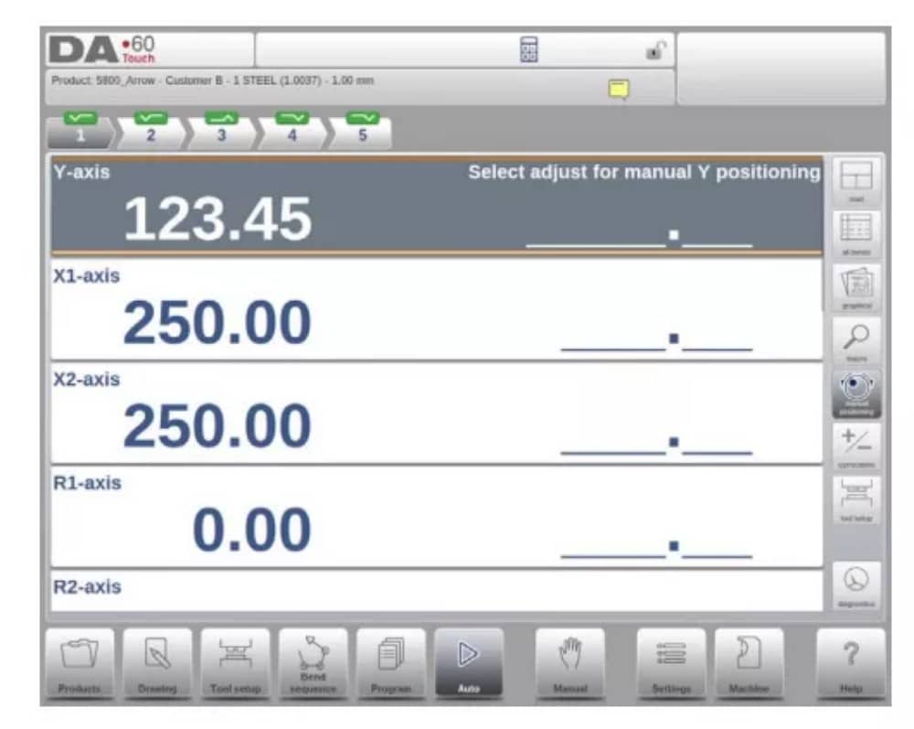
3. Notes
The notes which can be added to a product or program can be viewed in Automatic mode.
With the presence of the notes indicator its indicated that notes are added to this product and by tapping the indicator these will be shown.
Se pueden añadir notas a un producto o programa, pero también a curvas específicas. También se pueden incluir documentos PDF en las notas. El botón PDF abrirá el documento.
4. Bumping correction
In case of a selected bumping bend a general correction for a bumping bend can be entered. This function is only available if a product is loaded that contains a bumping bend.
Con Bumping Corr. aparece una nueva ventana en la que se puede introducir la corrección.

Modo manual
1. Introducción
En el modo manual, se programan los parámetros para un plegado. Este modo es útil para pruebas, calibración y plegados individuales.
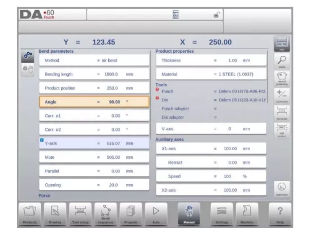
El modo manual es independiente del modo automático y se puede programar independientemente de los programas en la memoria.
2. Programming parameters & Views
Los parámetros en modo manual se pueden programar uno por uno. El efecto de un parámetro sobre otros parámetros se puede calcular de forma automática o manual. Esto depende del modo seleccionado en el lado izquierdo de la pantalla. El interruptor de Cálculo Automático habilita...
seleccione entre:
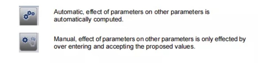
La relación entre los parámetros se visualiza con un símbolo y un color de fondo.
3.Macro
Con Macro, el control cambia a una nueva vista con solo valores de ejes grandes en pantalla. Esta vista se puede usar cuando se trabaja a cierta distancia del control, permitiendo leer los valores de los ejes.
4. Manual movement of the axes
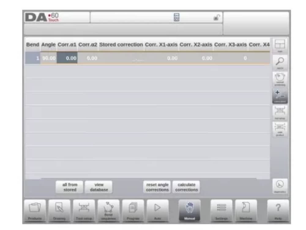
5. Corrections
En este modo de visualización se muestran las correcciones para el pliegue programado en modo manual. Dado que siempre se trata de un pliegue único, se mostrará una sola línea.
6. Diagnostics
Al pulsar Diagnóstico, el control cambia a una vista que muestra el estado de los ejes. En esta ventana, se puede observar el estado actual de los ejes disponibles. Esta pantalla también puede estar activa mientras el control está en marcha. Por lo tanto, permite supervisar el comportamiento del control durante un ciclo de plegado.

Ajustes
1. Introducción

The Settings mode of the control, which can be found in the navigation panel, gives access to all kind of settings which influence the programming of new products and programs.
Default values and specific constraints can be set.
La configuración se divide en varias pestañas que organizan lógicamente los diferentes temas. En las siguientes secciones se describen las pestañas disponibles y la configuración detallada.

2. General
Seleccione la pestaña deseada y toque el parámetro que desea modificar. Si los parámetros tienen un valor numérico o alfanumérico, aparecerá el teclado para introducir el valor deseado. Si la configuración o el parámetro se pueden seleccionar de una lista, esta aparecerá y podrá seleccionarse.
Se realiza tocando. Las listas más largas permiten desplazarse verticalmente para consultar los elementos disponibles.
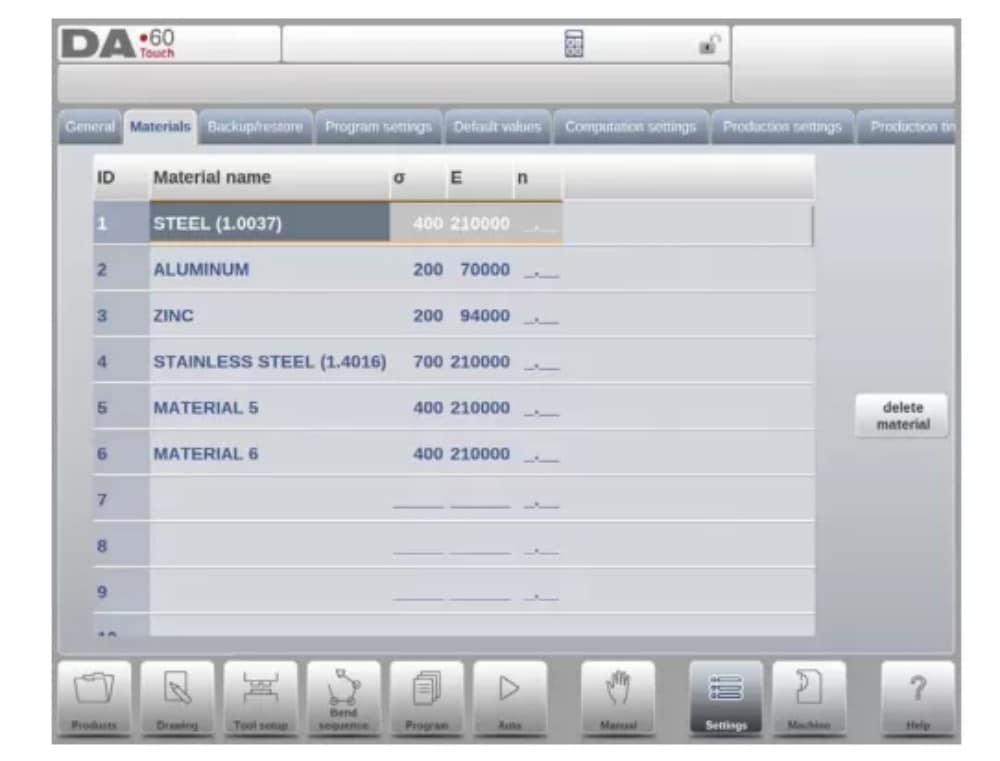
3. Materials
En esta pestaña se pueden programar materiales y sus propiedades. Se pueden editar, añadir o eliminar materiales existentes. Se puede programar un máximo de 99 materiales en el control.
4. Backup / restore
Esta pestaña permite realizar copias de seguridad y restaurar productos, herramientas, configuraciones y tablas. Si los productos o herramientas provienen de modelos de control anteriores, también se pueden restaurar con formato de archivo DLC mediante esta función de restauración específica.
Para los materiales, una copia de seguridad y restauración específicas están disponibles aquí.
Se pueden realizar copias de seguridad y restaurar herramientas y productos según los siguientes procedimientos. Los procedimientos para guardar o leer datos son similares para todos los tipos de medios de copia de seguridad, por ejemplo, red o memoria USB.

The actual backup directory consists of a device (USB stick, network) and a directory. The choice of devices depends on which devices have been connected to the control. If necessary, directories can be created and selected. The backup locations for storage of products and tools can be set independently.
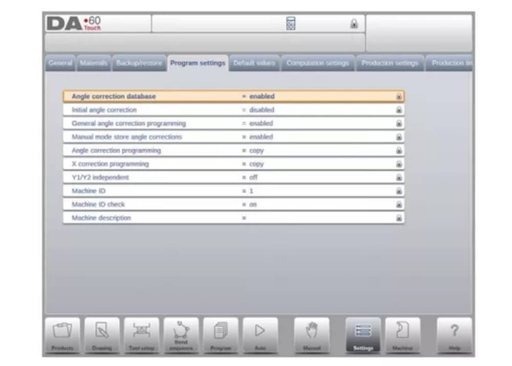
5. Program settings
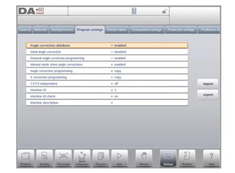
Base de datos de corrección de ángulos
Parámetro para habilitar la base de datos con correcciones de ángulos.
6. Default values
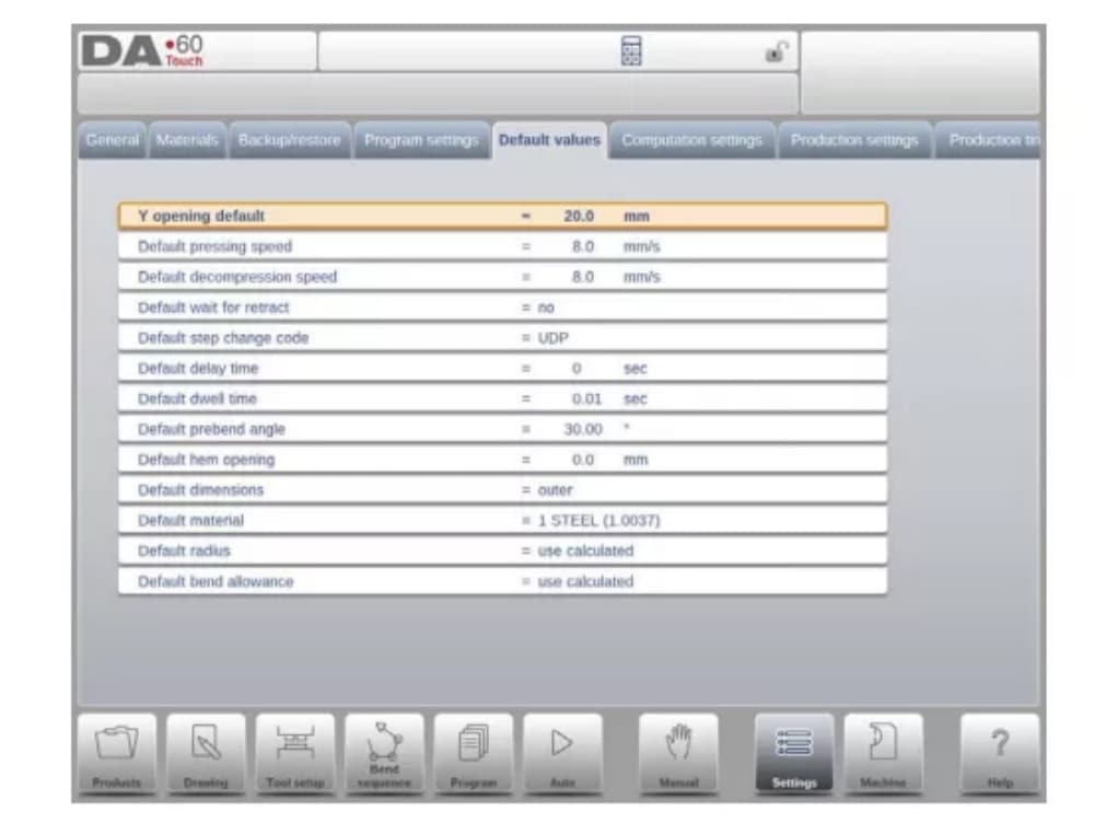
Y opening default
Default Y-axis opening, used as initial value for the parameter ‘opening’ in a new program.
7. Computation settings
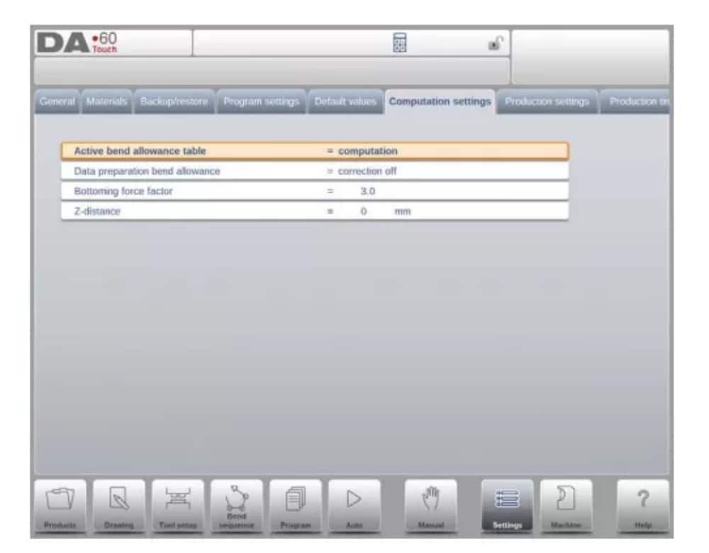
Tabla de tolerancia de curvatura activa
computation => the control will calculate the bend alowancetable => the bend allowance table will be used
Bend-allowance is the correction of the X-axis due to sheet shortening after bending.
With this parameter the method for bend-allowance calculation is chosen. ‘Computation’ means the standard formula of the control is used to calculate the bend-allowance.
‘Table’ means a bend-allowance table with correction values can be used.
8. Production settings
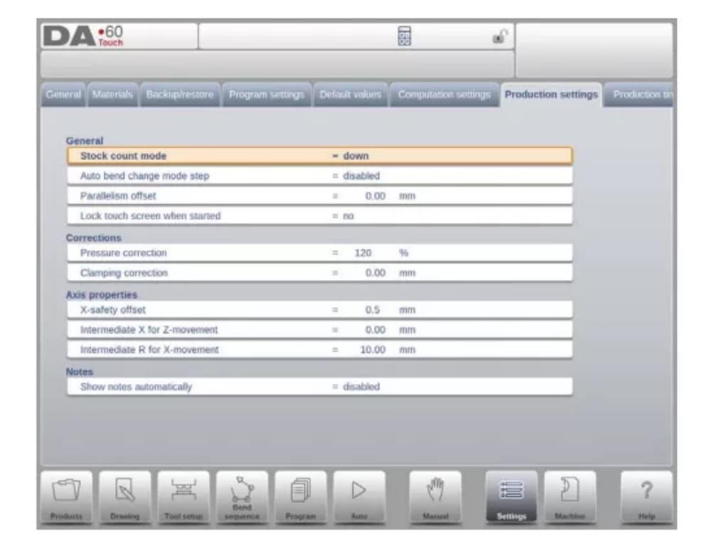
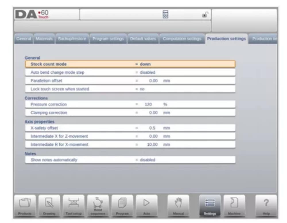
Modo de conteo de existencias
Configuración para el contador de stock en modo de producción, para que el contador de stock (contador de producto) cuente hacia arriba o hacia abajo.
When down counting is selected, the stock counter in production mode is decremented after each product cycle. When the counter has reached zero, the control is stopped. On
the next start action, the stock counting value is reset to its original value.
When up counting is selected, the counter is incremented after each product cycle.
El conteo regresivo puede ser útil si se debe producir una cuota planificada previamente. El conteo progresivo puede utilizarse para generar un informe sobre el progreso de la producción.
9. Production time calculation
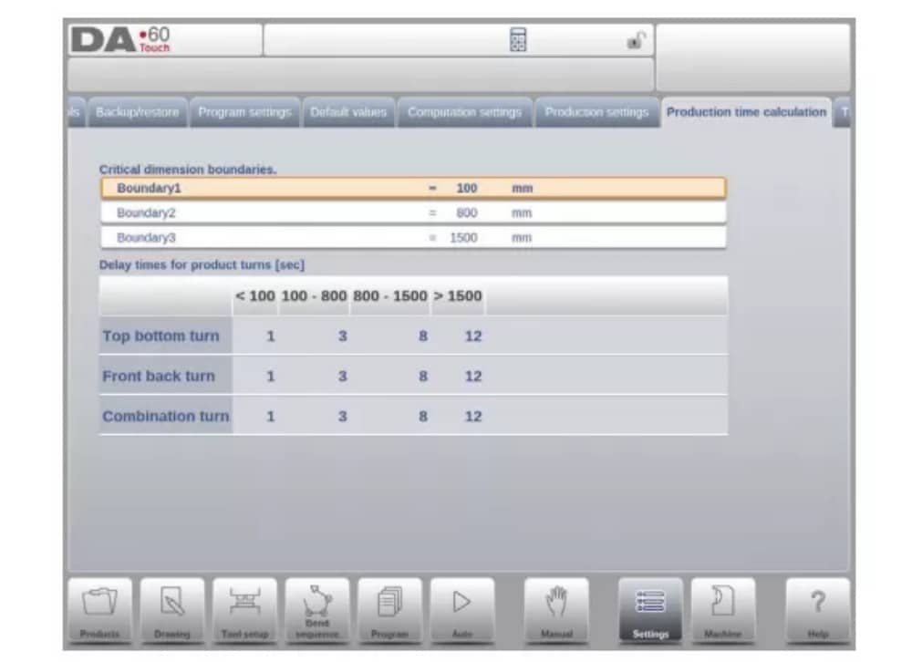
The parameters on this page are used to calculate the production time for a product in the bend sequence computation process. This production time depends on the positioning speed of the axes and the product handling times. The positioning speed is depending on machine settings.
10. Time settings

Tiempo de visualización
Muestra la fecha y la hora en el panel de título, solo la hora o ninguna hora.
Máquina
1. Introducción
The Machine mode of the control, which can be found in the navigation panel, gives access to the configuration items of the machine and specific machine characteristics which influence generic calculations and machine behaviour.
La configuración se divide en varias pestañas que organizan lógicamente los diferentes temas. En las siguientes secciones se describen las pestañas disponibles y la configuración detallada.
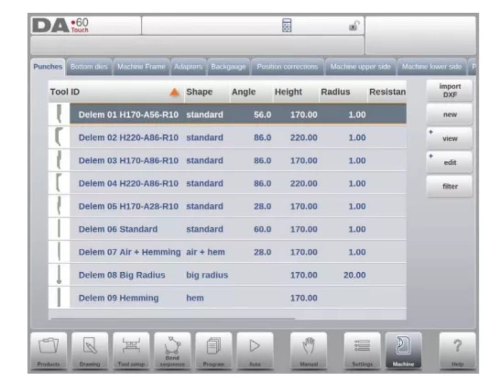
2. Programming of Punches
In this tab, the punches used in the machine can be programmed. New punches can be added; existing punches can be edited, copied, renamed and deleted.
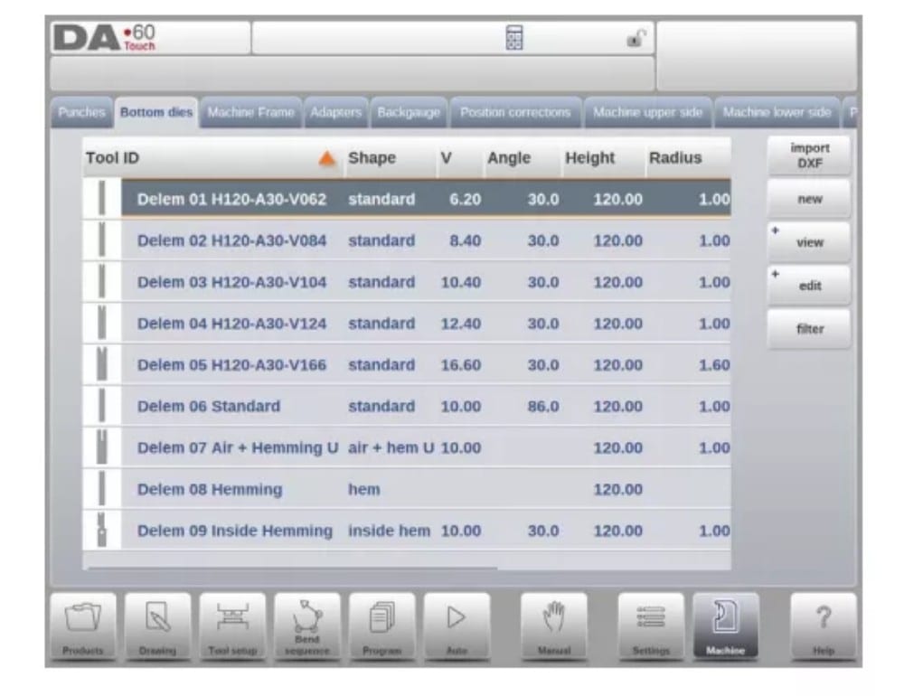
3. Programming of bottom dies
En esta pestaña, se pueden programar los troqueles inferiores utilizados en la máquina. Se pueden añadir nuevos troqueles, y los existentes se pueden editar, copiar, renombrar y eliminar.
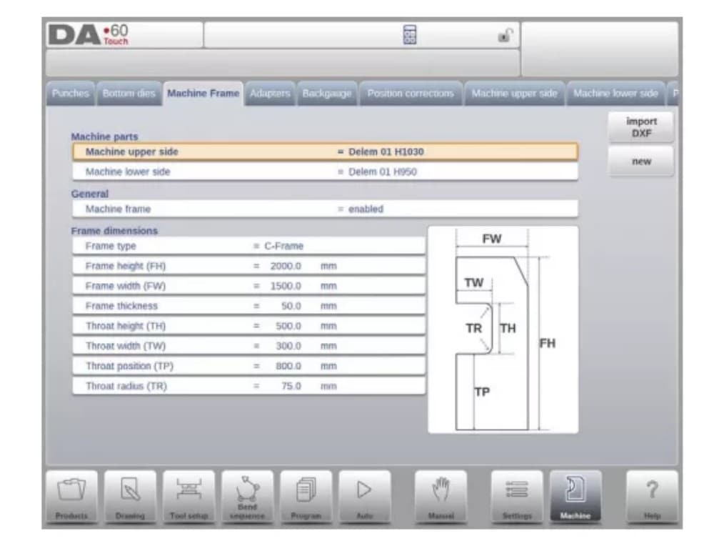
4. Machine frame
En esta pestaña se pueden seleccionar y configurar las geometrías activas de la máquina, desde la viga superior e inferior hasta los marcos laterales. También se puede programar la identificación de la máquina.
Además de la Parte Superior de la Máquina y la Parte Inferior de la Máquina que se eligen entre las disponibles, en esta página se pueden programar las dimensiones del marco lateral.
La forma de la máquina se muestra en la pantalla de simulación durante la programación gráfica y se utiliza para la detección de colisiones de la pieza de trabajo contra la máquina.
5. Adapters
En esta página se pueden habilitar y programar los adaptadores de herramientas.
Upon choice upper adapters as well as lower adapters can be enabled. The default adapter, which will be chosen when an adapter is added to the tool setup, can also be set.
Al añadir un adaptador, primero se deben especificar los parámetros básicos según una plantilla. En la segunda etapa, se pueden dibujar los detalles del adaptador como cualquier otro punzón o matriz.
6. Backgauge
Las dimensiones del dedo del tope trasero tienen en cuenta el movimiento del eje R y el movimiento correspondiente del eje X. Además, se calcula la colisión entre la pieza y el tope trasero utilizando estas dimensiones.
7. Position corrections

8. Machine upper side
En esta pestaña se puede programar la geometría de la máquina para la viga superior, como perfil. Esta información se utiliza para detectar colisiones entre el producto y la máquina.
When e.g. utilities are added to the machine in special cases, these can be programmed as a special machine shape to enable the collision calculations to take this into account.
In most instances there is only one shape programmed.
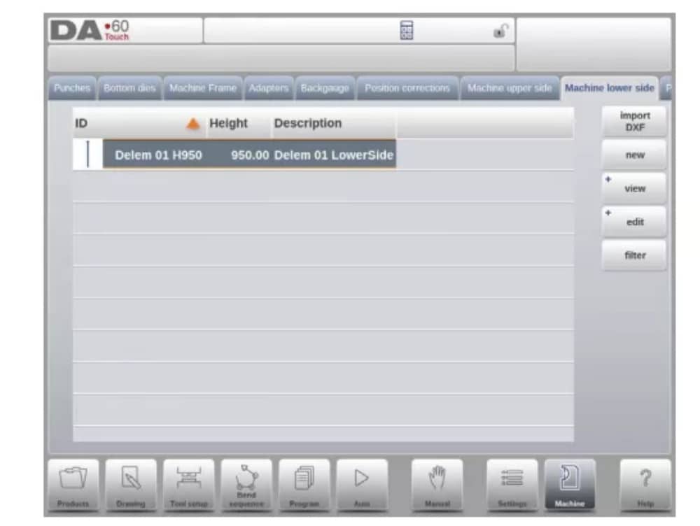
9. Machine lower side
En esta pestaña se puede programar la geometría de la máquina para la parte inferior (mesa), a modo de perfil.
This information is used in the collision detection of collisions with product and machine.
When e.g. utilities are added to the machine in special cases, these can be programmed as a special machine shape to enable the collision calculations to take this into account.
In most instances there is only one shape programmed.
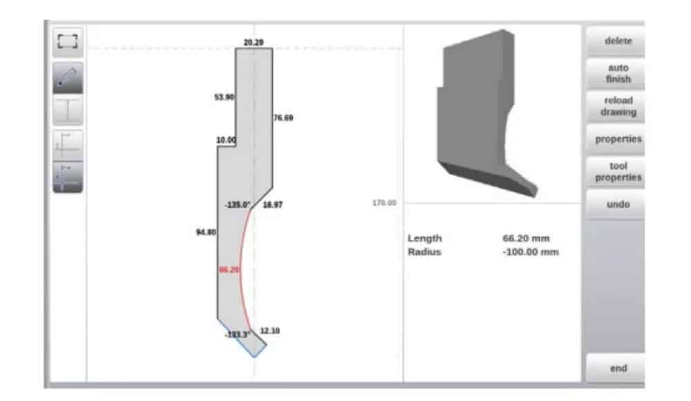
10. Drawing functionality for tools, adapters and machine shapes
In programming punches, dies, adapters and also machine shapes, after the main data the control provides the functionality to freely draw the desired shape in the object. This
functionality makes the objects appear more realistic but most of all enables the control to do an accurate collision prevention.
11. DXF import for tools, adapters and machine parts
Within the tool library, Punches, Bottom dies, Adapters as well as the machine shapes, Machine upper side, Machine lower side and Machine Frame, one can find the optional DXF
import function. This function enables the import of the contour from a DXF file.
Import DXF opens the file browser enabling the selection of the DXF file of the desired shape.

12. Protractor

13. Event logging
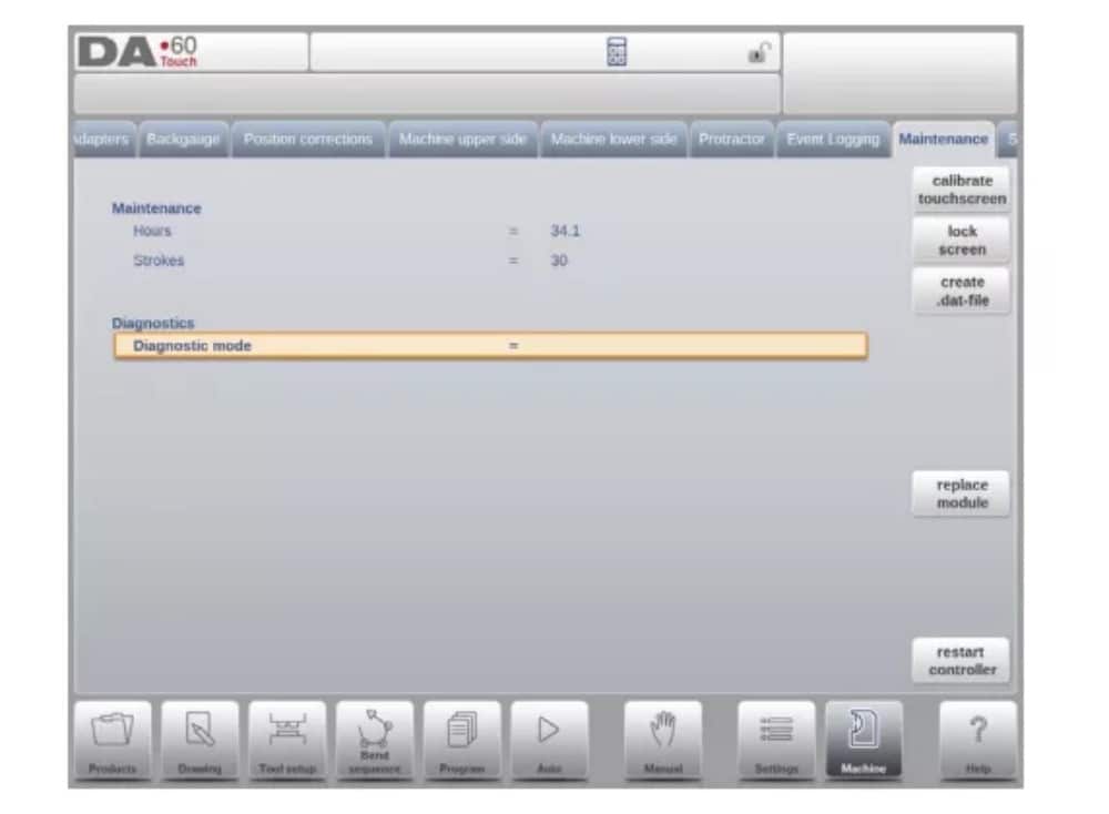
14. Maintenance
En esta pestaña se encuentran las funciones de mantenimiento. Además del contador de horas y el contador de carreras de la máquina, también se encuentran funciones para facilitar el reemplazo de módulos y almacenar datos de diagnóstico.
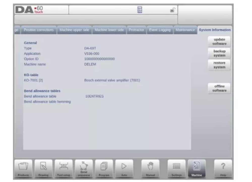
15. System information
En esta pestaña se encuentra la información del sistema. Además de la información de la versión del software, también se pueden leer los ID de los módulos instalados y la versión de los archivos OEM.
Además de la información, aquí también está disponible la funcionalidad de actualización de software.
Perfil-T
1. Introducción
(1) General
El programa sin conexión Profile-T ofrece una interfaz de usuario similar a la del control Delem de la línea DA-Touch. Los capítulos anteriores, que describen el funcionamiento y el uso del control DA-Touch, deben servir de referencia para el uso de este software sin conexión. Este capítulo se centrará en algunas funciones especiales que solo están disponibles en el software Profile-T.
(2) System requirements
To run Profile-T on a computer it should at least be equipped with the following features:
• PC compatible con IBM;
• Minimum Screen resolution of 1024×768
• Windows XP / Windows 7;
• Reproductor de CD-ROM (sólo para sistemas distribuidos de CD-ROM);
• Free USB port
(3) Profile-T distribution & manuals
Depending on the purchase package the Profile-T software is distributed on a CD-ROM or can be generated at the control.
2. Profile-T operation
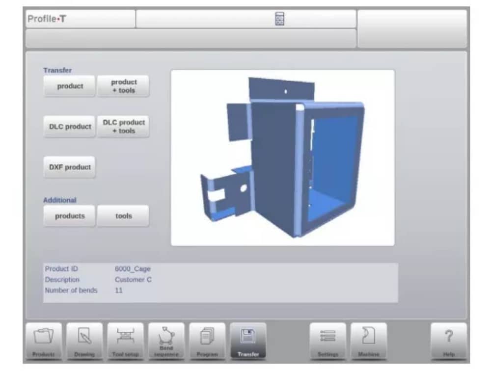
(1) Profile-T principle
The next figure shows the start page of Profile-T:
(2) Machine library
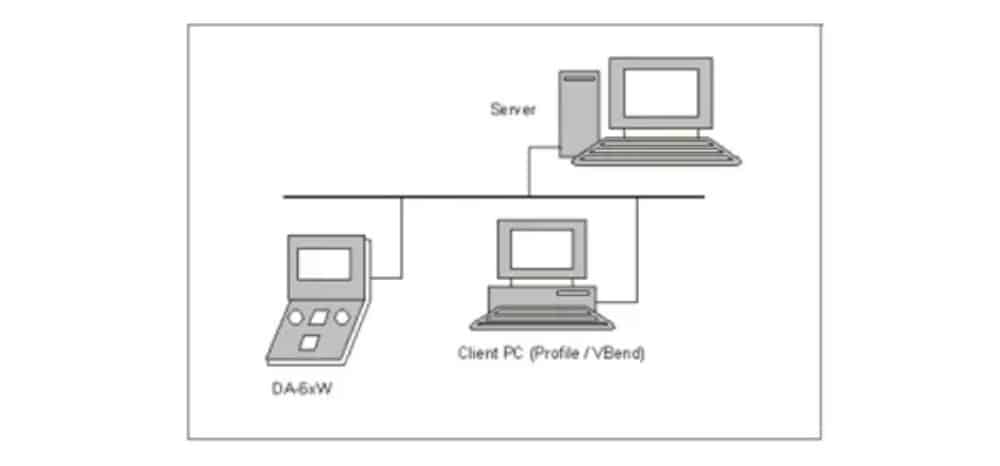
It is important that the parameters in Profile-T are the same as in the control on the machine.
In this way the offline generated programs are 100% compatible with the control system. In Profile-T you install several machines in order to use 1 offline programming station for the complete machine range on the production floor.
(3) Print functionality (Profile-T2D and Profile-T3D only)
In Products mode it is possible to generate a print out of the selected product (Profile-T 2D and Profile-T 3D only). When pressing the button ‘print’ the standard Windows printer menu is opened to select the desired printing device and printer settings
(4) Transfer mode
Una vez finalizado el diseño del producto y la generación del programa CNC, estos datos se pueden transferir en modo de transferencia a, por ejemplo, un dispositivo de memoria USB.