Struggling to master your DELEM DA-69T Dobradeira? This guide will help you understand the operation steps to ensure precise bending and improved productivity.
The DELEM DA-69T Dobradeira provides advanced control features for accurate bending. Learn the step-by-step instructions for its optimal operation and how to avoid common mistakes that hinder productivity.
Now, let’s explore the setup process and key features to optimize your DELEM DA-69T press brake for seamless operations.
Visão geral da operação e introdução geral
1. The control unit
O controle se parece com o seguinte:

The precise appearance of your control may differ.
A operação do controle é feita principalmente pela tela sensível ao toque. Uma descrição das funções e dos controles sensíveis ao toque disponíveis é fornecida nas próximas seções deste manual, além da descrição das funções específicas.
Além dos controles de toque, a parte frontal do controle consiste em uma parada de emergência, o volante e os botões de partida e parada.
Special function keys, which can be mounted in the top panel of the control, have their specific description parallel to this user manual and will be supplied by the machine manufacturer.
This user manual focuses on the control software and related machine functions.
2. Front control elements
O painel frontal, além do display, consiste nos seguintes elementos de controle:

3. USB connectors

4. Operation and programming modes
The control’s main screen looks as follows:
A tela será diferente dependendo do botão de navegação ativo. A tela principal acima aparecerá com a função Produtos ativa.
Basta tocar nos vários modos para selecionar o modo específico.
A estrutura da tela principal é a seguinte:
Painel de título
Na parte superior, o painel de título é sempre exibido. Nesta área, você encontra informações sobre o logotipo, qual produto está carregado, o diretório de produtos selecionados e (quando ativado) a linha de serviços. Indicadores de máquinas também podem ser encontrados aqui.

Painel de informações
No painel de informações, todas as funções e visualizações relacionadas ao modo selecionado são exibidas e podem ser encontradas.

Painel de comando
O painel de comando faz parte do painel de informações e é o local onde os controles relacionados ao painel de informações podem ser encontrados.
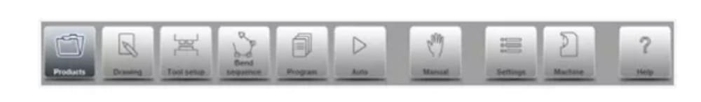
Painel de navegação
O painel de navegação é a área onde todos os principais modos podem ser encontrados. Esta área está sempre visível. Os controles, botões grandes com ícones, podem ser usados para alternar diretamente de um modo para o outro.

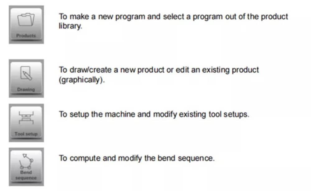
Explicação dos principais modos / botões de navegação

5. Getting started
(1)Introduction
Para obter um programa de dobra para um produto, o controle oferece a possibilidade de criar um desenho do produto e calcular uma sequência de dobra válida para o produto. Com essas informações, um programa de produto é gerado.
Isso é feito com as seguintes etapas:
● Go to the Products mode in the navigation panel and start a new product by tapping New Product.
● Insira as propriedades do produto e comece a desenhar um perfil de produto 2D no modo Desenho.
● Verifique as ferramentas, modifique ou faça uma nova configuração no modo Configuração de ferramentas.
● Use the Bend Sequence mode to determine the bend sequence by calculating it or manually modifying it upon your own idea’s.
● Quando necessário, modifique o programa numérico CNC através do modo Programa.
● Toque em Automático e pressione o botão Iniciar para produzir o produto programado.
(2)Preparations
Antes que a programação do produto possa ser iniciada, os seguintes preparativos devem ser feitos.
● The correct material properties must have been programmed in the Materials library. You can find this on the Materials page in the Settings mode.
● The correct tools must be programmed in the Tool Library. Tools are necessary to create a CNC program. You can find the libraries for the different types of tools in the Machine mode.
(3)Create a drawing
The control offers the functionality to create a drawing of the intended product. With this drawing application, tap Drawing in the navigation panel, a 2D profile or 3D product drawing is created. At this stage, there is no calculation of bends or dimensions: any profile or drawing can be created.The drawing method on the Touch screen control is based on:
● Esboçando
● Value setting
Esboçando
O esboço do produto e da forma da ferramenta pode ser feito tocando na tela nas diferentes direções que o desenho deve ter. O aplicativo seguirá o toque desenhando uma linha entre os pontos indicados. O último ponto do desenho sempre mostrará um grande ponto vermelho.
Quando o ponto de desenho estiver na tela, você pode manter o dedo nessa posição e movê-lo pela tela para mover a linha conectada em outra direção desejada ou aumentar o comprimento da linha. Este método é chamado de "Arrastar". Os valores de comprimento e ângulo ficarão visíveis na tela e podem ser ajustados para ficarem exatos ou próximos do valor desejado.
Definição de valor
Once the product or tool is drawn in the Sketching method the exact values of line lengths and angles can be optimized by the Value setting method. Just tap 2 times on the value of the line length or angle to change and the keyboard will pop-up. The value can be entered in 2 ways
of confirmation:
● Insira a função
● Função Enter-Next
The Enter function will close the keyboard after entering the value. The Enter-Next function will enter the value on the line or angle to change and the keyboard will remain opened for the next programming step.
In case the typed value is erroneous, the “undo” button right from the input field can be tapped to return to the original value or the backspace key on the keyboard to delete the last typed character.
Função de zoom
Ao pinçar a tela com dois dedos simultaneamente, é possível ampliar e reduzir a visualização do desenho, ferramenta ou máquina. Ao afastar os dedos, o sistema amplia a visualização; ao aproximar os dedos, o sistema amplia a visualização.
Ajustar à tela
Nos ícones de comando na lateral da tela, você encontrará a função Ajustar à Tela. Ela pode ser usada quando o tamanho do desenho não estiver claro na imagem. Basta tocar uma vez e o desenho completo será dimensionado para caber na tela de desenho.
Panorâmica
Ao tocar dois dedos simultaneamente e arrastá-los sobre a tela (deslizando na mesma direção), é possível deslocar o objeto na visualização 3D. Em 2D, um único dedo também permite a panorâmica.
Girando
Em 3D, a rotação da visualização do produto, ferramenta ou máquina pode ser feita com um único dedo deslizando sobre a tela.
Mais informações sobre isso podem ser encontradas no capítulo 3.
Features of the drawing tool
● Graphical design of product shapes in 2D and 3D (if available)
● Scaled sheet thickness
● Auto scaling
● Horizontal and vertical projected dimensions can be entered
● Real scale tool design
● Various machine shapes (pressbeams and tables)
● Changing of lengths and angles
● Adding or deleting of bends
● Special bend features can be applied
● Hemming bends can be programmed
● Bumping bends can be used for big radius
● Existing products can be copied, changed and stored as a new product
● Closing dimension or highest precision tolerance selection
● Connecting 2D programs for 3D-production
(4) Determine bend sequence
Após a conclusão do desenho do produto, o controle oferece o modo de configuração da ferramenta para programar a configuração exata da ferramenta, conforme organizada na máquina. Em seguida, você pode selecionar o modo Sequência de Dobra para determinar e simular a sequência de dobra necessária.
In the Bend Sequence mode, the control shows the product, the machine and the tools. In this menu the bend sequence can be programmed and checked visually. When a bend sequence has been determined, the CNC program can be generated.
More information about this can be found in chapters 4 and 5.
Cálculo de sequência de flexão
• Cálculo automático para tempo mínimo de produção
• Determinação interativa da sequência de curvatura
• Determinação manual da sequência de dobra
• Visualização de colisão do produto com ferramentas e máquinas
• Seleções livres de ferramentas e formas de máquinas
• Atribuições de tempos de giro, velocidade do batente traseiro, etc.
• Cálculo do comprimento em branco
• Indicação do tempo de produção
• Simulação de sequência de flexão
• Posições dos dedos programáveis
(5) Numerical program
O menu Programa dá acesso ao programa numérico e aos valores do produto ativo.
Existem duas possibilidades para criar um programa CNC:
• insira um programa numérico, iniciado através do modo Produtos, toque em Novo Programa, passo a passo;
• gerar o programa a partir da simulação gráfica de dobra iniciada através do modo Produtos, tocar em Novo Produto, através do modo Desenho. (ver: Modo Desenho; desenho do produto).
If the program is entered by hand, there is no collision check. All program values must be entered manually. The program depends on operator experience.
If the program is generated from a graphical bend sequence, the program can be visualised during production. A generated program can be edited according to operation needs.
Mais informações sobre isso podem ser encontradas no capítulo 6.
When a drawing has been completed with a bend sequence, and the program is stored, the program is post processed and the numerical program becomes available.
The system automatically computes :
• Força necessária
• Ajustes de máquinas como:
• Posição do eixo Y
• Descompressão
• Posição do eixo X
• Retração do eixo X
• Abertura em Y
• Eixos R
• Eixos Z
As posições dos eixos são calculadas de acordo com a configuração da máquina.
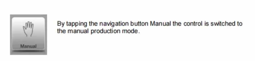
(6) The Auto menu and Manual menu, production modes
Um programa de produto pode ser executado através do modo Automático. No modo Automático, um programa completo pode ser executado dobra após dobra. No modo Automático, o modo Passo a Passo pode ser selecionado para que cada dobra seja iniciada separadamente.
O modo Manual do controle é um modo de produção independente. Neste modo, uma dobra pode ser programada e executada. Normalmente, é usado para testar o comportamento do sistema de dobra.
Mais informações sobre isso podem ser encontradas nos capítulos 7 e 8.
(7) Back-up data, external storage
Tanto os arquivos de produtos quanto os de ferramentas podem ser armazenados externamente. Dependendo da configuração, esses arquivos podem ser armazenados em uma rede ou em um pendrive. Isso facilita o backup de dados importantes e a possibilidade de troca de arquivos entre controles do Delem.
Mais informações sobre isso podem ser encontradas no capítulo 9.
6. Programming aids
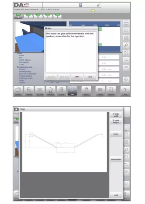
(1) Help text
Este controle está equipado com uma função de Ajuda online. Ao pressionar o botão Ajuda no painel de navegação, será fornecida ajuda contextual.
Para ativar uma janela de ajuda para um parâmetro, toque no botão Ajuda no painel de navegação.
Uma janela pop-up aparece com informações sobre o parâmetro ativo.

Esta janela de Ajuda contém as mesmas informações do Manual de Operação.
A janela de ajuda pode ser usada da seguinte maneira:
Você pode rolar o texto deslizando um dedo na direção desejada. Ao tocar na parte inferior ou superior da tela, você pode navegar pelo texto de ajuda tocando em Página Anterior / Próxima Página.
A função Índice ajuda a acessar o sumário. Os hiperlinks no sumário ajudam a navegar diretamente para o tópico desejado.
Toque em Encerrar para fechar a janela de Ajuda.
(2) Listbox functionality
Vários parâmetros no controle têm um número limitado de valores possíveis. Ao selecionar um parâmetro, ao tocar na linha de parâmetros na tela, a lista de opções será aberta perto da posição onde você tocou na linha, e o valor desejado poderá ser selecionado.

To undo the selection and the opened listbox, tapping outside the box will make it close without changing the selected parameter.
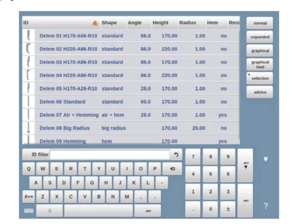
(3) Filter, live search, auto filter
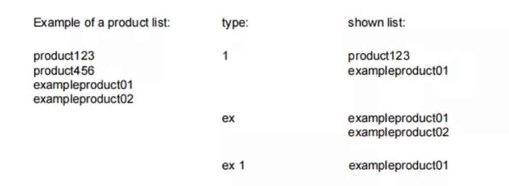
Em alguns modos, é oferecida uma lista de entidades (produtos, ferramentas, materiais, etc.). Um exemplo desse menu é o modo Produtos (seleção de produtos). Para pesquisar um produto ou ferramenta específica, pode-se usar a função de filtro. Pressione o botão de comando "Filtrar" e digite uma parte do ID no campo "Enter". Automaticamente, a lista é limitada aos itens que contêm a parte digitada.
Multiple search parts can be separated by <space>.
To close an open filter screen use the keyboard-close button on the right side next to the keyboard.
Filtro automático
In addition to the filter function the column headers of eg. the tool selection tables and the product selection table have ‘auto-filter’ functionality.
When tapping the column header one can sort the list based on that specific column. The triangle in the header is shown as an indication of the sort order.
When tapping a header with auto-filter functionality a list box will be shown automatically offering the possible options for filtering, derived from the available entries in that column. E.g.
when using this in a die selection, the V-opening can be filtered to the desired value as searched for. The list will only show dies complying the set filter.
Filters can be switched of in a similar way. The list also offers a remove filter function.

(4) Navigation
Em alguns modos, as telas do programa são divididas em guias.
The tabs can easily be selected by just tapping them. When a tab is not completely visible or not visible at all, just by dragging the tab row horizontally, the desired tab can be “pulled” in sight and be selected.
(5) Text input and editing
O cursor pode ser usado para inserir um valor ou texto específico dentro de uma entrada existente. Basta tocar na posição desejada para fazer isso. O cursor aparecerá e a entrada será adicionada ali.
E.g. in Edit notes, where multiple lines can be entered Enter is used for linefeed. Cut, Copy and Paste are offered on the keyboard for editing convenience. Undo and Redo can also be used within this editor.

The keyboard can be shown or hidden in this multiline editor using the arrow key in the lower left corner.
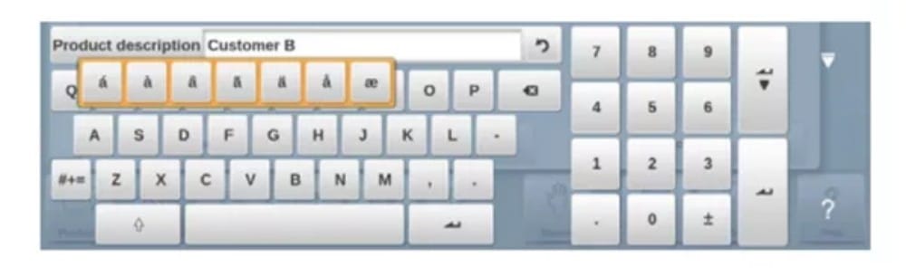
(6) Typing alphanumeric characters vs. special characters
Both alphanumeric characters and special characters can be used throughout the control. A full on-screen alphanumerical keyboard will pop up when required.
When editing a field which is pure numeric, the alphanumeric characters will be “greyed-out” and only the numerical keypad can be used. For fields which enable to use alphanumerical strings, the keyboard is completely available. Special characters as ? % – can be found using the special character button on the left-lower side of the keyboard.
Caracteres especiais (como á, à, â, ã, ä, å, æ) são suportados pelo teclado na tela mantendo um caractere (como 'a') pressionado.
(7) Calculator
The CNC control is providing a “desktop calculator” available for the operator.
At the top of the screen the calculator icon can be used to switch to calculator functionality.
The keyboard area provides calculator functions which can be used autonomously. Standard functions (add, subtract, multiply and devide) including percentage, square root, square and memory functions are available.
In case calculations should use parameter values as an input, and results as an output, one can switch to the calculator from the parameter entry. This will bring the parameter value to the calculator, and the result back to the input line.
No cutting or pasting is necessary. Only when entering and confirming the calculated value in the parameter entry line, it will be used forward.
(8) Messages centre
When messages are displayed coming from PLC, Safety systems, LUAPs or the Sequencer, these messages can be ‘send’ to the ‘Messages centre’. When a message is displayed simultaneously the message centre symbol is shown in the top row of the page header, next to eg. the calculator and keylock symbol. When tapping this message centre symbol the messages are taken from the screen, giving way for normal programming and editing.
When tapping again the actual messages are shown.
When messages are in the background, the message centre symbol has an extra indicator to show new incoming messages which are not yet shown.
(9) Network
The CNC control is equipped with a network interface. The network function offers the operators the possibility to import product files directly from the network directories or to export the finished product files to the required network directory
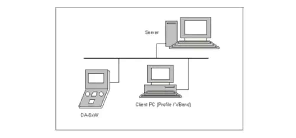
Chapter 9 about backup/restore in Settings mode contains more information about networking possibilities.
(10) Keylock function
Para evitar alterações em produtos ou programas, a função de bloqueio de teclas oferece a possibilidade de bloquear o controle.
There are two levels of locking the control. Program Lock and Machine Lock.
• In Program Lock, only a product can be selected and executed in Automatic mode.
• In Machine Lock, the machine is locked and the control can not be used.
To lock a control just tap the lock symbol in the top of the screen. Depending on the code which is used, the control will be in Program Lock or Machine Lock. Program Lock wil show a closed lock in grey. Machine lock will show the same lock but colored (red).
(11) OEM function panel
Dependendo da implementação do fabricante da máquina, o canto superior direito da tela pode ser usado para indicadores especiais.
To access functions related to those indicators, the OEM function panel can be opened by tapping this corner of the screen.
(12) Software versions
A versão do software sob seu controle é exibida na guia Informações do sistema no menu Máquina.

Produtos, a biblioteca de produtos
1. Introduction

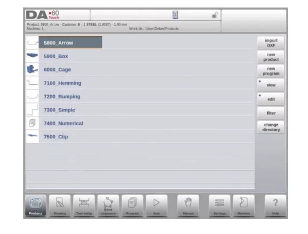
(1) The main view

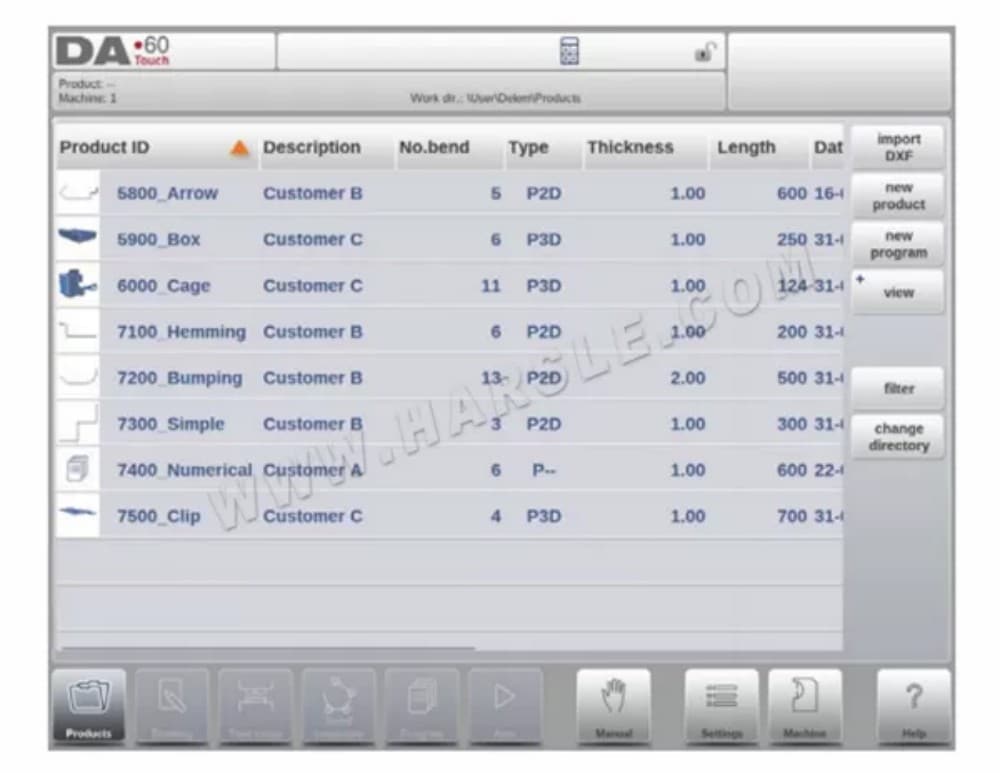
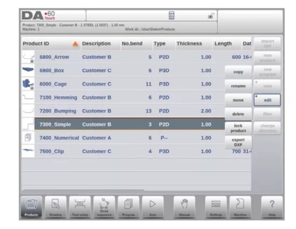
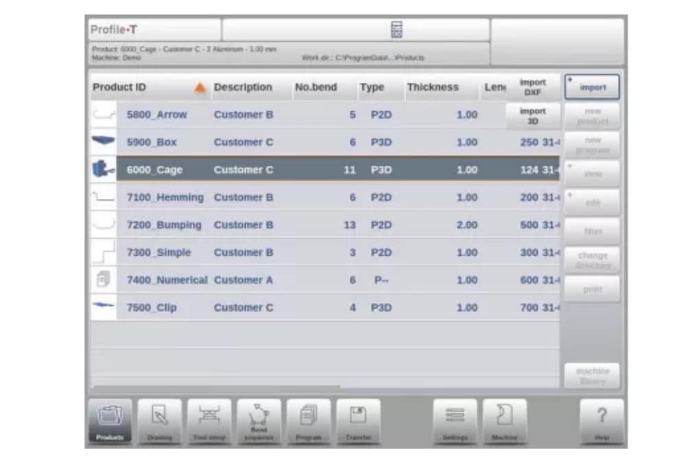
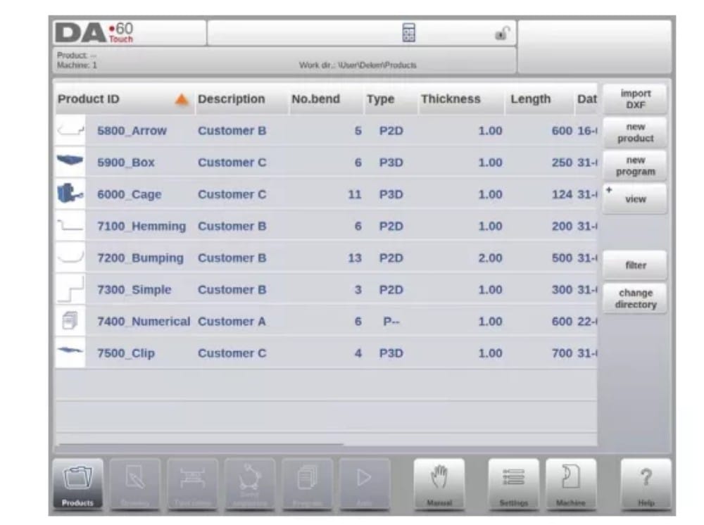
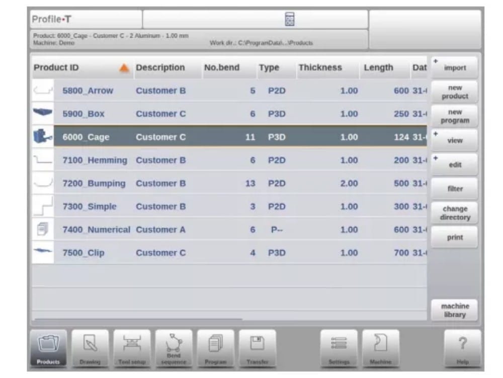
In Products mode an overview is given of the program library on the control. In this mode a product program can be selected (loaded). After that a program can be modified or executed.
Each item in the list consists of a thumbnail of the graphical product (for numerical programs a symbol is shown), its Product ID, the Product Description, the Number of bends in the product, what kind of product it is (Type) and the Date it was last used or modified.
The Type indication of the product shows following types of products:
(2) Product selection
To select a product a single tap will do. The product will be selected and loaded into the memory. From here production can be started by tapping Auto. Also navigation can start through the Products Drawing (if existing), its Tool Setup, the Bend Sequence and the numerical Program of the product.

(3) New Product, starting a new graphical product
Para iniciar um novo produto gráfico, toque em Novo produto.
Depois que o Novo Produto é escolhido, a programação do novo produto começa com seus detalhes gerais, como ID do Produto, Espessura e Material.

(4) New Program, starting a numerical program
Para iniciar um novo programa numérico, toque em Novo Programa.
After New Program is chosen, the programming starts with its general details like e.g. Product ID, Thickness and Material.

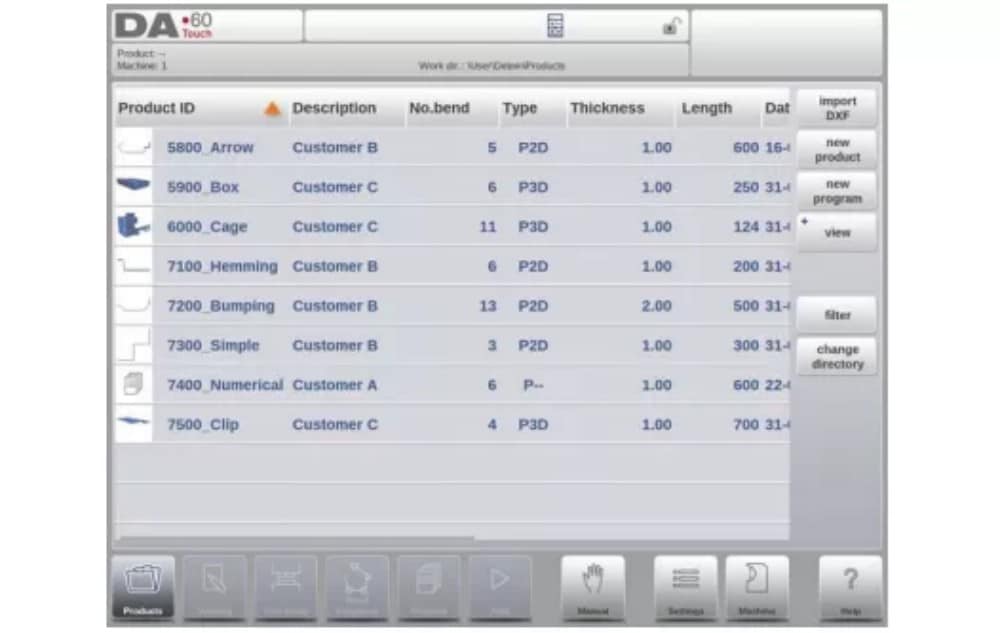
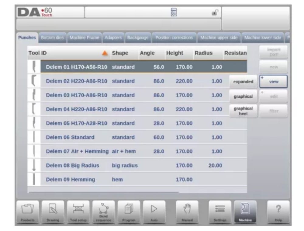
(5) Views
To view the products as a simple list, or completely graphical, the View function can be used.
By tapping View one of the three view modes can be selected.

(6) Edit, Copying and Deleting a product or program
To delete a product in the Products mode select a product by tapping it. It will be selected.
After that tap Edit and use Delete. To finally delete it confirm the question. To delete all products and programs at once, tap Delete All.

To copy a product select a product or program and tap Edit and use Copy. After this the name of the product can be programmed and the copy will be done. The product will appear in the same directory. The copied product will be an exact copy including tool setup and bend sequence if available.

(7) Product Rename and Move
Products can also be moved and renamed.This can be done in one single step: Move moves a product to a new directory, Rename allows the user to give it a new name within the same directory.
To move or rename a product select a product or program and tap Edit and choose Move or Rename from the list. For Rename a new name can be given. The product will appear in the same directory. For move a new location can be selected. The copied product will be an exact copy including tool setup and bend sequence if available.
(8) Product Lock/Unlock
A função Bloquear/Desbloquear produtos oferece um método simples para evitar alterações acidentais em programas ou produtos finalizados. Dessa forma, produtos que foram ajustados e considerados em boas condições não podem ser alterados, a menos que sejam desbloqueados.
Ao tocar em Editar, o recurso Bloquear produto/Desbloquear produto pode ser alternado para cada produto ou programa.
(9) Filter function
To make finding products easier the filter function enables live searches through-out the Products mode.
Ao tocar em "Filtrar", a tela de filtros será exibida. Ao digitar a sequência de caracteres do filtro desejado, opcionalmente separada por espaços, a busca em tempo real será iniciada.
Opcionalmente, uma visualização diferente pode ser selecionada. Além disso, a propriedade específica à qual o filtro é aplicado pode ser alterada usando Seleção.
Selections can be done on Product ID, Product Description, Type, Thickness, Length or Date.
You can either enter a complete name or number or only a part of it. If you enter part of a name and this part occurs in several product names, the control will show all product names that contain that part. It is also possible to enter a combination of name and number.
See also section 1.6.3 about Filtering and ‘Live search’.

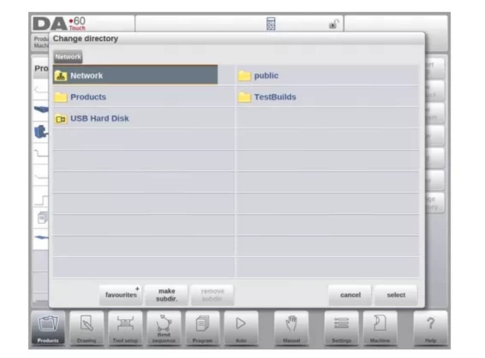
(10) Change directory
To change to a different product directory, or to add a new product directory, tap Change Directory. When an obsolete directory must be removed, select the directory and tap Remove
Directory. When a desired directory is reached, tap Select to jump back to the Products screen which will show all products in the directory. The active local directory name is displayed in the header.

(11) Network product selection
When a network directory has been mounted in the control this mounted directory can be found under Network. Network is available next to the Product directory when using change directory. The name of the mounted drive indicates availability for product selection and
armazenar.
The network directories can be navigated thru in the directory browser. Directories can be selected, added and removed and products can be selected. When a desired directory is reached, tap Select to jump back to the Products screen which will show all products in the directory. The network directory is now the active local directory. Its name is displayed in the header of the screen.
When you leave the product selection menu the control remembers the active subdirectory and the active product (if a product was selected) until another directory or product is selected.
While working with a “read-only” network, or when the network connection is interupted, the product will be saved in subdirectory “Recovered”. This can be found as a subdirectory under Products.
By tapping the Refresh button (on View) in Products mode the product library that is displayed on the screen is refreshed, which can be useful when working from a network location.
2. The DXF import option
An alternative for drawing the desired product in the control, the control can also import an externally generated CAD-system output file. This chapter will explain the use of the DXF converter to import DXF files and its functionality.
The DXF import option is started with the command button above New Product. Import DXF opens a file selection browser to select the DXF file.
Files can be located on eg. a USB stick or on the network directory. One can browse to the location and select the file.
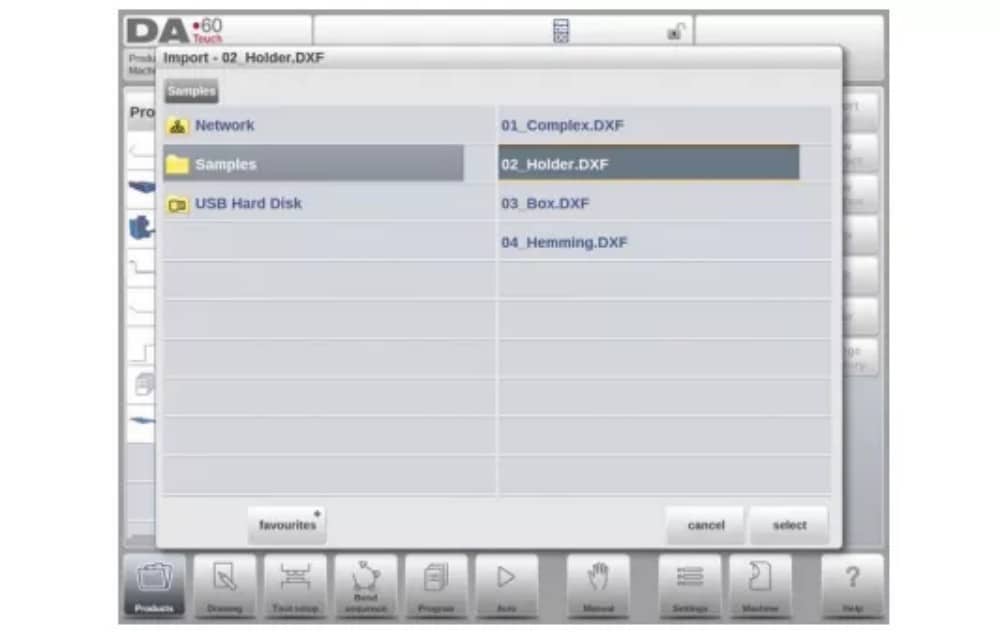
For the DXF file to be imported it is advised to create the original drawing as accurate as possible. Bend lines should be connected to contour lines to obtain an accurate product drawing. If this is not the case, the DXF Converter can correct small errors.
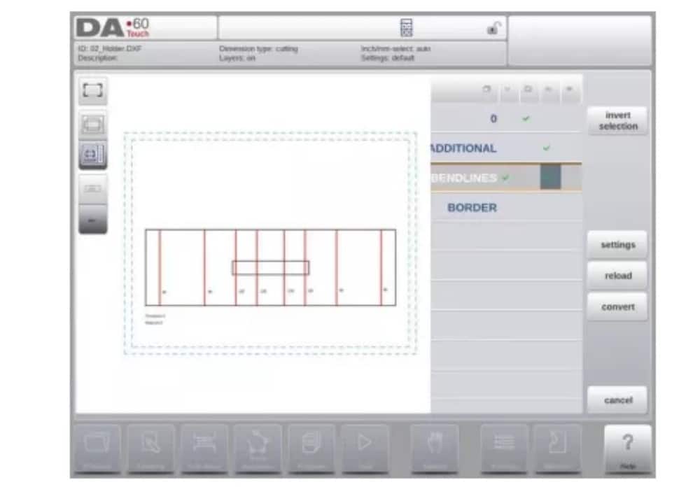
After selecting the DXF file the DXF import function window will open showing the DXF file. If this is with layer selection on, the drawing will be dashed, since no line is yet assigned to what it means.
(1) Product drawing dimensions
The drawing file can be organised in two ways:
• dimensões de projeção;
• dimensões de corte.
These ways are described in the following subparagraphs.
Durante a operação no conversor DXF, é possível alternar entre dimensões de corte e dimensões de projeção. Isso pode ser feito nas configurações de conversão DXF.
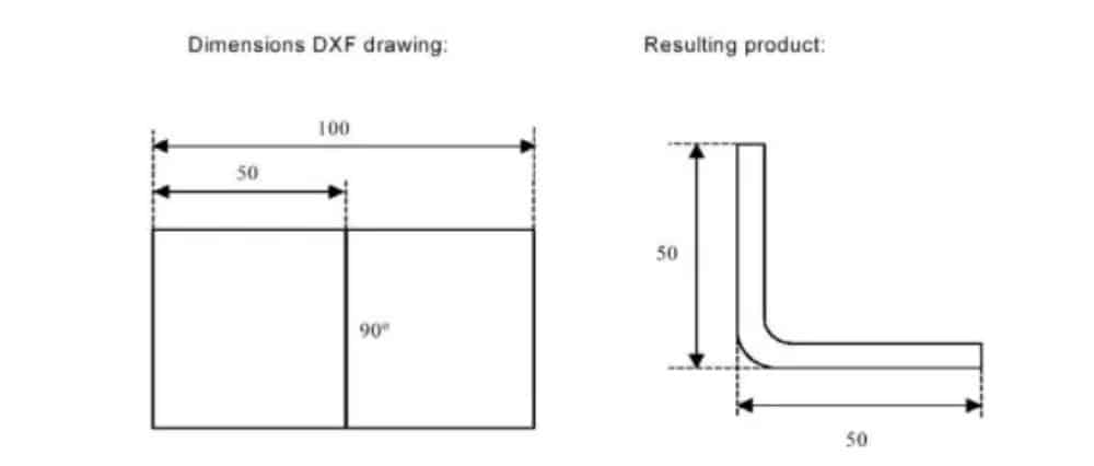
Dimensões de projeção
In this situation all product sides and bend lines have the length of the resulting product. The drawing does not represent the real size of the sheet that must be bent, but is merely a representation of how the sheet is to be organised into bends and surfaces. When such a
drawing is loaded and converted, the converter will construct a product drawing with exactly the same sizes as are present in the original drawing. Later on additional information is added about material, sheet thickness and product dimensions. It is left to the control to create a CNC program with proper axes positions that will result in a product as intended.
(2) Bendlines and Layer selection with Line assignment
Para uma conversão adequada, a atribuição de propriedades específicas do produto às linhas no DXF é importante.
Dependendo do conteúdo do DXF, as linhas de curvatura, o contorno e informações de texto adicionais podem ser atribuídos camada por camada. Caso a seleção de camadas esteja desativada, as linhas de curvatura serão pesquisadas automaticamente.
Bend line information
With the bendlines the angle information can be defined via text near the line. The text labels,
to be configured in Settings::Labels, can be used as follws:
• Default: normal air bending with a positive or negative value
• Hemming: an H followed by a positive or negative value of the pre-bend angle.
• Radius: an R followed by the value of the radius.
Definição:
• positive value: the flange bends upwards,
• negative value: the flange bends downwards.
Informações do produto
Beside the actual product drawing a DXF drawing can contain other information, such as manufacturer name, dimension lines, product description etc. If this information is organised in other layers than the product drawing then this information can be filtered out by selecting only certain layers for conversion. Otherwise, it possible to remove unnecessary information in the converter program before conversion of the drawing is started.
Seleção de camadas
Depending on the DXF import settings, which can be entered from the mainscreen, layer selection can be set on or off.
In case of layer selection on, the layer property list visualisation can be switched. The buttons in the left top corner enable this choice. Following paragraphs describe the difference between
Layer selection switched on and Layer selection switched off.
(3) Conversion
When the assignments have been set properly, conversion can be executed by tapping the Convert button.
The conversion preview will be shown when there are warnings or errors.
During conversion the DXF drawing is represented by lines like contour line, bend line and inside contour lines. Colors indicate the property for the line conversion.The lines of the product drawing will have different colours after the conversion. Every colour has its own meaning:
• Azul: Linha de contorno, esta linha é uma parte do contorno externo do produto.
• Vermelho: Linha de curvatura, esta linha é uma curvatura.
• Verde: Contorno interno, esta linha faz parte do contorno interno do produto.
• Preto: os textos atribuídos serão exibidos em preto.

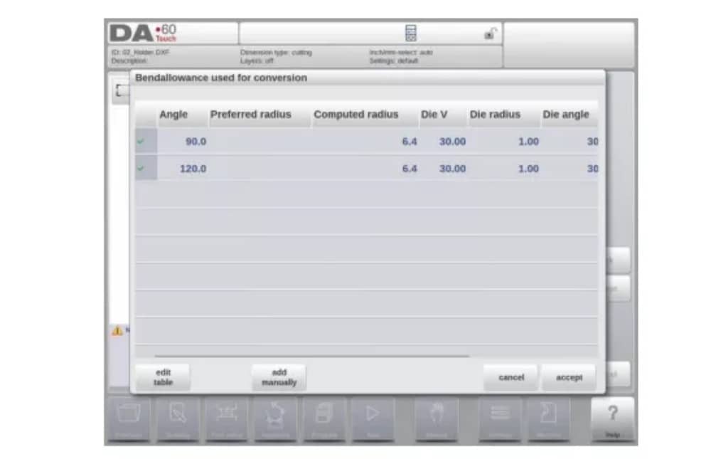
(4) Converting cutting dimensions, with bend allowance info
No último estágio da conversão de um DXF com dimensões de corte, a margem de curvatura que foi usada durante o desdobramento precisa ser reutilizada na conversão.
Therefore the conversion of cutting dimensions will always use the bend allowance table of the control and it will check if for all bends bend allowance information is available.
In case there is just one set of bend allowance parameters available for each bend, this will be used. The bend allowance pop-up will show the angles from the product with the found bend allowance. If more entries in the table can be valid, one needs to select the appropriate bend allowance line. The prefered and calculated radius can be helpful in this selection.
Adding Bend Allowance information manually
In case the bend allowance information is given with the DXF cutting dimension drawing, included in the DXF or as separate info, there is the possibility to manually enter this information.
When a DXF is imported and the bend allowance value per bend is included (based on the bendline info) these values are imported and used with the desired bend. The control will use this as an input which overules the bend allowance calculation or table search of the control.
If this information is entered during the DXF conversion, this will work equivalently, bypassing the controls calculation or table search.
If the desired bend allowance information is not present from the table, one can also manually add the information just before actual converting. In case the bend allowance is not given before or during the DXF conversion this will be automatically prompted. One can select either to select from excisting entries from the bend allowance table, or enter bend allowance just for this conversion.
To enable the function of programming bend allowance information in the Drawing function of the control (bend property) this needs to be switched on in the product properties. This is automatically done in case of importing.
(5) DXF Settings
Nas configurações do conversor DXF, os parâmetros de conversão podem ser configurados. É possível armazenar vários arquivos de configuração para tipos de desenho específicos. As funções "Salvar como" e "Carregar" estão disponíveis.
Conversion parameters

3. The 3D import function (Profile-T3D offline only)
An alternative for drawing the desired product in the application is to import an externally generated CAD-system file. With the 3D import function Profile-T3D can import the generic .IGES and .STEP files.
This chapter will explain the use of the 3D import functionality for.IGES and .STEP files.
(This functionality is solely available in Profile-T3D)
The 3D import function is started via the Import command button above New Product. Import 3D opens a file selection browser to select an .IGES or .STEP file.
(1) Conversion

The conversion can be started by tapping Convert. This will start the interpretation of the 3D design into a product with bendlines and sheetmetal specific characteristics.
The application will show the product with the designated bendlines.

In case the converter does not find any imperfections the conversion is previewed and one can finalize the conversion with tapping Accept.
From here the product is converted and shown in Drawing mode.
One can continue with tool selection and bend sequence programming.

The 3D CAD file requirements
For the .IGES and .STEP files to be imported it is important to meet the constraints for sheet metal product designs. The constraints are available upon request at Delem.
The 3D file to be imported must of course be generated with the objective to design a sheet metal part which can be processed on a press brake.
4. The DXF contour export option
As part of the DXF-option the Export DXF function, on Edit in Products mode and on Transfer (Profile-T), enables the export of any product including the bend deductions as a contour. This contour is stored as a DXF and holds the cutting dimensions.

Desenho do produto
Para iniciar um novo desenho de produto, escolha Novo Produto na biblioteca de produtos
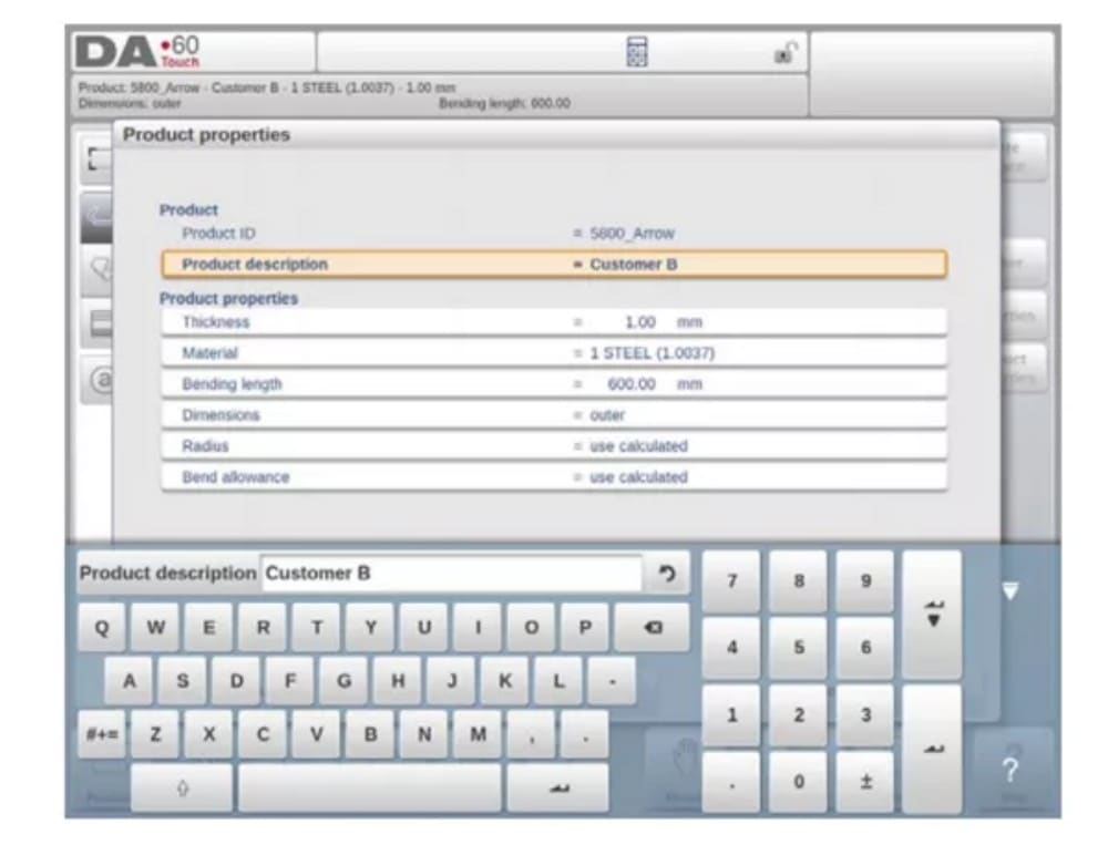
When a new product drawing is started a screen with general product properties appears.
First these properties, general data, should be set before starting with the product drawing.
(1) Add Notes
Ao clicar em Editar Notas, uma nova janela será exibida, na qual você poderá editar o texto sobre o produto atual. Os caracteres possíveis serão exibidos no teclado.

2. 2D product drawing
(1) Introduction
Após inserir os dados gerais do produto, a tela de desenho é exibida.
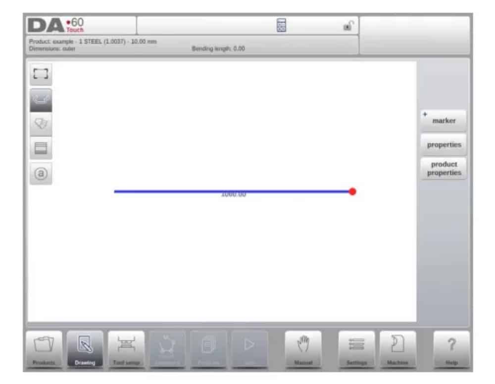
Na linha de informações superior, você encontrará informações sobre ID do produto, descrição do produto, seleção de dimensões internas/externas e diretório atual do produto.
Now you can create the profile of the product. It is possible by using your fingers to tap and create quickly the product in ‘sketch’ mode. After that the real product dimensions and corresponding values can be entered by using the keyboard.
It is also possible to directly enter the angle of the bend followed by the length of that side by using the keyboard and the Enter button. The properties are prompted in the input bar of the screen on the keyboard panel. This procedure continues until the product has the desired profile.
Os dados do produto podem ser alterados selecionando Propriedades do Produto. As propriedades dos ângulos e linhas do produto podem ser alteradas selecionando Propriedades.
Configuração da ferramenta
1. Introduction
2. Standard procedure
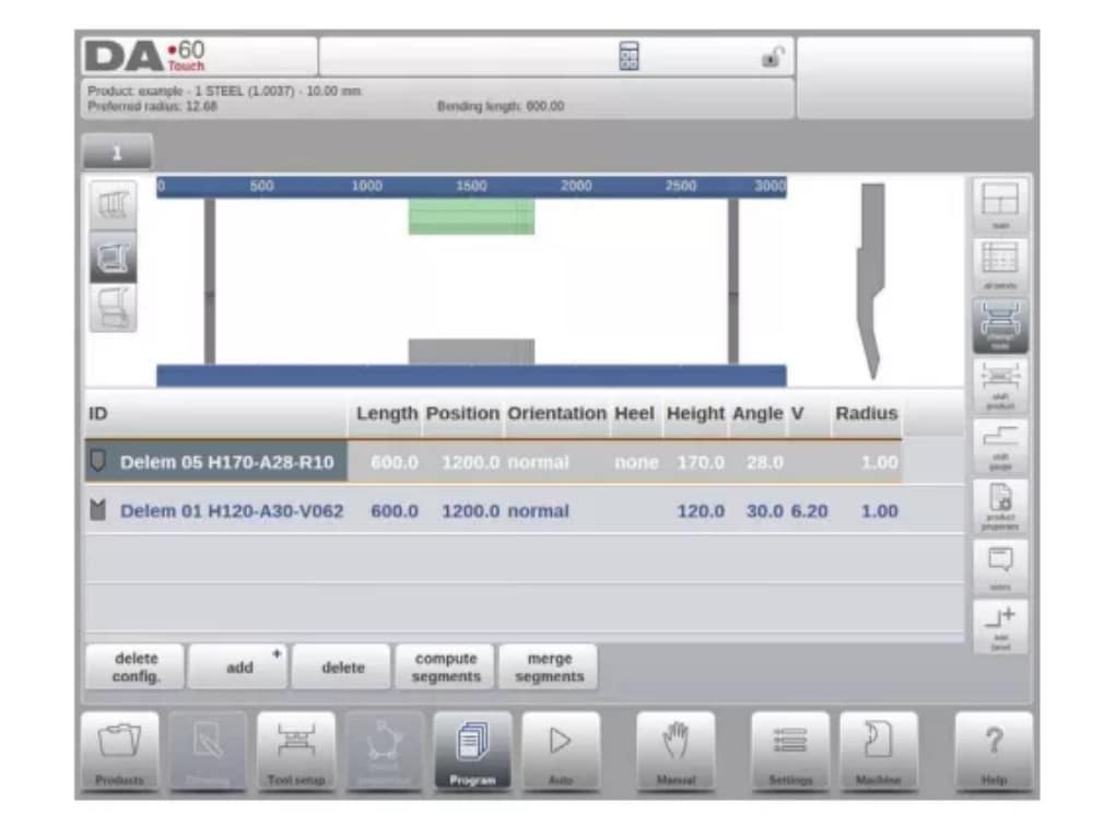
Quando a função Configuração de Ferramentas é ativada, a tela mostra uma vista frontal da configuração da máquina na metade superior. Na metade inferior, são exibidos os dados da ferramenta. Nesta tela, é possível programar o posicionamento das ferramentas na máquina.

3. Tool selection
When starting a new tool configuration, the machine opening is empty

Select Add to add a tool to the configuration; punch, die or adapter (if enabled)

Quando uma ferramenta é escolhida (por exemplo, um punção), ela é colocada na máquina com o comprimento máximo disponível.

Após uma ferramenta ser posicionada, a ID da ferramenta pode ser alterada selecionando a ID do punção na tela e tocando na visualização de lista.
4. Tool segmentation
Ao usar ferramentas segmentadas, a partir das quais ferramentas de tamanho desejado podem ser compostas, o controle pode dar suporte a isso e ajudar a gerar a segmentação apropriada.

In below paragraph the functionality for segmentation is explained, including the use of the three views on the tool setup. Next to the Tool Setup screen the ability to have segmentation features available is depending on the programmed segments for each tool. This
programming can be done in Machine mode under the Punches and Bottom dies libraries.
More on programming of segments in the Tool library can be found at the end of this paragraph.
Na tela de Configuração da Ferramenta, há três modos de visualização disponíveis. Com os botões de seleção no lado esquerdo da vista frontal da máquina, é possível escolher as seguintes vistas:
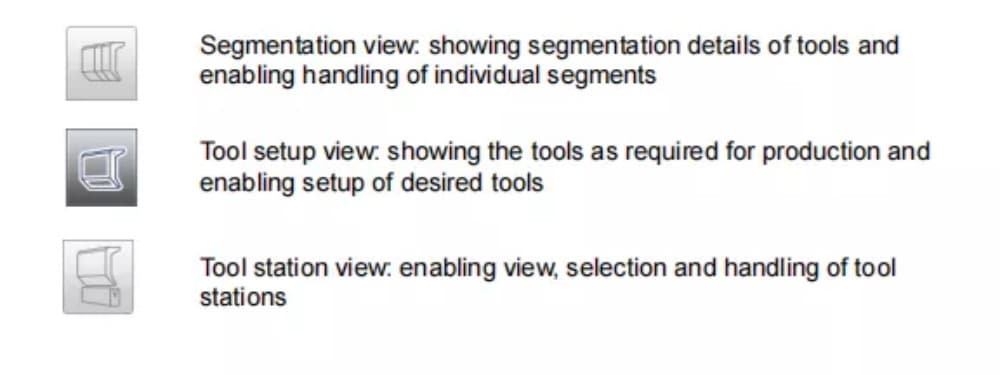
5. Segmentation of individual tools
After the proces of setting up the desired tools for the products to be made, the Bend
Sequence mode can calculate the most efficient bend sequence.
Upon desire the tools can be segmented, helping in the selection of the segments creating the correct tool length.
The tool segmentation function automatically calculates the required segmentation and uses the assignments “maximum inter tool distance” and upon choice the “tool length tolerance” for finding the best solution

6. Station selection and repositioning
A terceira visualização da Configuração de Ferramentas é a Visualização de Estação. Na Visualização de Estação, todas as estações de ferramentas são destacadas quando selecionadas e podem ser reposicionadas programando uma posição alternativa ou arrastando-as para a nova posição desejada na máquina.
A toolstation is automatically defined when there is an overlap from punches with dies. This, meaning that a toolstation is considered a station when e.g. there is an exact position of punch and die opposite of each other. When there is a shifted position but still overlap in
between punch and die, this is still considered a tool station. Even when two punches are opposite of a single die, which can be useful bending constrained bends, this is considered a toolstation. These stations can be repositioned without losing their relative positioning.

A visualização da estação não altera nada nos detalhes da ferramenta.
Sequência de Curvatura
1. Introduction

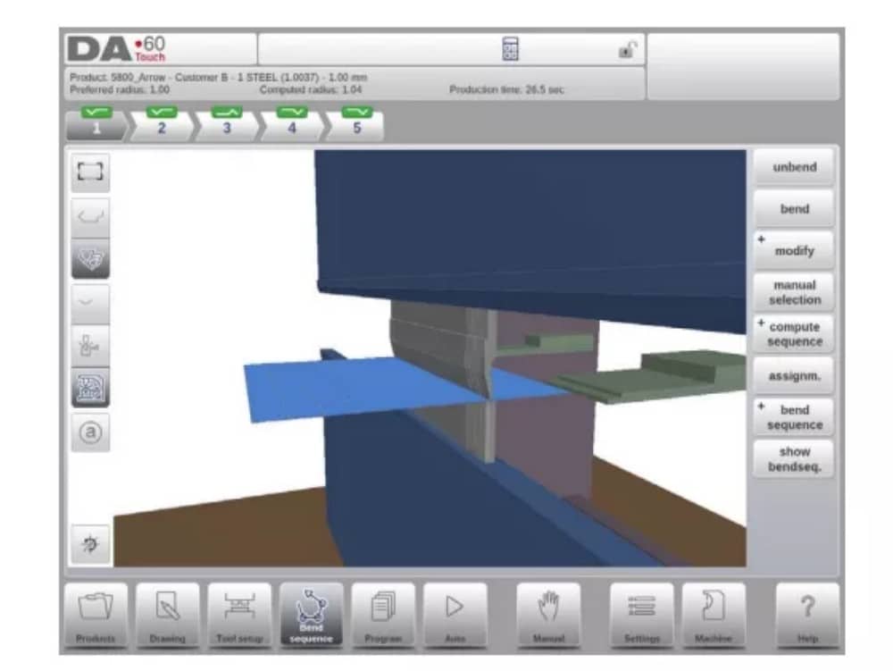
Quando uma configuração de ferramenta estiver disponível, a simulação de dobra pode ser iniciada para determinar uma sequência de dobra para o produto ativo. A determinação da sequência de dobra é iniciada tocando no botão de navegação "Sequência de Dobra".

The bendsequence determination can be realised by automatic calculation starting with the bent product. It is also possible determining the sequence manually starting with the flat
product, not using the automatic calculation.
Na tela de sequência de dobras, o produto aparece entre as ferramentas em uma possível posição final de dobra. Ao iniciar a simulação, o produto é exibido em seu estado final. Para obter uma sequência de dobras, o produto deve ser desdobrado da última dobra para a primeira. Isso pode ser feito com as teclas de função disponíveis.
Quando for preferível começar com um produto desdobrado para escolher manualmente a sequência de dobra, isso pode ser feito no botão de comando Sequência de dobra.
(1) View select
Within the bendsequence screen views can be switched upon required choice.
The view functions are located oposite of the command buttons in the main screen.
Funções de visualização

(2) Bend selector
Na tela de sequência de curvas, as curvas podem ser selecionadas e navegadas com o seletor de curvas. Na parte superior da tela, o número de curvas é indicado com seletores de curvas preliminares. Após a conclusão da sequência de curvas, todas elas ficam coloridas, ativas e exibem um indicador de curva.

A partir daí, as curvas podem ser facilmente selecionadas com um toque. No seletor de curvas, o indicador de curva será exibido nas cores verde, amarelo ou vermelho para indicar o nível de conformidade com as atribuições da sequência de curvas.

2. Unbend product
Para gerar um programa CNC, a sequência de dobra deve ser conhecida. Há duas maneiras de fazer isso:
• Pressione a tecla de função Compute. O controle calculará automaticamente o valor mais rápido
possível sequência de dobra para este produto.
• Pressione a tecla de função Desdobrar repetidamente, até que o produto esteja completamente desdobrado.
Quando o produto estiver completamente desdobrado, pressione a função Sequência de dobra e Salvar para gerar e salvar o programa CNC.

3. Manual selection of bends
Normally the control proposes the next (un)bend in a sequence. This is computed by the control depending on the programmed assignments and of course the product shape and applied tools. For various reasons it can be necessary to choose another bend for the bend sequence. The bend sequence can be changed/determined through the function Manual
Selection. When the function Manual Selection has been choosen, a new window is opened.

4. Assignments
(1) Introduction
The Assignments are parameters with which the bend sequence computation is controlled.
The assignments screen is opened from the tool configuration screen with the function key
Assignm.
Automatic bend sequence computation works with several conditions in order to find an optimum between a minimum production time, handling possibilities without product/machine and product/tool collision.
In order to find one of the optimums you must program several computation parameters with which the bend sequence can be computed. Some of these parameters are machine-related and some are related to product accuracy, handling possibilities and turn times.
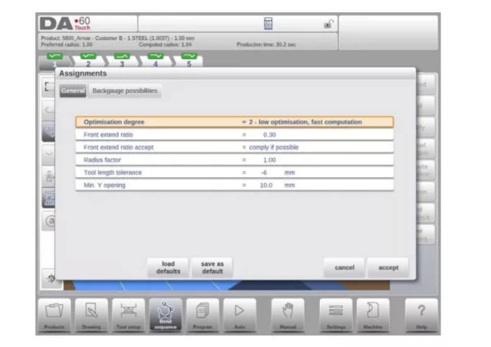
(2) Assignments – general
Grau de otimização
Faixa de 1 a 5.
O número de alternativas a serem computadas para cada curva deve ser inserido aqui.
Quanto maior esse número, mais alternativas devem ser examinadas pelo controle, portanto, maior será o tempo de computação:
1 – menor otimização, computação mais rápida
2 – baixa otimização, computação rápida
3 – otimização média, computação média
4 – alta otimização, computação lenta
5 – maior otimização, computação mais lenta
(3) Assignments – Backgauge possibilities

5. Show bend sequence
Quando a função Mostrar sequência de dobra é pressionada, uma visão geral gráfica da sequência de dobra é exibida.

Esta opção pode ser chamada a qualquer momento após a primeira desdobragem. A visão geral gráfica exibe as dobras determinadas, bem como as ainda não determinadas (ponto de interrogação).
Cada imagem na visão geral pode ser ampliada ou reduzida separadamente com as funções disponíveis. As imagens também podem ser giradas com o movimento dos dedos.
Programação de produtos
1. Introdução

To edit an existing CNC program, select a product in the Products overview and select the navigation button Program. When starting a new program, select New Program and after giving in the main product properties and tool setup, the system will automatically switch to Program.
In both cases, a screen as shown above should appear. Programming and changing data is done in the same way in both cases.
The main screen shows the existing numerical program or, when starting a new program, the first to be programmed bend. The bend selector in the top of the screen can be used to navigate thru the bends. The indicated bends can be tapped to easily select the desired bend data.
At the side of the main screen views and functions are indicated with command buttons.
Funções
Os seguintes modos/funções estão disponíveis:

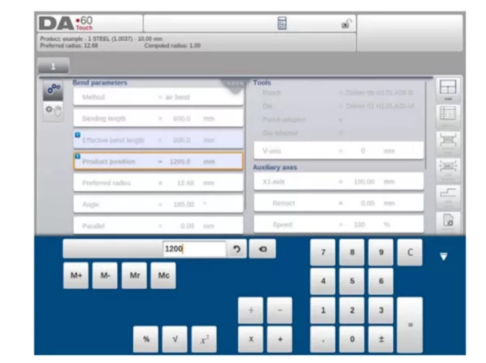
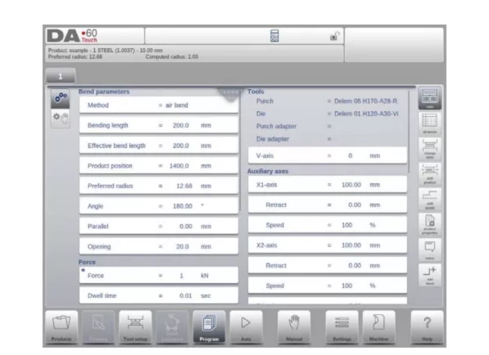
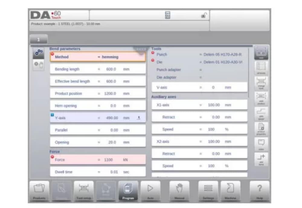
2. Program mode, parameter explanation
A tela principal mostra as dobras disponíveis e, a partir desta tela principal, de cada dobra disponível, parâmetros específicos podem ser visualizados e editados.
O ID do produto e a descrição do produto são exibidos na linha superior da tela.
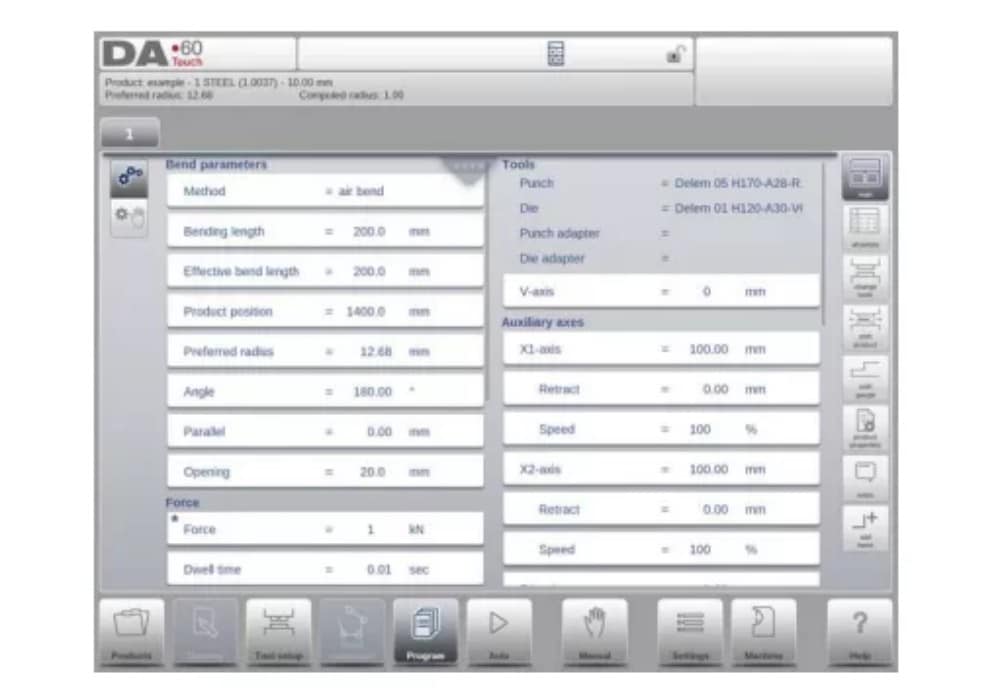
No caso de um produto gráfico, informações gráficas também podem ser exibidas.
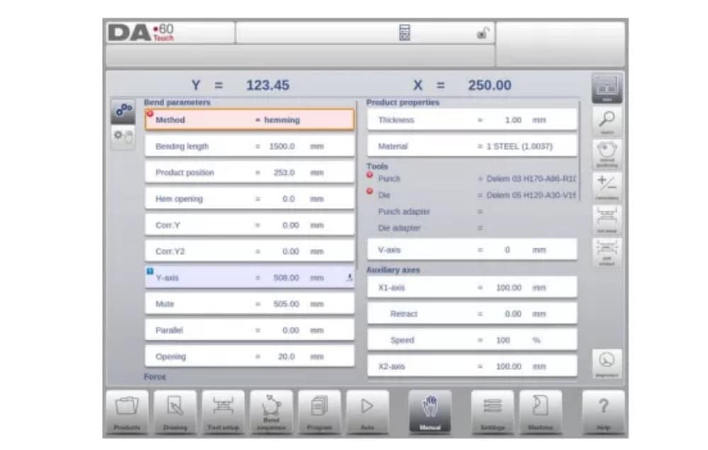
(1) Bend parameters
Métodos de dobra

(2) Force
Vigor
Força máxima ajustada durante a prensagem (calculada automaticamente).
Tempo de permanência
Tempo de retenção do punção no ponto de flexão.
Velocidade
Velocidade
Velocidade de trabalho (velocidade de prensagem). Inicialmente, o valor deste parâmetro é copiado do parâmetro Velocidade de Prensagem Padrão no modo Configurações.
Funções
Repetição
0 = a flexão é ignorada
1 a 99 = número de vezes que essa flexão será repetida.
3. Edit / view modes
(1)All Bends
When the function All Bends has been pressed, a complete overview of the bends appears.

From within this screen, the complete CNC program can be edited. All bend parameters can be edited within the table and bends can be swapped, moved, added and deleted.
The available columns can be scrolled by finger movement / swipe.
(2) Change tools
Para alterar as ferramentas, o menu Configuração de Ferramentas pode ser usado. Ao usar o modo Programa para programação numérica, a Configuração de Ferramentas será usada como padrão. Se a configuração da ferramenta precisar ser alterada para apenas uma etapa de dobra, o botão Alterar Ferramentas pode ser usado. O controle sempre perguntará se as alterações devem ser feitas em toda a configuração ou apenas para uma dobra. Se for necessária a configuração completa da ferramenta, o menu Configuração de Ferramentas será alternado automaticamente para.
4. Programming parameters
Parameters in program mode can be programmed one by one. The effect of the parameter on other parameters can be computed either automatically or manually. This depends on the selected mode on the left-hand side of the screen. The Auto Computation switch enable to select between:
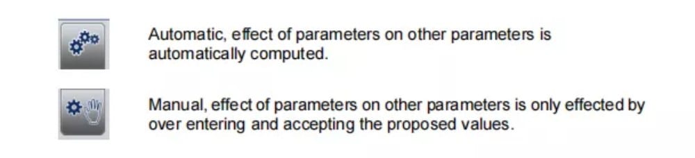
A relação entre os parâmetros é visualizada com um símbolo e uma cor de fundo.
Modo automático
1. Introdução
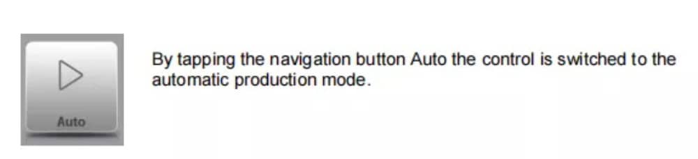
No modo automático, com o programa ativo, a produção pode ser iniciada. Após entrar no modo automático, o botão Iniciar pode ser pressionado e a produção pode começar.
The automatic mode executes the program automatically bend by bend after pushing the Start button. When selecting a different product in Products mode, which is in the library and has already been used for production, one can immediately switch to Auto and start production.
Every time after a different bending program is selected you must check your tools and tool positions in your machine. This is also indicated with a ‘check tools’ warning message when you enter the automatic mode.
2. View modes
The auto mode screen is offering a diversity of views which, depending on ones production methode, can be chosen. When selecting auto mode for the first time, the main screen will appear. On the right side of the screen the available view modes can be selected.
Os seguintes modos de visualização estão disponíveis:
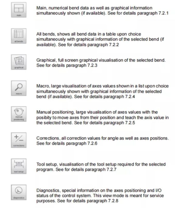
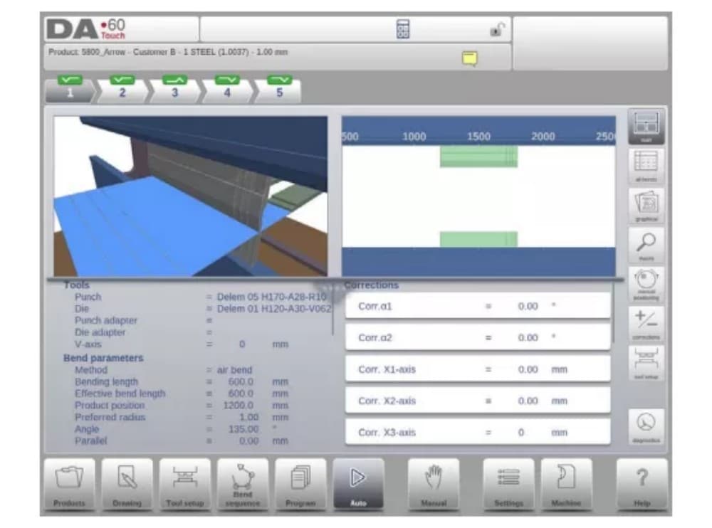
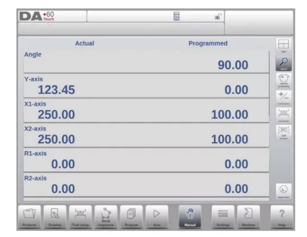
(1) Main
Main view shows the numerical data of the bend along with the corrections. The corrections can be programmed here. The splitter control devides the screen in graphical visualisation and the numerical data. This can be closed if only numerical data is required.
(2) All bends
The all bends view mode shows, with or without the opened graphical pane, a table including all bend data. The bends are shown row wize and the columns display all bend parameters.

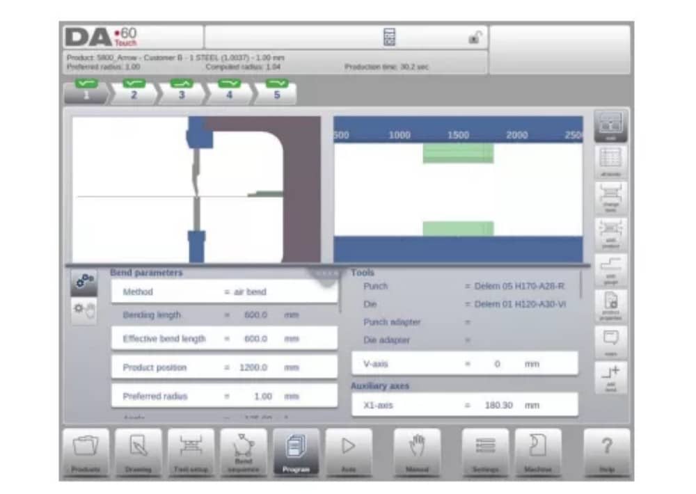
(3) Graphical
No modo de visualização gráfica, é fornecida uma visualização gráfica em tela cheia do processo de dobra.

(4) Macro
With macro view mode, the control switches to a view with only large axes values on the screen. This view can be used when working a little remote from the control, still able to read the axes values.

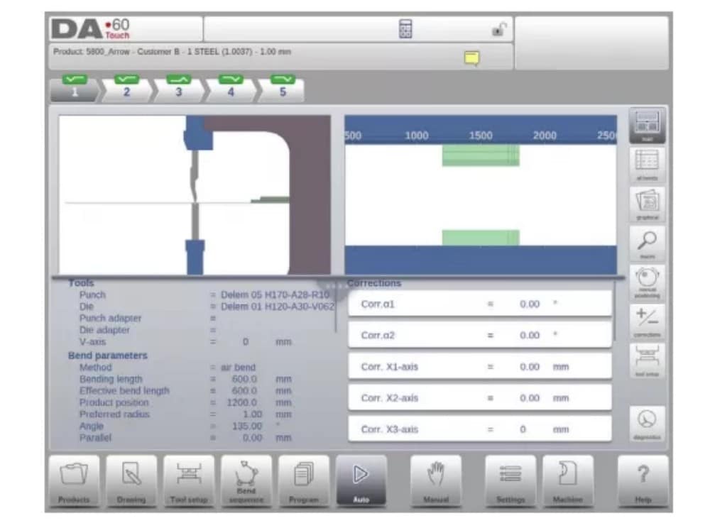
(5) Manual positioning
In manual positioning view mode the axes values are shown at large. Axes can be selected and while selected the position can be controlled by turning the handwheel.
O indicador de ensino:

When the teach indicator arrow is pressed, standing in between actual value and programmed value, the value is tought to the program step
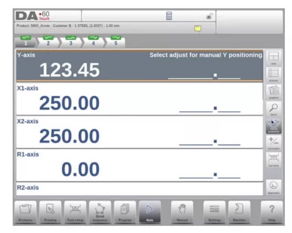
3. Notes
The notes which can be added to a product or program can be viewed in Automatic mode.
With the presence of the notes indicator its indicated that notes are added to this product and by tapping the indicator these will be shown.
Notas podem ser adicionadas de forma geral a um produto ou programa, mas também a itens específicos. Documentos PDF também podem ser incluídos nas notas. O botão PDF abrirá o documento.
4. Bumping correction
In case of a selected bumping bend a general correction for a bumping bend can be entered. This function is only available if a product is loaded that contains a bumping bend.
Com Bumping Corr. aparece uma nova janela na qual a correção pode ser inserida.

Modo manual
1. Introdução
No modo manual, você programa os parâmetros para uma dobra. Este modo é útil para testes, calibração e dobras individuais.
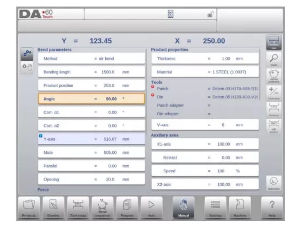
O modo manual é independente do modo automático e pode ser programado independentemente dos programas na memória.
2. Programming parameters & Views
Os parâmetros no modo manual podem ser programados um a um. O efeito do parâmetro sobre outros parâmetros pode ser calculado automática ou manualmente. Isso depende do modo selecionado no lado esquerdo da tela. A chave de Computação Automática permite:
selecione entre:
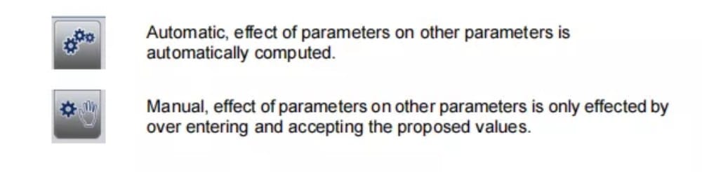
A relação entre os parâmetros é visualizada com um símbolo e uma cor de fundo.
3.Macro
Com o Macro, o controle alterna para uma nova visualização com apenas valores de eixos grandes na tela. Essa visualização pode ser usada ao trabalhar um pouco distante do controle, ainda permitindo a leitura dos valores dos eixos.
4. Manual movement of the axes
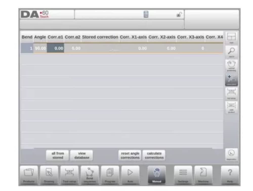
5. Corrections
Neste modo de visualização, as correções para a dobra programada no modo Manual são mostradas. Como se trata sempre de uma única dobra, uma única linha será exibida.
6. Diagnostics
When tapping Diagnostics, the control switches to a view which shows axes states. In this window, the current state of available axes can be observed. This screen can also be active while the control is started. As such, it can be used to monitor the control behaviour during a bend cycle.

Configurações
1. Introdução

The Settings mode of the control, which can be found in the navigation panel, gives access to all kind of settings which influence the programming of new products and programs.
Default values and specific constraints can be set.
As configurações são divididas em várias abas, organizando logicamente os diferentes assuntos. Nas seções a seguir, as abas disponíveis e as configurações detalhadas são discutidas.

2. General
Selecione a aba desejada e toque no parâmetro a ser alterado. Quando os parâmetros tiverem um valor numérico ou alfanumérico, o teclado aparecerá para inserir o valor desejado. Quando a configuração ou o parâmetro puder ser selecionado em uma lista, a lista aparecerá e a seleção poderá ser feita.
feito por toque. Listas mais longas permitem rolar verticalmente para verificar os itens disponíveis.
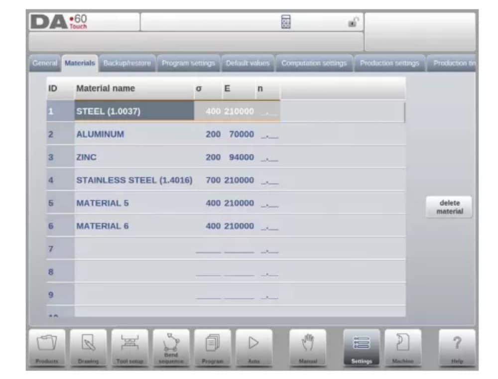
3. Materials
Nesta aba, os materiais e suas propriedades podem ser programados. Materiais existentes podem ser editados, novos materiais podem ser adicionados ou materiais existentes podem ser excluídos. No máximo 99 materiais podem ser programados no controle.
4. Backup / restore
This tab offers the possibilities to backup and restore products, tools as well as settings and tables. When products or tools originate from older control models, the DLC-file format products and tools can also be restored using this specific restore function.
For materials a specific backup and restore are available here.
Ferramentas e produtos podem ser copiados e restaurados de acordo com os procedimentos a seguir. Os procedimentos para salvar ou ler dados são semelhantes para todos os tipos de mídia de backup: por exemplo, rede ou pendrive.

The actual backup directory consists of a device (USB stick, network) and a directory. The choice of devices depends on which devices have been connected to the control. If necessary, directories can be created and selected. The backup locations for storage of products and tools can be set independently.
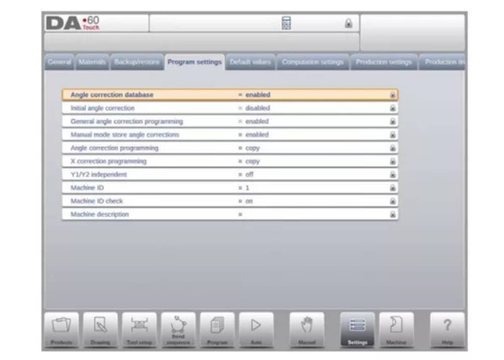
5. Program settings
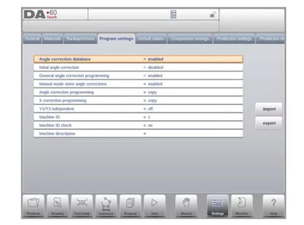
Banco de dados de correção de ângulo
Parâmetro para habilitar o banco de dados com correções de ângulo.
6. Default values
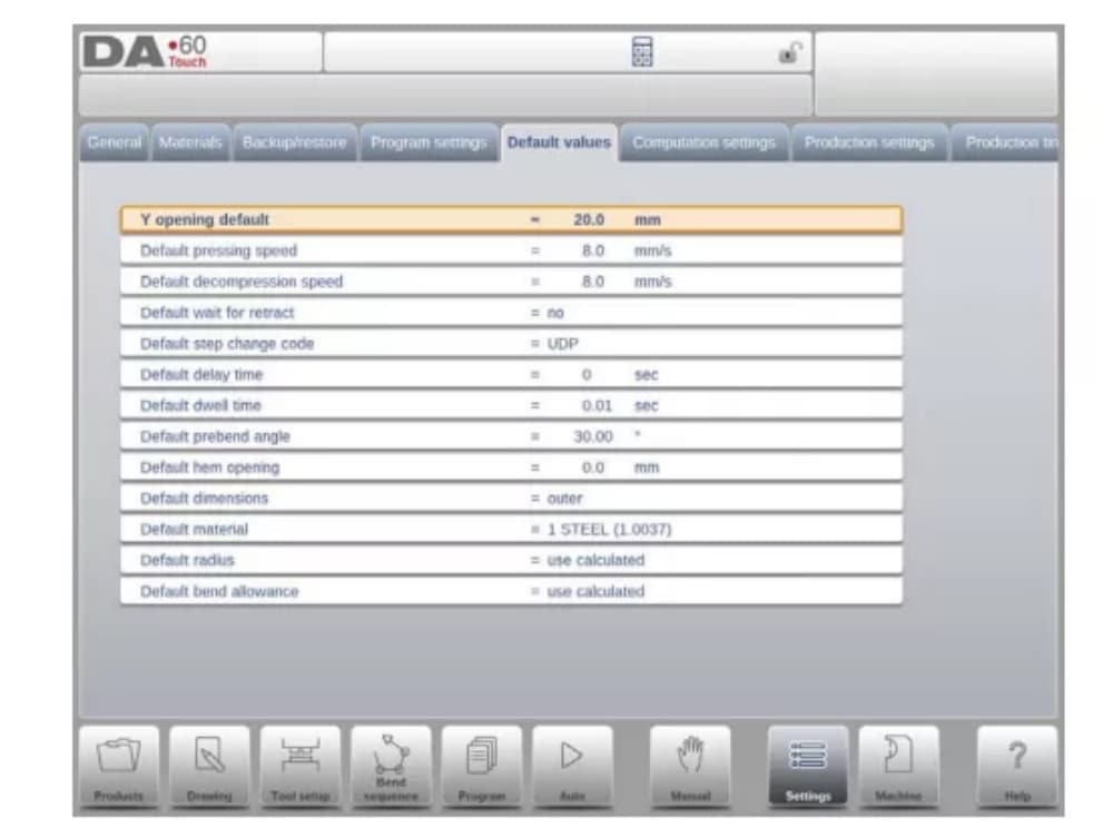
Y opening default
Default Y-axis opening, used as initial value for the parameter ‘opening’ in a new program.
7. Computation settings
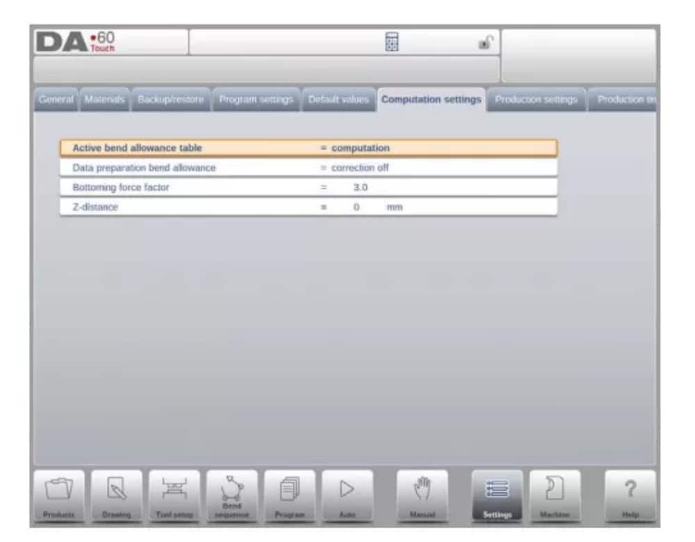
Tabela de tolerância de curvatura ativa
computation => the control will calculate the bend alowancetable => the bend allowance table will be used
Bend-allowance is the correction of the X-axis due to sheet shortening after bending.
With this parameter the method for bend-allowance calculation is chosen. ‘Computation’ means the standard formula of the control is used to calculate the bend-allowance.
‘Table’ means a bend-allowance table with correction values can be used.
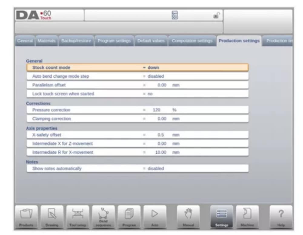
8. Production settings
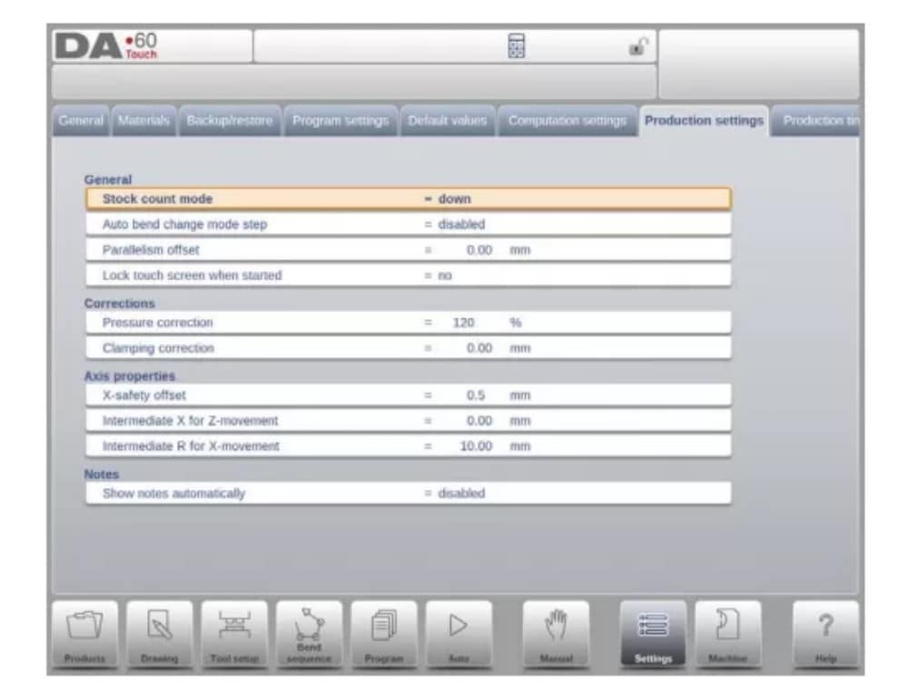
Modo de contagem de estoque
Configuração para o contador de estoque no modo de produção, para que o contador de estoque (contador de produtos) faça a contagem crescente ou decrescente.
When down counting is selected, the stock counter in production mode is decremented after each product cycle. When the counter has reached zero, the control is stopped. On
the next start action, the stock counting value is reset to its original value.
When up counting is selected, the counter is incremented after each product cycle.
Down counting can be useful if a pre-planned quota must be produced. Up counting could be used to give a report on production progress.
9. Production time calculation
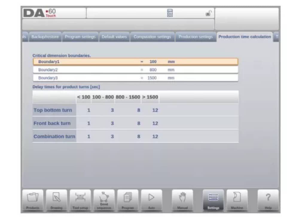
The parameters on this page are used to calculate the production time for a product in the bend sequence computation process. This production time depends on the positioning speed of the axes and the product handling times. The positioning speed is depending on machine settings.
10. Time settings

Tempo de exibição
Exibe data e hora no painel de título, somente hora ou nenhuma hora.
Máquina
1. Introdução
The Machine mode of the control, which can be found in the navigation panel, gives access to the configuration items of the machine and specific machine characteristics which influence generic calculations and machine behaviour.
As configurações são divididas em várias abas, organizando logicamente os diferentes assuntos. Nas seções a seguir, as abas disponíveis e as configurações detalhadas são discutidas.
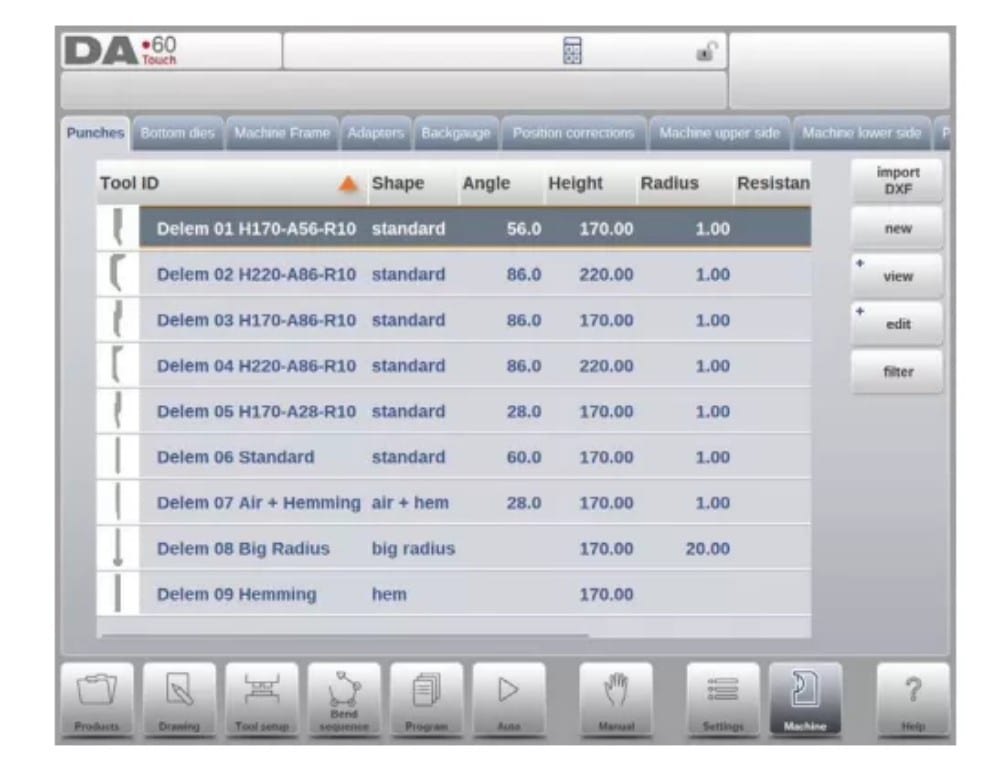
2. Programming of Punches
Nesta aba, os punções utilizados na máquina podem ser programados. Novos punções podem ser adicionados; os existentes podem ser editados, copiados, renomeados e excluídos.
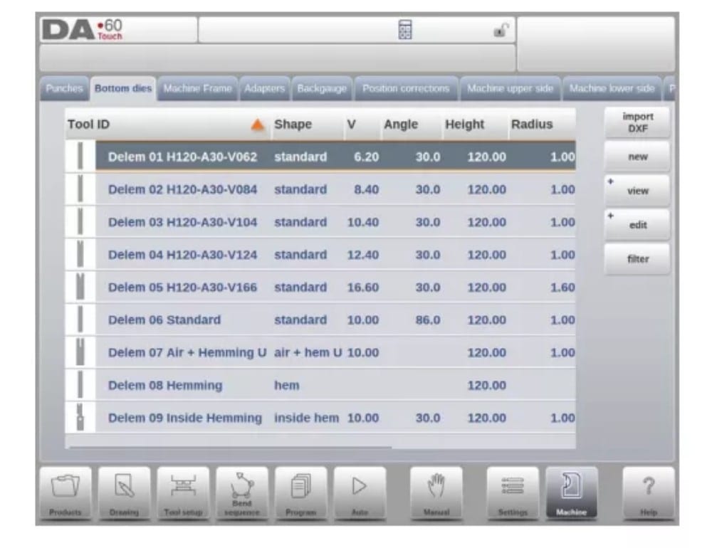
3. Programming of bottom dies
In this tab, the bottom dies used in the machine can be programmed. New dies can be added; existing dies can be edited, copied, renamed and deleted.
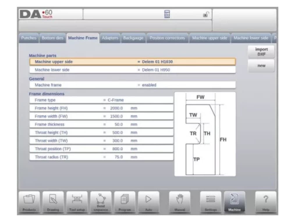
4. Machine frame
Nesta aba, as geometrias ativas da máquina, da viga superior e inferior e das estruturas laterais, podem ser selecionadas e definidas. A identificação da máquina também pode ser programada aqui.
Além do Lado superior da máquina e do Lado inferior da máquina, que podem ser escolhidos entre os disponíveis, as dimensões da estrutura lateral podem ser programadas nesta página.
O formato da máquina é mostrado na tela de simulação durante a programação gráfica e usado para detecção de colisão da peça de trabalho contra a máquina.
5. Adapters
Nesta página os adaptadores de ferramentas podem ser habilitados e programados.
Upon choice upper adapters as well as lower adapters can be enabled. The default adapter, which will be chosen when an adapter is added to the tool setup, can also be set.
Ao adicionar um adaptador, primeiro é preciso fornecer os parâmetros básicos com base em um modelo. Na segunda etapa, os detalhes do adaptador podem ser desenhados como qualquer outro punção ou matriz.
6. Backgauge
Com as dimensões do pino do batente traseiro, o movimento do eixo R e o movimento do eixo X relacionado são levados em consideração. Além disso, a colisão entre a peça e o batente traseiro é calculada usando as dimensões.
7. Position corrections

8. Machine upper side
Nesta aba, a geometria da máquina para a viga superior, como um perfil, pode ser programada. Essas informações são utilizadas na detecção de colisões entre o produto e a máquina.
When e.g. utilities are added to the machine in special cases, these can be programmed as a special machine shape to enable the collision calculations to take this into account.
In most instances there is only one shape programmed.
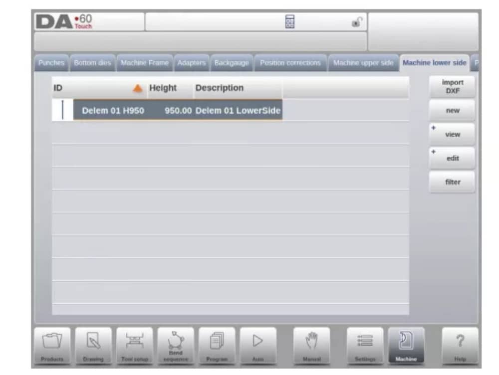
9. Machine lower side
Nesta aba é possível programar a geometria da máquina para o lado inferior (mesa), como perfil.
This information is used in the collision detection of collisions with product and machine.
When e.g. utilities are added to the machine in special cases, these can be programmed as a special machine shape to enable the collision calculations to take this into account.
In most instances there is only one shape programmed.
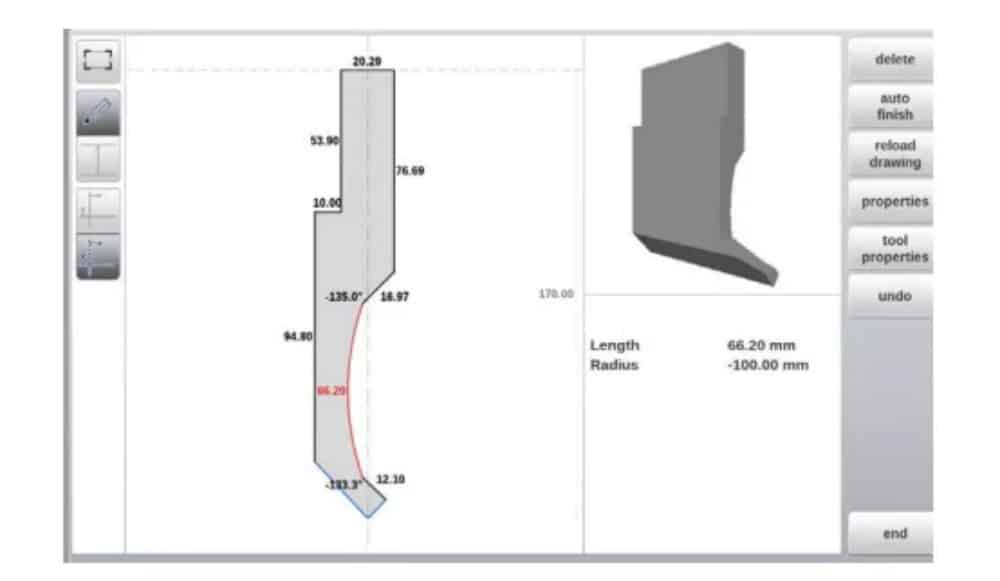
10. Drawing functionality for tools, adapters and machine shapes
In programming punches, dies, adapters and also machine shapes, after the main data the control provides the functionality to freely draw the desired shape in the object. This
functionality makes the objects appear more realistic but most of all enables the control to do an accurate collision prevention.
11. DXF import for tools, adapters and machine parts
Within the tool library, Punches, Bottom dies, Adapters as well as the machine shapes, Machine upper side, Machine lower side and Machine Frame, one can find the optional DXF
import function. This function enables the import of the contour from a DXF file.
Import DXF opens the file browser enabling the selection of the DXF file of the desired shape.

12. Protractor

13. Event logging
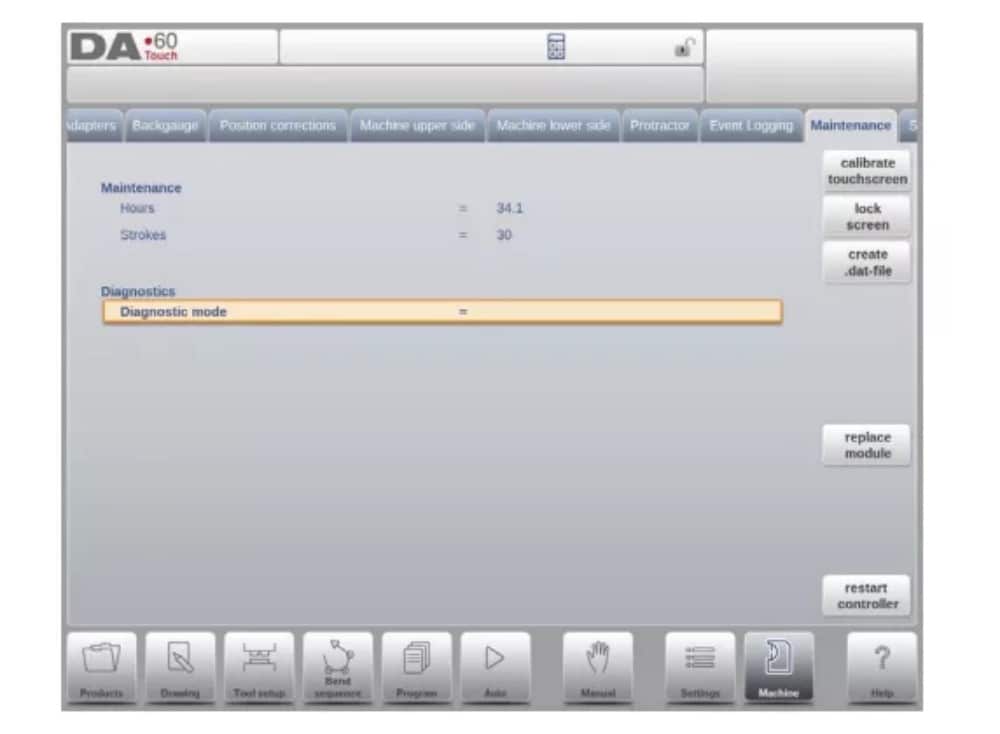
14. Maintenance
On this tab maintenance related functions are located. Next to the machine hour counter and the machine stroke counter also functions to help replace modules and to store diagnostic data can be found here.
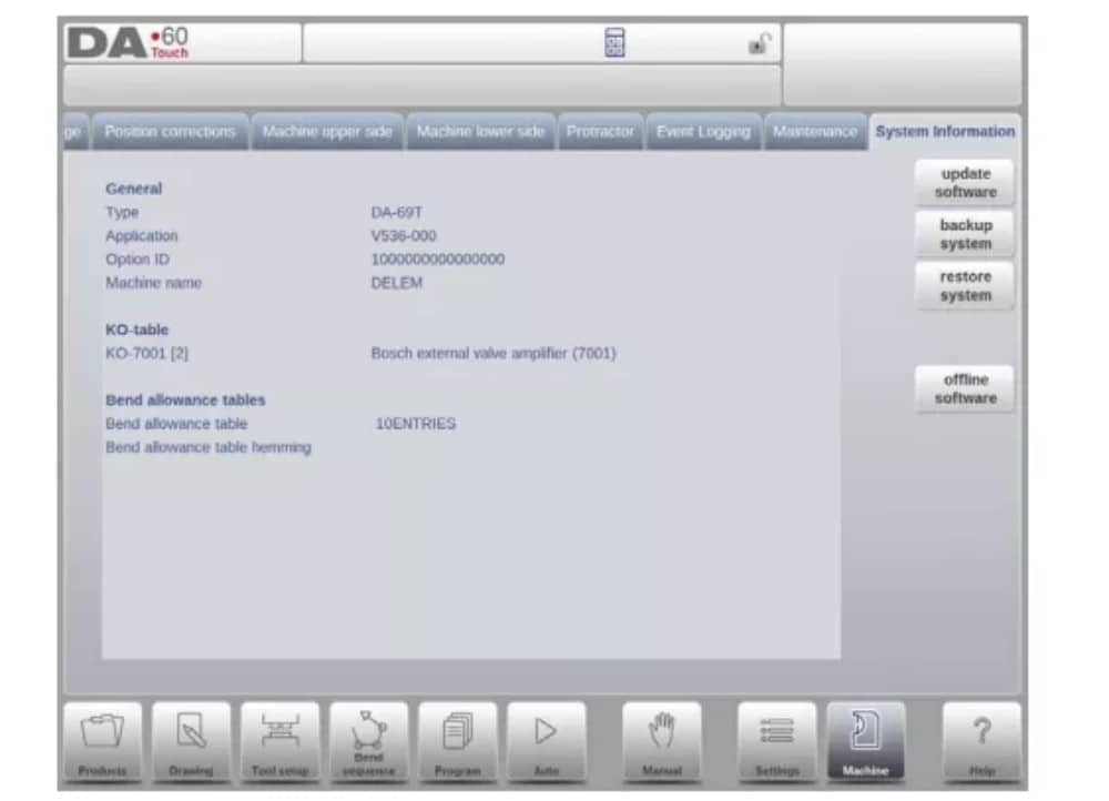
15. System information
Nesta aba, você encontra informações do sistema. Além das informações sobre a versão do software, também é possível ler os IDs dos módulos instalados e a versão dos arquivos específicos do OEM.
Além das informações, a funcionalidade de atualização de software também está disponível aqui.
Perfil-T
1. Introdução
(1) General
O programa offline Profile-T oferece uma interface de usuário semelhante à de um controle de linha DA-Touch. Os capítulos anteriores, que descrevem a operação e o uso do controle DA-Touch, devem ser usados como referência para o uso deste software offline. Este capítulo se concentrará em algumas funções especiais disponíveis apenas no software Profile-T.
(2) System requirements
To run Profile-T on a computer it should at least be equipped with the following features:
• PC compatível com IBM;
• Minimum Screen resolution of 1024×768
• Windows XP / Windows 7;
• Leitor de CD-ROM (somente para sistemas distribuídos em CD-ROM);
• Free USB port
(3) Profile-T distribution & manuals
Depending on the purchase package the Profile-T software is distributed on a CD-ROM or can be generated at the control.
2. Profile-T operation
(1) Profile-T principle
The next figure shows the start page of Profile-T:
(2) Machine library
It is important that the parameters in Profile-T are the same as in the control on the machine.
In this way the offline generated programs are 100% compatible with the control system. In Profile-T you install several machines in order to use 1 offline programming station for the complete machine range on the production floor.
(3) Print functionality (Profile-T2D and Profile-T3D only)
In Products mode it is possible to generate a print out of the selected product (Profile-T 2D and Profile-T 3D only). When pressing the button ‘print’ the standard Windows printer menu is opened to select the desired printing device and printer settings
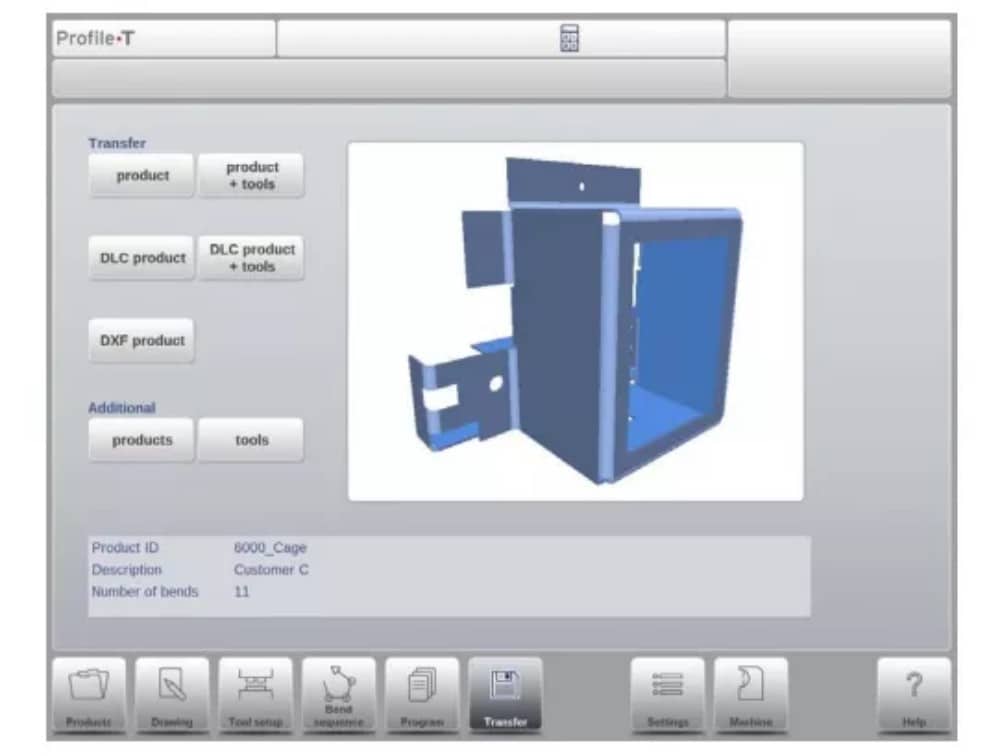
(4) Transfer mode
Quando o design do produto e a geração do programa CNC estiverem concluídos, esses dados podem ser transferidos no modo de transferência para, por exemplo, um dispositivo de memória USB.