


Se desideri migliorare l'efficienza e la precisione delle operazioni della tua pressa piegatrice, è fondamentale capire come ottimizzare la modalità macchina DELEM DA-69T. In qualità di protagonista nel campo dei sistemi di controllo CNC, il DELEM DA-69T offre una piattaforma solida per la gestione di complesse operazioni di piegatura dei metalli.
In questa guida, ti guiderò attraverso strategie e tecniche essenziali per massimizzare le prestazioni del tuo DELEM DA-69T Machine Mode. Che tu voglia migliorare la produttività o la precisione, questo articolo ti fornirà gli spunti necessari per ottenere il massimo dalla tua macchina.
Introduzione alla modalità macchina
Per accedere alla modalità Macchina sul DELEM DA-69T, toccare il pulsante "Macchina" nel pannello di navigazione.
Questa modalità è fondamentale per configurare le impostazioni che influiscono sul comportamento e sui calcoli della macchina. Le impostazioni sono organizzate in diverse schede, tra cui è possibile navigare toccando e trascinando orizzontalmente, se necessario.
Questa configurazione consente una gestione efficiente della configurazione della macchina in base alle proprie esigenze.
Programmazione dei punzoni e muore
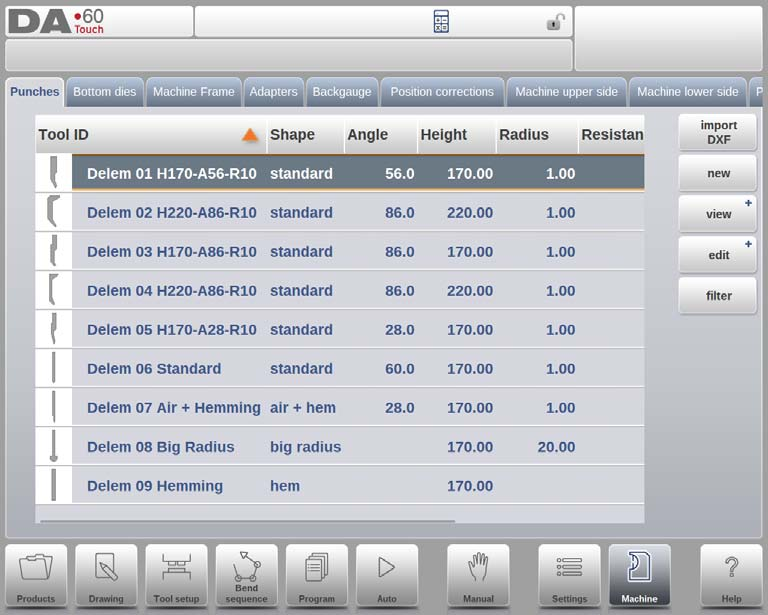
Per programmare in modo efficace punzoni e matrici in modalità macchina DELEM DA-69T, è necessario iniziare navigando nell'interfaccia di controllo per aggiungere, modificare o eliminare i dati di punzoni e matrici. Per prima cosa, è necessario accedere al database, dove è possibile inserire nuovi punzoni e matrici, modificare i record esistenti o rimuovere voci obsolete.
Il sistema offre diverse viste, come quella espansa, quella grafica e quella con tallone grafico, consentendo di visualizzare le configurazioni di punzone e matrice in modo completo. La vista espansa offre dati dettagliati, mentre la vista grafica mostra una rappresentazione visiva e la vista con tallone grafico si concentra sull'allineamento del tallone, facilitando una programmazione e una configurazione precise.
Comprensione del telaio della macchina e modifica del contorno
Quando si tratta di personalizzare la modalità macchina DELEM DA-69T, è fondamentale capire come utilizzare in modo efficace l'editor di contorni C-frame. Questa funzionalità consente agli operatori di adattare e personalizzare il telaio della macchina in base a esigenze specifiche, migliorando sia la precisione che la funzionalità durante le operazioni.
Telaio della macchina
Nel sistema DELEM DA-69T, la linguetta del telaio della macchina svolge un ruolo centrale nella definizione delle geometrie attive della macchina, comprese le travi superiori e inferiori e i telai laterali.
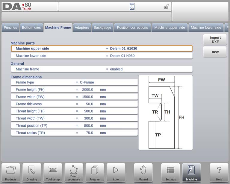
Qui è possibile programmare l'identificazione della macchina e impostare le dimensioni fondamentali per una simulazione accurata e il rilevamento delle collisioni. Ogni componente, dal lato superiore della macchina alla tavola inferiore, può essere personalizzato utilizzando la funzione Filtro Vista sulla tastiera, semplificando il processo di selezione.
È importante considerare come i telai della macchina interagiscono con la sequenza di piegatura. Ad esempio, i telai laterali situati all'esterno della zona di piegatura potrebbero non influire sul rilevamento delle collisioni e, se necessario, potrebbero essere esclusi dalla simulazione di piegatura. Per impostazione predefinita, la simulazione dei telai è abilitata, ma sapere quando disattivarla può migliorare l'efficienza operativa.
Il tipo di telaio laterale predefinito è un telaio a C, sebbene sia possibile scegliere un telaio a O se più adatto al design della macchina. Dimensioni chiave come altezza, larghezza, spessore del telaio e parametri di gola (altezza, larghezza, posizione e raggio) sono fondamentali per la configurazione del telaio. Inoltre, il DELEM DA-69T supporta anche l'importazione DXF, consentendo un caricamento preciso delle forme, integrando il già flessibile editor di contorni per telai a C.
Editor di contorni a C
L'editor di contorni del telaio a C è uno strumento potente all'interno di questo sistema. Offre all'utente la possibilità di disegnare e modificare i contorni del telaio in dettaglio, creando un design personalizzato che riflette specifiche esigenze operative.
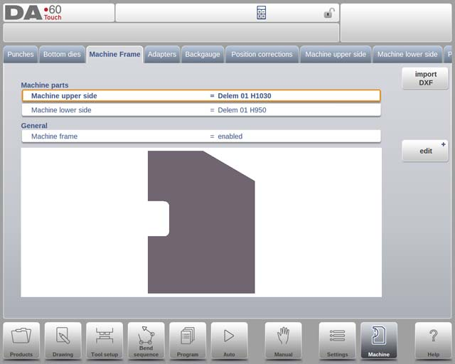
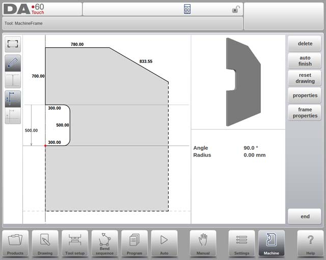
Dalla regolazione delle forme base all'incorporazione di raggi nei segmenti di linea, questa funzionalità offre un livello avanzato di personalizzazione che sostituisce la tradizionale programmazione parametrica del telaio. Sfruttando questi strumenti avanzati, gli utenti possono ottimizzare la configurazione del telaio della macchina, ottenendo in definitiva una maggiore precisione e una maggiore versatilità applicativa nei loro progetti di lavorazione dei metalli.
Adattatore
In questa pagina è possibile abilitare e programmare gli adattatori per utensili, siano essi superiori o inferiori. È possibile impostare un adattatore predefinito, che verrà selezionato automaticamente quando un adattatore viene aggiunto alla configurazione dell'utensile. Inizialmente, è necessario fornire i parametri di base basati su un modello, seguito dal disegno dettagliato dell'adattatore, in modo simile alla progettazione di qualsiasi punzone o matrice.
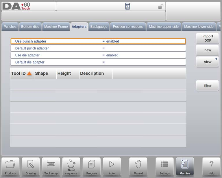
Importazione DXF (facoltativa)
La forma di un adattatore può essere importata anche tramite la funzione opzionale di importazione DXF, standard nel DA-69T e opzionale nel DA-66T.
Punto di montaggio (facoltativamente programmabile)
Nel disegno, troverete il punto di montaggio dell'adattatore, indicato da una freccia triangolare, che mostra il punto di collegamento alla trave di pressatura o al tavolo. Una seconda freccia indica dove verrà posizionato il punzone o la matrice in questo adattatore. Questi punti di montaggio sono presenti anche nei punzoni/matrici e nella trave di pressatura/tavolo. Se questa funzione non è abilitata, gli indicatori non verranno visualizzati.
Adattatori predefiniti per utensili
È possibile impostare adattatori predefiniti per gli strumenti che utilizzano comunemente un adattatore specifico. Se impostato come predefinito nelle proprietà dello strumento, l'adattatore viene caricato automaticamente nella configurazione dello strumento ogni volta che lo strumento viene selezionato.
Utilizzo della funzionalità Backgauge
Con le dimensioni delle dita del registro posteriore si tiene conto del movimento dell'asse R e del relativo movimento dell'asse X. Anche la collisione tra pezzo e registro posteriore viene calcolata utilizzando le dimensioni.
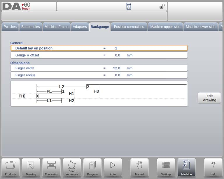
Posizione di appoggio predefinita
Questa è la posizione di appoggio predefinita nel caso in cui sia necessario utilizzare una posizione di appoggio durante il calcolo automatico della sequenza di piegatura, ad esempio nel caso in cui la posizione dell'asse X sia al di fuori dell'intervallo consentito o maggiore del 'limite di arresto di appoggio'; non viene utilizzata quando si seleziona manualmente un livello di appoggio.
Significato dei numeri lay-on:
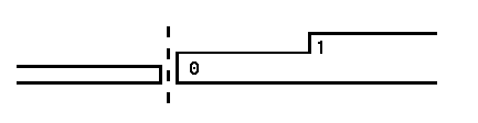
Appoggio = 0
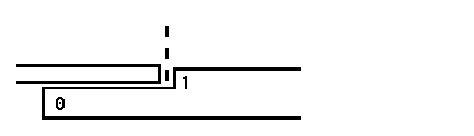
Appoggio = 1
Offset calibro R
È possibile impostare un valore di offset per l'asse R se il registro posteriore è posizionato contro il bordo del foglio e la posizione dell'asse X è al di fuori della zona di sicurezza della matrice.
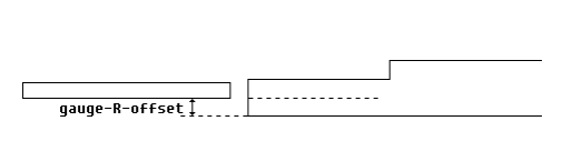
Un valore negativo indica una posizione del registro posteriore più bassa. Questo offset è valido solo per la posizione del registro 0.
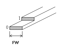
Larghezza del dito
Larghezza del dito del registro posteriore. Disponibile solo quando sono installati gli assi Z automatici.
Toccare Modifica disegno per visualizzare il disegno del registro posteriore in cui è possibile programmare le dimensioni del dito del registro posteriore.
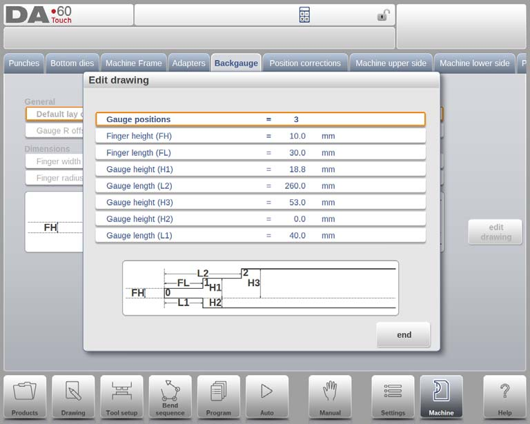
Le dimensioni del registro posteriore e delle posizioni di appoggio dipendono dal numero di posizioni di registro programmate, con un massimo di quattro. Regolando questo parametro, viene visualizzata una nuova finestra per programmare le dimensioni delle dita. I parametri includono:
- Posizioni del calibro: È possibile impostare fino a quattro posizioni, che influenzano le opzioni di programmazione disponibili.
- Altezza del dito (FH): Lo spessore della punta del primo dito del registro posteriore.
- Lunghezza del dito (FL): La lunghezza del primo livello del dito.
- Altezza del calibro (H1/H3/H4): Le altezze dei vari livelli delle dita.
- Lunghezza del calibro (L2/L3): Le lunghezze per i livelli di sovrapposizione aggiuntivi.
- Altezza del calibro (H2): L'altezza nella parte inferiore dell'indicatore.
- Lunghezza del calibro (L1): La lunghezza del livello del dito inferiore.
L'illustrazione sullo schermo si aggiorna per riflettere il numero di posizioni del misuratore programmate, facilitando così una configurazione e delle regolazioni precise.
Dito del registro posteriore biblioteca
Quando si programmano più set di riscontri di registro posteriori nella modalità macchina DELEM DA-69T, questi vengono memorizzati in una libreria di riscontri. I riscontri speciali attivano un database che consente di impostare più set di riscontri. Quando si sceglie un prodotto, è fondamentale selezionare i riscontri di registro posteriori che corrispondono al programma CNC utilizzato per la macchina.
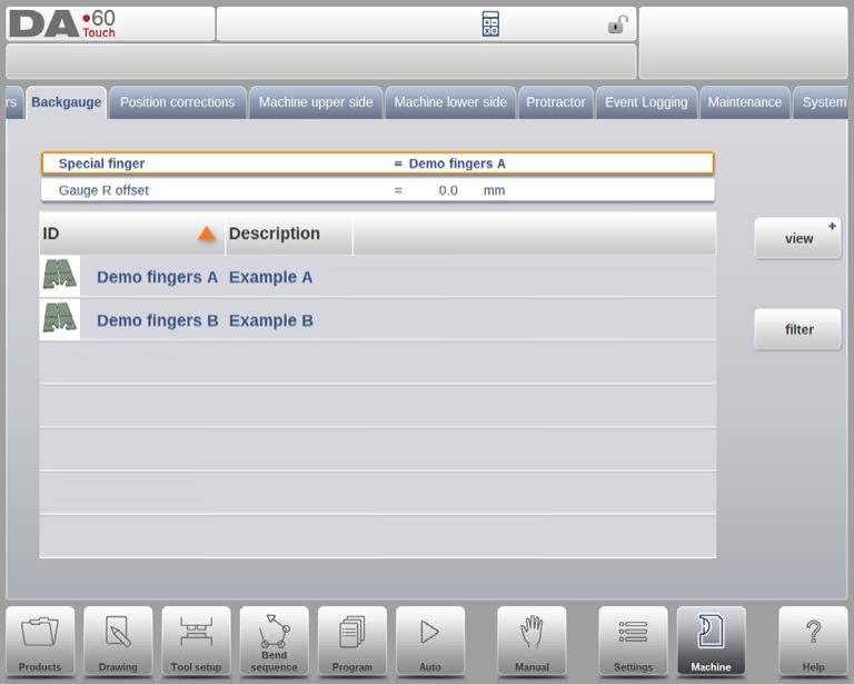
Dito speciale
Ogni set di dita del registro posteriore ha un nome o un ID univoco. Gli utenti possono selezionarli o modificarli dalla libreria delle dita del registro posteriore.
Importazione di nuovi set di dita del registro posteriore
Per importare nuove dita del registro posteriore nella modalità macchina DELEM DA-69T, seguire questi passaggi:
- Fornire un set di dita in formato .ASC con i file necessari.
- Utilizzare la funzione dello strumento di importazione nella pagina Backup/ripristino in modalità Impostazioni per selezionare il set di dita del registro posteriore.
- Programmare la larghezza appropriata e gli offset di sovrapposizione per le dita, assegnando un nome e una descrizione facoltativa.
- Dopo l'importazione, il nome del set di dita appare nella libreria delle dita del registro posteriore.
- Selezionare queste dita per programmare nuovi prodotti e le dita attive possono essere scelte nella parte superiore della schermata Backgauge.
Spostamento X
Se tutti i set di dita vengono eliminati, il sistema riattiva la definizione parametrica del dito. Durante la modifica, è disponibile un parametro aggiuntivo, l'offset X, che indica la differenza di lunghezza tra il dito selezionato e quello utilizzato durante la messa in servizio e la calibrazione della macchina.
Correzioni di posizione
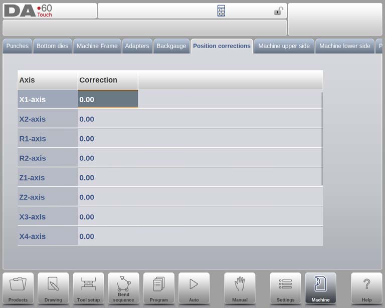
Nella modalità macchina DELEM DA-69T, la correzione delle posizioni degli assi è essenziale quando la posizione meccanica effettiva non corrisponde al valore visualizzato. Questo parametro consente di immettere la differenza calcolata per allineare l'output della macchina con il suo display, garantendo la precisione.
Ad esempio, se il valore programmato e visualizzato è 250 ma la posizione effettiva è 252, si imposterà il parametro di correzione su -2. Viceversa, se la posizione effettiva è 248, la correzione sarà +2.
Queste correzioni di posizione possono essere applicate a tutti gli assi ausiliari, ma sono destinate a un uso temporaneo. Se si verificano discrepanze dopo la messa in servizio o la manutenzione della macchina, utilizzare queste correzioni per riallineare gli assi. In circostanze normali, queste correzioni dovrebbero essere pari a zero, poiché la modalità macchina DELEM DA-69T è configurata per mantenere un posizionamento preciso e accurato durante tutte le sue operazioni.
Esplorazione dei lati superiore e inferiore della macchina
Nell'ottimizzazione della modalità macchina DELEM DA-69T, è fondamentale prestare particolare attenzione alla configurazione dei lati superiore e inferiore della macchina. La geometria della macchina, sia per la trave superiore che per la tavola inferiore, è fondamentale per il rilevamento delle collisioni e la precisione complessiva della macchina.
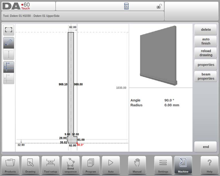
Lato superiore della macchina
Per il lato superiore, la geometria della macchina è programmata come profilo. Questa informazione è essenziale per il rilevamento delle collisioni tra prodotto e macchina. È possibile aggiungere utility o forme speciali per calcoli di collisione precisi. In genere, viene programmata una sola forma.
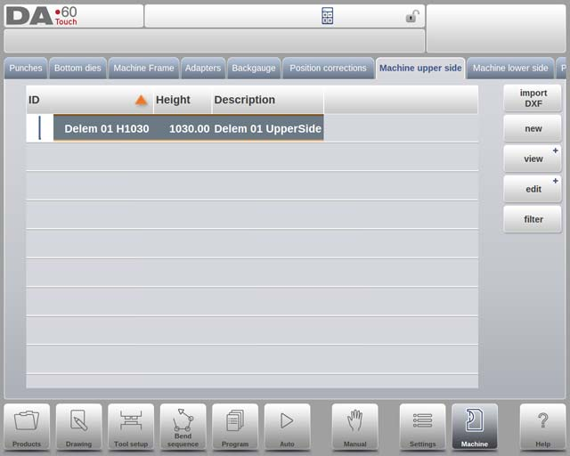
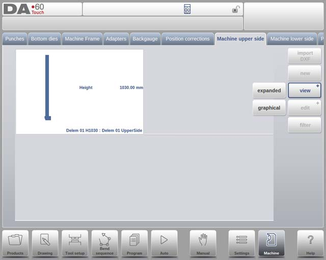
Per visualizzare graficamente le forme della tua macchina, vai alla scheda della libreria, seleziona "Visualizza" e usa "Grafica".
Per aggiungere un nuovo componente della macchina, tocca "Modifica" e poi "Aggiungi", specificando ID, descrizione e altezza del componente. L'altezza viene specificata quando la parte superiore mobile si trova al suo punto morto superiore meccanico.
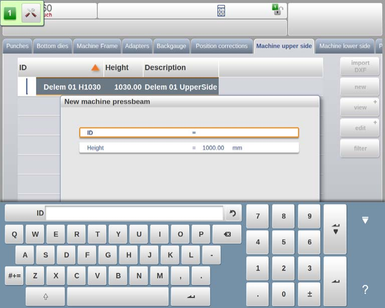
L'editor di disegno consente di abbozzare parti di macchine specificando lunghezze e direzioni dei lati.
Importazione DXF (facoltativa)
Nella modalità macchina DELEM DA-69T, la funzione opzionale di importazione DXF consente di caricare la forma del lato superiore di una macchina. Questa funzionalità è standard nel DA-69T.
Punto di montaggio (facoltativamente programmabile)
Nel disegno della modalità macchina DELEM DA-69T, il punto di montaggio della trave di pressatura è indicato da una freccia triangolare, che mostra il punto in cui il punzone o l'adattatore si collega alla trave di pressatura. I punti di montaggio sono presenti anche nei punzoni e negli adattatori. Se questa funzione non è abilitata, l'indicatore non verrà visualizzato.
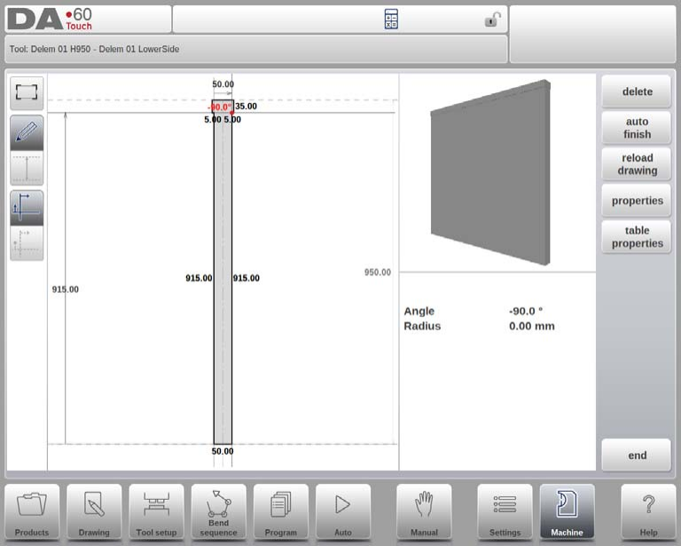
Lato inferiore della macchina
La geometria del lato inferiore è programmata in modo simile, tenendo conto del rilevamento delle collisioni. L'aggiunta di utilità come forme speciali può perfezionare i calcoli delle collisioni. Come per il lato superiore, in genere viene programmata una sola forma.
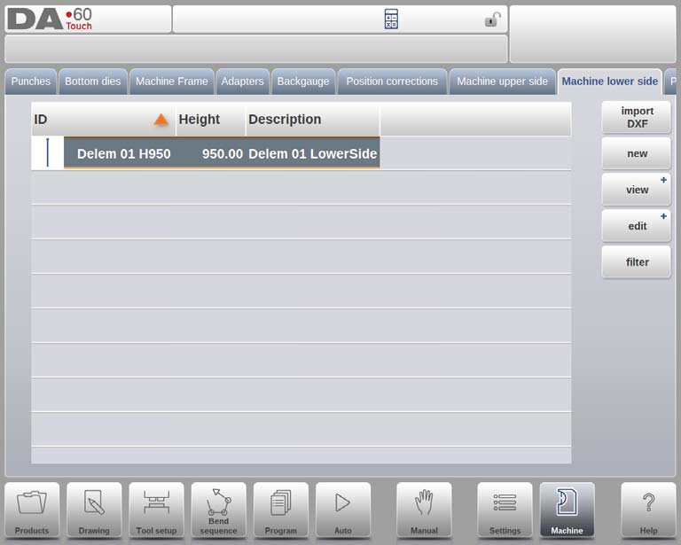
Per aggiungere un componente meccanico, accedi alla scheda Libreria, tocca "Modifica" e usa "Aggiungi" per inserire ID, descrizione e altezza. Per il lato inferiore, l'altezza viene misurata dalla superficie del tavolo al pavimento. L'editor di disegno funziona in modo simile al lato superiore, consentendo schizzi dettagliati del componente.
Importazione DXF (facoltativa)
Nella modalità macchina DELEM DA-69T, la forma del lato inferiore di una macchina può essere importata utilizzando la funzione opzionale di importazione DXF. Questa funzione è standard nel DA-69T e opzionale nel DA-66T.
Punto di montaggio (facoltativamente programmabile)
Il disegno include un punto di montaggio per la tavola, identificato da una freccia triangolare, che indica dove si collegherà la matrice o l'adattatore. Se è presente un asse I, viene visualizzata anche la sua linea di divisione, che mostra il confine tra la parte fissa e quella dinamica della tavola. Per impostazione predefinita, questa linea si trova nella parte superiore della tavola e determina il movimento del portautensile con l'asse I.
Il punto di montaggio definisce la posizione dell'asse I ed è impostato su zero per impostazione predefinita, posizionandolo al centro della macchina (X=0). Questa impostazione può essere regolata per fornire un offset di intervallo dell'asse I. I punti di montaggio sono presenti anche in matrici e adattatori e vengono visualizzati solo se la funzione è abilitata.
Grazie a una configurazione ponderata di questi elementi, la modalità macchina DELEM DA-69T può essere ottimizzata per una maggiore precisione ed efficienza nella lavorazione dei metalli.
Domande frequenti (FAQ)
Come posso mantenere al meglio la precisione del telaio della macchina?
Controlli regolari di allineamento e stabilità, uniti a regolazioni immediate ogni volta che vengono rilevate deviazioni, manterranno la precisione del telaio in modalità macchina DELEM DA-69T.
Qual è un fattore critico nell'ottimizzazione dei lati della macchina?
Per un funzionamento ottimale sono essenziali l'ispezione e la manutenzione regolari dei lati superiore e inferiore, compresa la lubrificazione delle parti mobili e l'ispezione per verificarne l'usura.
Come posso garantire una modifica precisa in modalità macchina DELEM DA-69T?
Utilizzate l'editor di contorni C-frame in modo efficiente e rivedete e regolate regolarmente le impostazioni per adattarle alle specifiche del vostro progetto. Anche la manutenzione e la calibrazione regolari del telaio della macchina contribuiscono alla precisione.
Conclusione
Per ottimizzare la modalità macchina DELEM DA-69T, è fondamentale comprendere il telaio della macchina, utilizzare efficacemente l'editor di contorni a C e gestire l'adattatore. Utilizzare la funzionalità di registro posteriore gestendo la libreria di dita del registro posteriore e ottimizzando le correzioni di posizione. Inoltre, un'analisi approfondita dei lati superiore e inferiore della macchina può migliorare l'efficienza operativa.
Una corretta configurazione e manutenzione sono essenziali per garantire la longevità e le prestazioni della vostra macchina DELEM DA-69T. Seguendo queste linee guida, potrete ridurre al minimo i tempi di fermo e migliorare l'efficienza produttiva. Per un supporto più dettagliato o per qualsiasi domanda, non esitate a contattare il nostro team. Potete anche consultare le nostre risorse e la nostra documentazione aggiuntiva per migliorare ulteriormente le capacità della vostra macchina.


