


Se você busca um conhecimento completo sobre a configuração de punções e matrizes ESA S530, veio ao lugar certo. Neste artigo, abordarei os fundamentos da configuração de punções e matrizes usando o sistema ESA S530, garantindo que você tenha o conhecimento necessário para otimizar seus processos de usinagem.
A configuração do sistema de punção e matriz ESA S530 é crucial para quem busca gerenciar ferramentas com eficiência, a fim de maximizar a produtividade e a precisão em suas operações. Seja você iniciante em fabricação de metais ou um profissional experiente em busca de aprimoramento, este guia fornecerá os insights necessários para configurar e utilizar o sistema ESA S530 com eficiência.
Introdução
No mundo da manufatura industrial, uma configuração eficiente de punção e matriz é fundamental. Ela não só aumenta a produtividade, como também garante que os produtos atendam aos mais altos padrões de qualidade e precisão. ESA S530 A Configuração de Punções e Matrizes foi projetada para otimizar esse processo, fornecendo aos usuários ferramentas robustas para desenhar novas punções e matrizes e utilizar predefinições de forma eficaz. Ao compreender e dominar a configuração do ESA S530, os fabricantes podem reduzir significativamente o tempo de inatividade e melhorar a eficácia geral de suas linhas de produção.
O sistema ESA S530 foi projetado com tecnologia de ponta para oferecer integração perfeita e gerenciamento de ferramentas excepcional. Seus controles intuitivos permitem que os usuários configurem, modifiquem e executem facilmente operações de puncionamento e matriz, garantindo resultados consistentes. A interface foi projetada para facilitar o uso, reduzindo o tempo necessário para treinamento e minimizando erros de configuração.
Como desenhar um novo soco
Siga as instruções a seguir para desenhar um novo punção:
- pressione este botão para exibir a lista de matrizes ou punções

- pressione-o novamente se a lista de dados aparecer.
- Selecione o tipo de punção desejado. A punção pode ser desenhada completamente ou podem ser utilizados os quatro tipos de punção predefinidos com medidas fixas. Variando essas medidas, a punção é redimensionada e redesenhada.
Os seguintes tipos de punção predefinidos estão disponíveis:

É aconselhável utilizar punções predefinidas se o punção necessário for semelhante a um dos tipos propostos (que foram retirados do catálogo), pois será menos difícil de desenhar.
O punção deve ser desenhado completamente se não estiver dentro das categorias de punções predefinidas.
Observação
Na configuração de punção e matriz ESA S530, a precisão do desenho do punção é fundamental para evitar colisões com peças trefiladas. A profundidade de dobra é calculada usando as dimensões do punção. Se for difícil desenhar um punção, use punções predefinidas e ajuste-as com base em dados predefinidos para corresponder à forma real. Essa abordagem garante precisão e eficiência na sua configuração.
- pressione este botão “Configurações” para acessar o menu

- selecione:
- Novo desenho de punção para puxar completamente o soco;
- Novo Tipo 1 para usar um tipo de punção predefinido 1;
- Novo Tipo 2 para usar um tipo de punção predefinido 2;
- Novo Tipo 3 para usar um tipo de punção predefinido 3.
- Novo Tipo 4 para usar um punção predefinido tipo 4 (punção redonda).
- Aparecerá uma janela solicitando a inserção das dimensões do punção:
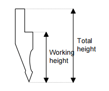
- Insira a altura total e a altura útil, conforme mostrado no desenho.
Acesso à máscara de desenho
Acesse a máscara de desenho após inserir as dimensões do punção e selecionar o tipo de punção. A máscara de desenho muda dependendo do tipo de punção selecionado:
Vá para o [Confirmar] botão e pressione [DIGITAR].
Socos para desenhar
A máscara com os punções a desenhar é criada por meio da função de desenho (consulte o capítulo relativo no manual do operador).
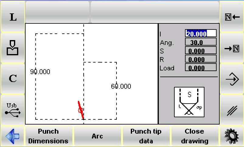
A janela à esquerda é a janela de desenho.
As duas janelas à direita são janelas de entrada de dados de desenho e mudam dependendo da linha desenhada. Elas podem representar:
- Dados do desenho polar;
- Dados do desenho do vértice;
- Os dados de desenho de um arco;
Convenções de desenho
O punção deve ser puxado no sentido anti-horário, lembrando que o localizador fica no lado direito do punção.
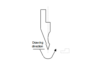
Entrada de vértice
A ponta deve ser definida antes que o desenho do punção possa ser usado. A linha destacada no início do desenho representa um dos dois lados da ponta.
Proceda conforme descrito para definir a ponta:
- Digite o comprimento (l): Comece inserindo o comprimento de um lado da ponta do punção. Pressione [ENTER].
- Digite o ângulo da ponta: Insira o ângulo da ponta para obter um formato preciso. Pressione [ENTER].
- Digite Chanfro (S): Adicione detalhes de chanfro para aumentar a durabilidade. Pressione [ENTER].
- Digite o raio da ponta (R): Especifique o raio para distribuição do impacto. Pressione [ENTER].
- Digite a carga do soco: Indique a capacidade máxima de toneladas por metro. Pressione [ENTER].
A ponta é desenhada e a próxima linha, com o mesmo comprimento daquela usada para a linha 1, é inserida automaticamente.
Como fazer o desenho
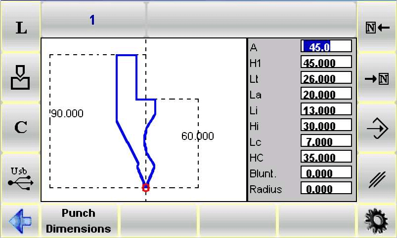
Suponha que o seguinte soco deve ser desenhado:

- Noções básicas de entrada de dados: Comece inserindo os dados da ponta no campo 1 da janela de entrada de dados da ponta do desenho. Em seguida, especifique o comprimento do segundo lado (linha 11) e pressione [DIGITAR].
- Especificando ângulos: O cursor se deslocará para o campo alfa para entrada do ângulo em relação à próxima linha. Insira o ângulo desejado e pressione [DIGITAR]. Isso desenha a próxima linha no modo automático, destacando os dados da linha com um movimento para o campo de entrada de comprimento da linha 1.
- Usando arco para linhas curvas: Para desenhar linhas curvas, pressione [Arco]. Insira o comprimento da linha l2 e a profundidade da linha p1 e pressione [DIGITAR] para prosseguir com a curva. Continue esse processo para as linhas subsequentes, garantindo que os ângulos e comprimentos estejam o mais próximo possível das medidas reais para garantir a precisão.
- Ajustes gráficos: Utilize o utilitário gráfico para ajustar ângulos e comprimentos em ±1° e ±1mm, respectivamente, usando as teclas de seta — direita e esquerda para ajuste de ângulo, para cima e para baixo para ajuste de comprimento.
Como corrigir os dados inseridos
Entradas incorretas podem ser corrigidas quando o sorteio estiver sendo feito.
É possível corrigir estas entradas e navegar entre as diversas linhas desenhadas por meio destas duas teclas, e modificando o valor dos campos;


- use esta tecla para alternar para o campo de entrada anterior e, assim, alternar entre um campo de entrada de linha (1) e um campo de entrada de ângulo (alfa);
- use esta tecla para alternar para a próxima linha e, assim, sempre alternar para o campo de entrada de linha (l);
- usar [DIGITAR] para alternar para o próximo campo de entrada e, assim, alternar entre um campo de entrada de linha (1) e um campo de entrada de ângulo (alfa).
Recuperação de erros
Um erro muito frequente (principalmente se as setas forem usadas para inserir os ângulos) é esquecer de pressionar [DIGITAR] após inserir um ângulo. Isso significa que o comprimento da seção é inserido no campo de entrada do ângulo, criando assim um erro no desenho.
- Use esta tecla para retornar ao campo de entrada do ângulo e inserir o item de dados correto
Como salvar o desenho
- Quando o desenho estiver finalizado, pressione este botão para memorizá-lo

- Digite o nome do soco na janela que aparece.
- Após o nome ter sido inserido, vá para o [Confirmar] botão e pressione [DIGITAR].
Caracteres de nome tolerados
O nome inserido pode ser formado por uma combinação de números e letras (por exemplo, o código do furador no catálogo pode ser usado).
Punções predefinidas
Na fabricação industrial, a configuração de punção e matriz ESA S530 otimiza a produção, oferecendo uma interface clara para o gerenciamento de punções. A máscara de punções predefinida exibe formatos de punção pré-desenhados e dados relevantes.
Navegue por esses dados com as setas ou [DIGITAR] para ver as medidas correspondentes no desenho. Ajuste quaisquer valores e pressione [DIGITAR] para atualizar o desenho.
Para salvar seu trabalho na Configuração de Punção e Matriz do ESA S530, conclua seu desenho e pressione o comando "Salvar". Insira um nome para a punção usando números e letras, como um código de catálogo. Após inserir o nome, selecione a opção [Confirmar] botão e pressione [DIGITAR] para economizar. Este processo garante uma gestão eficiente das ferramentas e fluxos de trabalho de produção otimizados.
Como desenhar um novo dado
Para usar com eficiência a configuração de punção e matriz do ESA S530 para desenhar uma nova matriz, siga estas etapas simplificadas:
- Lista de matrizes de acesso: Pressione o botão para exibir a lista de matrizes; alterne da lista de punções, se necessário.
- Escolha o tipo de matriz: Selecione uma matriz completamente nova ou uma matriz predefinida com medidas fixas. As matrizes predefinidas simplificam o processo quando se assemelham ao que você precisa.
- Desenhar novo dado: Use o desenho completo para matrizes não cobertas por predefinições, especialmente aquelas com múltiplas ranhuras ou formatos exclusivos. Ajuste as matrizes predefinidas se o desenho completo for muito complexo.
- Dimensões de entrada: Pressione o botão de menu, selecione Novo desenho de matriz para design completo ou Novo dado predefinido para predefinições e insira as dimensões da matriz.
- Usar máscara de desenho: Acesse a máscara de desenho após inserir as dimensões; ela será ajustada com base na sua escolha de matriz. Confirme pressionando [DIGITAR].

Estas etapas ajudam você a utilizar de forma eficaz o Configuração de punção e matriz ESA S530 para criação de matrizes precisa e eficiente.
Morrer para ser desenhado
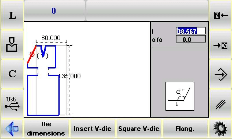
O processo de desenho começa com uma máscara criada por meio da função de desenho.

A janela da esquerda na interface é a sua tela de desenho principal, enquanto as duas janelas do lado direito permitem a entrada de dados específicos para as linhas que estão sendo desenhadas. Estes podem incluir dados polares, de ranhura em V ou de ranhura quadrada. Lembre-se de que o dado normalmente é desenhado no sentido horário, com o localizador no lado direito.
Como Proceder com o Desenho
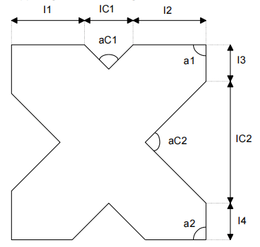
Suponha que o seguinte dado deve ser sorteado:
Para desenhar um novo dado, comece inserindo o comprimento da linha 11 na janela de entrada polar e pressione [DIGITAR]. Em seguida, defina o ângulo referente à linha a seguir. Para entradas de slot, alterne para a janela de entrada de dados do slot e insira o ângulo, a largura, o raio e a carga do slot. Pressione [DIGITAR] para avançar em cada etapa.
Correção de erros
Os erros podem ser corrigidos em tempo real navegando entre os campos de entrada usando as teclas de seta e garantindo que cada entrada seja confirmada com [DIGITAR]. Um erro comum é esquecer de pressionar [DIGITAR] após inserir um ângulo, o que resulta em erros de entrada de dados. Corrija isso retornando ao campo de ângulo e inserindo o valor correto.
Entrando em Slots Quadrados
Para slots quadrados, pressione [Ranhura quadrada] e insira profundidade, largura, raio e carga na janela que aparece. Cada entrada confirmada desenha o slot e retorna à janela de desenho principal para continuar.
Configurações de nivelamento e ranhura pneumática
As ranhuras de achatamento requerem a definição de linhas para o fechamento e o desenho de uma linha de achatamento. Após o perfilamento da matriz, marque-a pressionando [Achatar]. As configurações pneumáticas envolvem uma pequena modificação; após o desenho, ajuste os parâmetros pneumáticos nas dimensões da matriz.
Como salvar o desenho
- Após finalizar o desenho, pressione este botão para memorizá-lo
- Digite o nome do dado na janela que aparece.
- Após o nome ter sido inserido, vá para o [Confirmar] botão e pressione [DIGITAR].
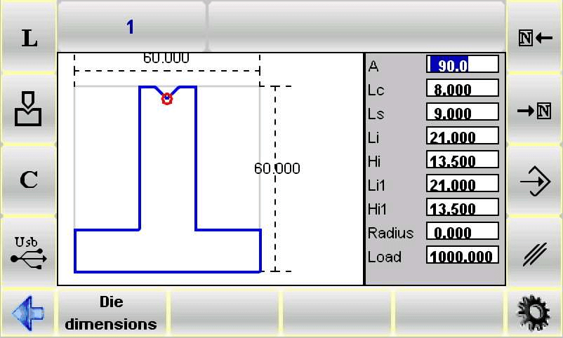
Matrizes predefinidas
O recurso de matrizes predefinidas fornece um formato pré-desenhado e dados relacionados, essenciais para o uso eficiente da configuração de punção e matriz ESA S530.
- Navegando pelos dados:
- Use as setas ou o [DIGITAR] tecla para navegar pelos pontos de dados.
- Cada seleção de dados é vinculada a medições específicas no desenho da matriz, aumentando a precisão.
- Modificando Valores:
- Ajuste qualquer valor conforme necessário e pressione [DIGITAR].
- O desenho é atualizado automaticamente, permitindo modificações rápidas.
- Salvando Desenhos:
- Após finalizar, pressione o botão salvar e digite um nome para o dado.
- Use o [Confirmar] botão e pressione [DIGITAR] para armazenar o desenho com segurança.
Seguindo essas etapas, a configuração do ESA S530 Punch and Die garante operações simplificadas e resultados precisos.
Perguntas Frequentes (FAQ)
Como posso utilizar de forma eficaz a configuração de punção e matriz ESA S530 para minhas operações de prensa dobradeira?
Para aproveitar ao máximo a configuração de punção e matriz da ESA S530, familiarize-se com o recurso de matrizes predefinidas, que permite formatos de matriz pré-desenhados e parâmetros personalizáveis. Isso permitirá ajustes precisos e aumentará a eficiência das suas operações de prensa dobradeira.
Que medidas devo tomar se encontrar um erro ao usar a configuração de punção e matriz do ESA S530?
Primeiro, consulte o manual do usuário para obter códigos de erro específicos para a configuração da matriz e punção ESA S530. A maioria dos problemas pode ser resolvida recalibrando as configurações da matriz ou consultando a seção de solução de problemas para soluções comuns.
Posso salvar várias configurações de matriz com a configuração de punção e matriz do ESA S530?
Com certeza. A configuração de punção e matriz ESA S530 permite salvar e etiquetar diversas configurações de matriz, auxiliando na recuperação e ajuste rápidos para diferentes projetos, otimizando assim seu fluxo de trabalho.
Conclusão
Em resumo, compreender e utilizar a Configuração de Punção e Matriz ESA S530 é crucial para otimizar seus processos de fabricação. As principais etapas incluem navegar pelos dados predefinidos da matriz, modificar valores para ajustes precisos e salvar com eficiência as configurações atualizadas da matriz. Essas etapas garantem que a Configuração de Punção e Matriz ESA S530 continue sendo uma ferramenta essencial para alcançar resultados de produção eficientes e de alta precisão.
A configuração e a manutenção adequadas da punção e matriz ESA S530 são essenciais para maximizar seu desempenho e vida útil. Seguindo os procedimentos descritos e garantindo a manutenção regular, você pode minimizar o tempo de inatividade da máquina e aumentar a eficiência da produção. Para suporte ou dúvidas mais abrangentes, entre em contato com nossa equipe. Além disso, considere explorar nossa outra documentação para ampliar seus conhecimentos sobre como otimizar suas operações com prensa dobradeira.


