


عندما يتعلق الأمر بتعزيز كفاءة إعداد الأدوات في التصنيع، يُعد نظام ESA S860 المتكامل للتصميم بمساعدة الحاسوب (CAD) ثورةً في هذا المجال. إذا كنت تبحث عن طرق لتبسيط عمليات إعداد أدواتك وتتساءل عن كيفية تأثير أنظمة التصميم بمساعدة الحاسوب المتكاملة، فأنت في المكان المناسب.
في هذه المقالة، سأتناول بالتفصيل كيف يُحسّن نظام ESA S860 المدمج في برنامج CAD إجراءات إعداد الأدوات، مُوفرًا الدقة والكفاءة اللازمتين لتطوير عملياتك. سواءً كنتَ مُلِمًّا بأنظمة CAD أو تُستكشف إمكانياتها لأول مرة، سيُقدم لك هذا الدليل رؤىً قيّمة حول كيفية الاستفادة من نظام ESA S860 لتحقيق الأداء الأمثل في مهام الإعداد.
مقدمة
تتميز عناصر التحكم الرقمية Esautomotion في الثنيات، والتي تم تحسينها بواسطة ESA S860 يتيح برنامج CAD المدمج للمستخدمين رسم العناصر الرسومية الرئيسية، مثل أجزاء الآلة، وأداة الثقب، والقالب، وقطعة العمل. تضمن هذه الوظيفة التحقق الدقيق من تسلسلات الانحناء. للحصول على إرشادات حول كيفية الوصول إلى هذه الرسومات، يُرجى مراجعة الدليل الموجز.
وظيفة الرسم
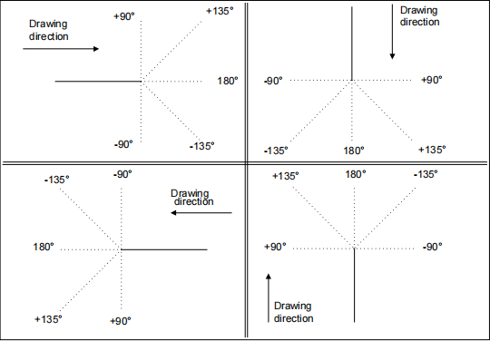
تعمل وظيفة الرسم بتتبع أجزاء الخطوط المستقيمة وفقًا للبيانات التي يُدخلها المُشغِّل. يمكن إدخال البيانات بالتنسيق القطبي أو الديكارتي، مع ذلك، يُنصح باستخدام التنسيق القطبي لتسهيل الإعدادات.
إعداد القطبية لبيانات الرسم
يُبسّط برنامج ESA S860 Integrated CAD عملية تحديد مقاطع الرسم، إذ يتيح لك تحديد البيانات الأساسية، مثل طول المقطع وزاويته بالنسبة للمقطع التالي. تأكد من أن الزوايا تقع ضمن ± 180.0 درجة. عند إدخال الزوايا، التزم بالقواعد المحددة لضمان الدقة.
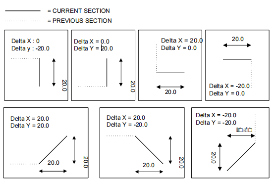
بالنسبة لإعدادات رسم البيانات الديكارتية، يُمكّنك برنامج ESA S860 Integrated CAD من تحديد المقاطع باستخدام إحداثيات تُمثل الفرق بين نقطتي بداية ونهاية المقطع. يُرجى العلم أن هذه الإحداثيات مُرتبطة بنقطة بداية المقطع كما هو موضح في الوثائق المُرفقة.
قبل رسم أي عنصر رسومي، من الضروري إدخال بيانات عامة خاصة بالعنصر المرسوم. يتطلب برنامج ESA S860 Integrated CAD من المستخدمين مراجعة الإرشادات الخاصة بكل عنصر لضمان دقة إدخال هذه التفاصيل.
من خلال الاستفادة من ميزات ESA S860 Integrated CAD، يمكنك تبسيط عملية التصميم الخاصة بك وتحقيق الدقة في رسومات التصنيع الخاصة بك.
قناع الرسم
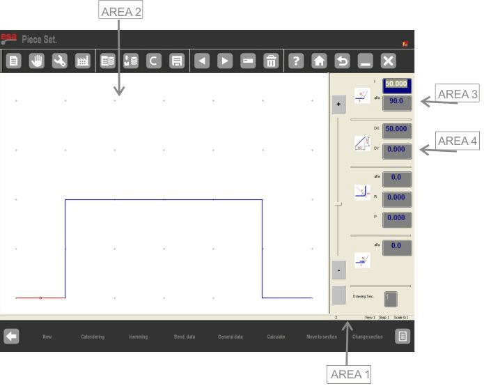
لتنشيط قناع الرسم باستخدام برنامج ESA S860 Integrated CAD، انتقل ببساطة إلى [يتأكد] المفتاح واضغط [يدخل]يتكون قناع الرسم من عدة مناطق رئيسية:
- المنطقة 1: معلومات الرسم
تعرض هذه النافذة تفاصيل أساسية مثل اسم الملف وخطوة الرسم الحالية وعامل المقياس المستخدم. - المجال 2: التتبع الرسومي
هنا، يمكنك عرض الرسم الذي يتوافق مع البيانات التي أدخلتها، مما يسمح بالتصور في الوقت الحقيقي. - المنطقة 3: الإعدادات القطبية
يسمح لك هذا القسم بإدخال طول القسم "ل"والزاوية"ألفا"مقارنة بالقسم التالي، مما يسهل إجراء التعديلات الدقيقة. - المنطقة 4: الإعدادات الديكارتية
أدخل إحداثيات الديكارت "دي اكس" و "دي واي"هنا، والتي تمثل الاختلافات بين إحداثيات القسم الأولي والنهائي.
للحصول على إرشادات حول كيفية استخدام هذه المجالات بفعالية، يوفر دليل ESA S860 Integrated CAD المفصل وصفًا لكيفية ضبط البيانات الخاصة بكل كائن رسومي. سيساعدك استكشاف هذه الوظائف على تحسين مهام الرسم بكفاءة.
إدخال بيانات الرسم
باستخدام برنامج ESA S860 Integrated CAD، يؤدي الوصول إلى الرسم في المنطقة 2 تلقائيًا إلى إنشاء القسم الأول بطول قياسي، مُظلل باللون الأحمر. استخدم مفاتيح الأسهم لتغيير اتجاه الرسم. تأكد من عدم وجود أي قيمة في الحقل "ليتم تأكيد "" في المنطقة 3 عن طريق الضغط على ENTER، وخاصةً في طرازي S860 Touch وS660W.
كيفية إدخال رسم في الوضع القطبي
إدخال رسم في الوضع القطبي باستخدام نظام ESA S860 المتكامل للتصميم بمساعدة الحاسوب (CAD) مُبسَّطٌ لتحقيق الكفاءة. أولًا، إذا لم يكن مؤشر الماوس في الحقل "ل"في المنطقة 3، قم بتنشيط وضع الإعداد القطبي بالضغط على [القائمة التالية] و [تنسيق بولار]بمجرد التنشيط، اتبع الخطوات السهلة التالية لإدخال بيانات الرسم:
- طول المقطع والزاوية:
- أدخل طول المقطع. سيتم تغيير حجم المقطع تلقائيًا، وسينتقل المؤشر إلى "ألفا” حقل لإدخال الزاوية.
- أدخل الزاوية بالنسبة للجزء التالي. سيتحول هذا الجزء إلى اللون الأزرق، وسيُرسم الجزء التالي، الذي سيصبح الجزء الحالي، باللون الأحمر. ستظهر دائرة تشير إلى الجزء الذي سيتم إدخاله.
- دورة إدخال البيانات:
- استمر في إدخال أزواج البيانات الخاصة بالطول والزاوية حتى اكتمال الرسم بالكامل.
- إذا تجاوزت القياسات أبعاد النافذة، فسيتم إعادة قياس الرسم تلقائيًا، وتحديث عامل المقياس في المنطقة 1.
- الانتهاء من الرسم:
- ولإنهاء الأمر، اضبط زاوية القسم الأخير على الصفر.
- اختيار البيانات وتعديلها:
- استخدم مفتاحي و للتنقل بين بيانات الرسم. حدّد الأقسام لعرض أرقام المقاطع الحالية في المنطقة ١.
- لتغيير البيانات، حدد القيمة، وأدخل قيمة جديدة، ثم اضغط على [ENTER] لتحديث الرسم استنادًا إلى المدخلات الجديدة.
- استخدام مفاتيح الاتجاه:
- استخدم الأسهم الاتجاهية والمفاتيح مثل [بيت], [صفحة لأعلى], [PgDn]، و [نهاية] للتنقل بين المقاطع. تتيح هذه المفاتيح أيضًا الحركة قطريًا وتُدخل الزوايا تلقائيًا في "ألفا" مجال.
- حذف الأقسام وإدراجها:
- لحذف مقطع، حدد بيانات المقطع واضغط على مفتاح الحذف. سيتم تعديل المقاطع اللاحقة بناءً على الزوايا السابقة.
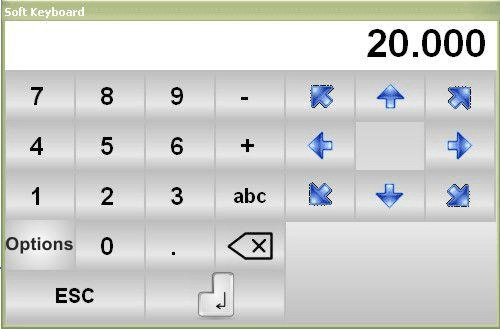
- إدراج أقسام جديدة عن طريق التحديد [أدخل]، مع تمديد الجانب الحالي بمقدار ٢٠ مم. أدخل قيمًا للقطعة الجديدة لتكوين الرسم حسب الحاجة.
استخدام الأسهم الاتجاهية والمفاتيح الموجودة على لوحة المفاتيح التي تعمل باللمس
تتحرك مفاتيح الاتجاه أفقيًا أو رأسيًا عبر المقاطع.
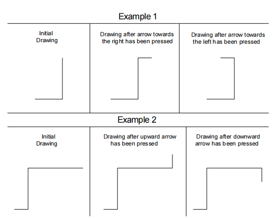
تتحرك مفاتيح الاتجاه بشكل قطري عبر المقاطع.
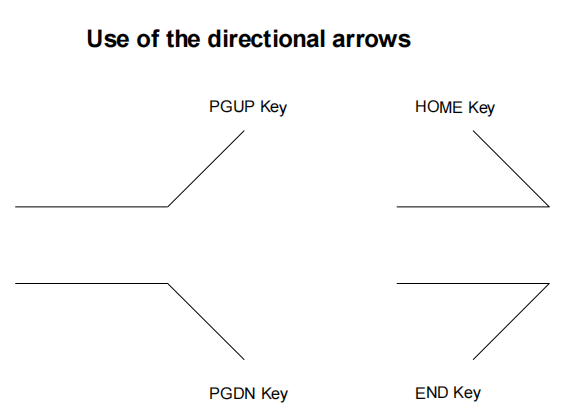
يتم إدخال الزاوية الموجودة تلقائيًا في "ألفاالحقل بين المقطع الحالي والقطعة المتتبعة يعتمد على مفتاح الاتجاه الذي تم الضغط عليه. يجب تأكيد هذه الزاوية باستخدام [يدخل] اضغط على المفتاح إذا كنت تريد الانتقال إلى الأمام وأدخل طول القسم الجديد.
إن تنفيذ هذه الخطوات باستخدام برنامج ESA S860 Integrated CAD يضمن إدخال الرسومات وتعديلها بكفاءة، مما يسمح لك بتعظيم الإنتاجية والدقة في مشاريع CAD الخاصة بك.
كيفية استخدام التنسيق الديكارتي
عندما يتعذر تحديد مقطع بالتنسيق القطبي، يتيح لك نظام ESA S860 Integrated CAD التبديل بسهولة إلى التنسيق الديكارتي. إليك كيفية القيام بذلك:
خطوات التفعيل:
- انتقل إلى قسم الرسم الذي تعمل عليه واضغط على [القائمة التالية] متبوعًا بـ [التنسيق الديكارتي]سيتم نقل المؤشر تلقائيًا إلى المنطقة 4.
- أدخل الفرق بين المحور الأفقي بين نقاط البداية والنهاية في دي اكس مجال.
- أدخل الفرق بين المحور الرأسي في دي واي مجال.
- قم بتأكيد إدخالاتك بالضغط على [يدخل]وسوف يتتبع برنامج ESA S860 Integrated CAD الجزء الجديد لك.
للعودة إلى التنسيق القطبي، اضغط ببساطة على [تنسيق بولار] المفتاح مرة أخرى.
من خلال اتباع الخطوات التالية، يمكنك استخدام تنسيق الديكارت بكفاءة ضمن بيئة ESA S860 Integrated CAD، مما يعزز قدرات التصميم لديك.
الأسئلة الشائعة
هل يمكن لبرنامج ESA S860 Integrated CAD تحسين الدقة في وضع الأدوات؟
نعم، يُحسّن برنامج ESA S860 Integrated CAD الدقة من خلال إتاحة تكوينات وتعديلات دقيقة لمسارات الأدوات ومواضعها. تضمن هذه الدقة توافق إعداداتك تمامًا مع مواصفات التصميم.
ما هي أنواع الملفات المتوافقة مع ESA S860 Integrated CAD؟
يدعم جهاز ESA S860 Integrated CAD مجموعة من تنسيقات الملفات، بما في ذلك ملفات CAD الشائعة مثل DXF وDWG، مما يضمن التوافق مع معظم برامج التصميم ويسهل التكامل بسهولة في سير عملك.
كيف يساهم برنامج ESA S860 Integrated CAD في تسريع دورات الإنتاج؟
من خلال أتمتة جوانب إعداد الأداة وتوفير تصورات تفصيلية لعملية الإعداد، يعمل برنامج ESA S860 Integrated CAD على تقليل المهلة الزمنية بين التصميم والإنتاج، مما يساعد على تسريع دورات الإنتاج الشاملة.
خاتمة
في الختام، يُحسّن نظام التصميم بمساعدة الحاسوب (CAD) المتكامل ESA S860 إعداد الأدوات بشكل ملحوظ من خلال توفير دقة وكفاءة لا مثيل لهما. باستخدام هذا النظام المتكامل، يُمكنك تبسيط عمليات التصنيع، وتقليل وقت الإعداد، وتحسين الإنتاجية الإجمالية. سواءً كان ذلك بفضل التكامل السلس لوظائف التصميم بمساعدة الحاسوب (CAD) أو الإمكانيات المتقدمة التي تُسهّل ترتيب الأدوات بدقة، يُثبت نظام ESA S860 أنه عنصر لا يُقدّر بثمن في قطاع التصنيع الحديث.
للاستفادة الكاملة من برنامج ESA S860 Integrated CAD، نشجعكم على استكشاف المزيد أو التواصل مع فريقنا للحصول على دعم شخصي. لمزيد من المعلومات والإرشادات التفصيلية، تفضلوا بتصفح وثائقنا الشاملة أو تواصلوا معنا مباشرةً. نحن هنا لمساعدتكم في الارتقاء بعمليات التصنيع لديكم إلى مستوى أعلى.


