


في عالم تصنيع المعادن الدقيقة، تُعدّ برمجة أنظمة الثقب والقوالب بفعالية في وضع آلة DELEM DA-69T أمرًا بالغ الأهمية لتحقيق نتائج دقيقة وفعالة. إذا كنت تبحث عن إرشادات حول كيفية برمجة أنظمة الثقب والقوالب في وضع آلة DELEM DA-69T، فأنت في المكان المناسب.
سيرشدك هذا الدليل إلى الخطوات والنصائح الأساسية لإتقان برمجة الثقب والقوالب، المصممة خصيصًا لواجهة DELEM DA-69T. سواء كنت جديدًا على استخدام هذا الوضع الآلي أو تسعى إلى تحسين مهاراتك في البرمجة، فقد صُمم هذا الدليل لمساعدتك على تحقيق الدقة والكفاءة في مشاريعك الخاصة بتشكيل المعادن. دعنا نتعمق في التفاصيل ونساعدك على الاستفادة القصوى من إمكانات وضع آلة DELEM DA-69T.
نظرة عامة على برمجة Punch
في هذه التبويبة، يُمكن برمجة اللكمات المستخدمة في الآلة. يُمكن إضافة لقم جديدة، وتعديل اللكمات الموجودة، وحذفها.
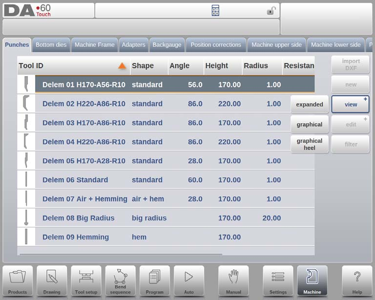
في الصفحة الرئيسية، تظهر قائمة باللكمات المتاحة. باستخدام وظيفة "العرض"، كما هو الحال في وضع "المنتجات"، يمكن اختيار عروض مختلفة. إلى جانب العرض الافتراضي "الموسع"، يتوفر أيضًا "رسومي" و"رسومي" (العرض الرسومي).
الدليل الرسومي
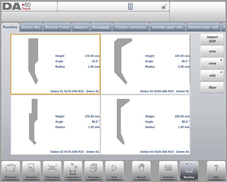
في الرسوم البيانية، يتم عرض هندسة الأدوات بالإضافة إلى الخصائص الرئيسية.
دليل رسومي يثقب بالكعب
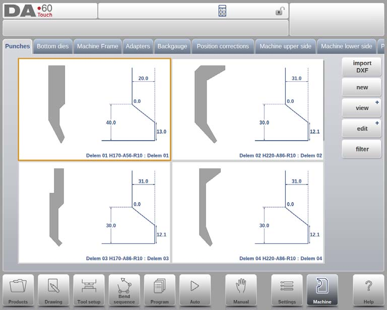
في الكعب الرسومي، يتم عرض هندسة الأدوات بالإضافة إلى خصائص الكعب.
إنشاء لكمة جديدة
الخطوة 1: إنشاء لكمة جديدة
لإنشاء مثقاب جديد، ابدأ بالنقر على "جديد" في المكتبة. سيؤدي هذا إلى بدء عملية تحديد ملف تعريف المثقاب باستخدام إمكانيات البرمجة والرسم في وضع الآلة DELEM DA-69T.

الخطوة 2: برمجة الشكل الأساسي والمعرف
- شكلاختر الشكل الأساسي للثقب الذي يتوافق مع الإجراء المطلوب. الخيارات المتاحة تشمل:
- لكمة قياسية:تستخدم لثني الهواء والقاع الأساسي.
- لكمة ثني الحافة:يتميز بقاعدة مسطحة لتناسب انحناءات الحافة المحددة.
- لكمة ثني الحافة الهوائية:مناسب لثنيات الهواء العادية ووظائف الحاشية.
- لكمة نصف قطرية كبيرة:مصممة للانحناءات ذات نصف القطر الكبير.
- بطاقة تعريفعيّن اسمًا أو رقمًا فريدًا، لا يتجاوز ٢٥ حرفًا، لتعريف الأداة. يمكن أن يشمل ذلك أحرفًا أبجدية رقمية. بعد الانتهاء، انقر على "قبول" للانتقال إلى معلمات بيانات الأداة.
الخطوة 3: تحديد معلمات بيانات الأداة
بعد إكمال الشكل والمعرف، ستظهر نافذة منبثقة في وضع آلة DELEM DA-69T تطلب منك إدخال الأبعاد الأولية وخصائص الأداة. تختلف المعلمات المحددة بناءً على شكل الثقب المحدد مسبقًا.
الخطوة 4: استيراد DXF اختياريًا
لمزيد من الراحة، يمكن أيضًا استيراد شكل المثقب باستخدام وظيفة استيراد DXF الاختيارية. هذه الميزة قياسية في وضع آلة DELEM DA-69T، مما يوفر طريقة فعّالة لدمج التصاميم المعقدة.
لكمة قياسية

- ارتفاع: ضروري لحساب عمق الانحناء. أدخل البيانات بدقة.
- زاوية:اضبط زاوية طرف اللكمة لتتناسب مع احتياجات الانحناء.
- نصف القطر:يجب أن يكون نصف قطر طرف اللكمة أكبر من نصف قطر الانحناء الناتج.
- عرض:حدد عرض الأداة للحصول على برمجة دقيقة.
- مقاومة:تحديد الحد الأقصى لقوة الأداة.
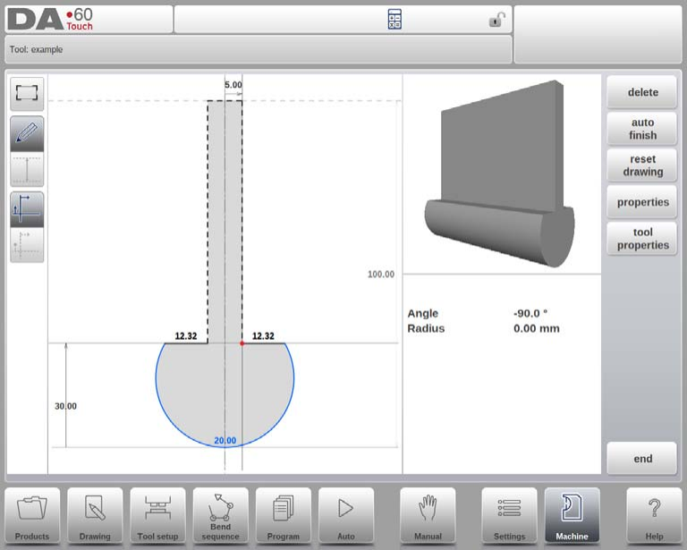
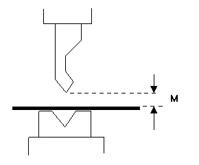
رسم اتجاه اللكمة على الشاشة
الجانب الأيمن للأداة هو جانب القياس الخلفي. ستُوضع النقطة السفلية للثقب على الخط المركزي لشكل مكبس الثني.
رسم وتكوين اللكمة
- رسماستخدم الزوايا وأطوال الخطوط لرسم الأدوات. استخدم أدوات اللمس كما هو الحال في رسم المنتجات.
- نقطة التثبيت (قابلة للبرمجة اختياريًا): يشير إلى نقطة الاتصال على شعاع الضغط، المتوفرة في التكوينات العادية والمدورة.
وظائف الرسم
- حذف السطر:إزالة الأجزاء غير المرغوب فيها.
- الانتهاء التلقائي:إكمال مخطط الأداة تلقائيًا.
- إعادة تعيين/إعادة تحميل الرسم:العودة إلى الشكل الأساسي للكمات الجديدة أو الموجودة.
- ملكيات:تعديل سمات الخط وتعيين أسطح الحاشية.
- خصائص الأداة:تحديث بيانات الأداة والأوصاف.

المعلمات الإضافية
- وصف:اسم أداة مختصر وقابل للتعديل.
- مقاومة:يحدد الحد الأقصى للقوة المسموح بها.
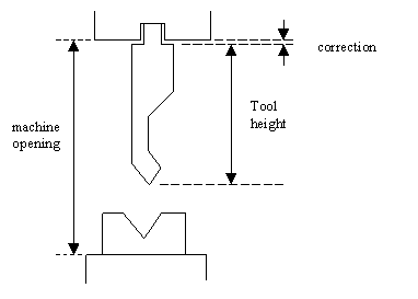
- نوع الدعم:اختر "الرأس" أو "الكتف" المثبت للحصول على دقة المحور Y. 0 = مثبت على الكتف (الإعداد الافتراضي)، 1 = مثبت على الرأس.
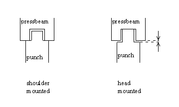
عند اختيار "مثبت على الكتف"، يُحسب موضع المحور الصادي بناءً على ارتفاع الأداة القياسي. هذا هو الإعداد الافتراضي. عند اختيار "مثبت على الرأس"، يُجرى تصحيح لحساب المحور الصادي.
4. مفضل:قم بتحديد الأدوات للاختيار المفضل في العمليات الآلية.
5. المحول الافتراضي:ضبط المحولات المستخدمة بشكل شائع للتحميل التلقائي.
6. أبعاد الكعب:قم بتحديد عرض الكعب وارتفاعه ونصف قطره دون التأثير على الارتفاع الإجمالي للأداة.
تحرير رسومات اللكمة
اختر أدوات المكتبة وحرّرها باستخدام أدوات الرسم المتاحة. تظهر الأداة على الشاشة، ويمكنك تعديلها باستخدام أدوات الرسم.
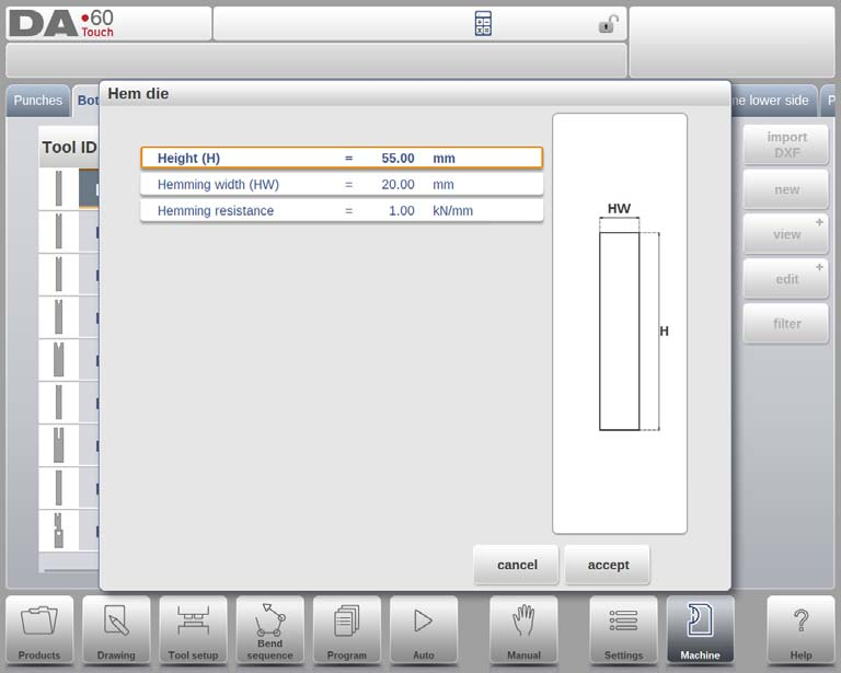
لكمة ثني الحافة

للحصول على برمجة فعالة في وضع آلة DELEM DA-69T، قم بتكوين معلمات ثقب ثني الحافة بدقة على النحو التالي:
1. ارتفاع:أدخل الارتفاع الإجمالي للأداة بدقة، فهو أمر ضروري لحساب عمق الانحناء.
2. عرض الحاشية:أدخل عرض الأداة لتحديد منطقة التلامس مع المادة.
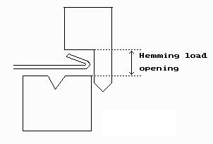
3. فتح حمولة الحاشية:قم ببرمجة موضع فتح المثقب، مع الأخذ في الاعتبار مضاعفة سمك الورقة للحصول على وضع الحاشية الصحيح.
4. مقاومة الهيمنج:قم بضبط الحد الأقصى للقوة التي يمكن للأداة أن تتحملها أثناء عملية الحاشية لحماية سلامة الأداة.
بعد إدخال هذه القيم، قم بإنشاء رسم الأداة من خلال تحديد الزاوية وطول الخط، باستخدام أدوات الرسم باللمس إذا لزم الأمر، على غرار أساليب تصميم المنتج.
لكمة ثني الحاشية بالهواء +
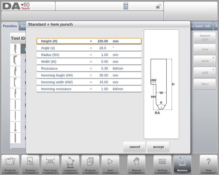
- ارتفاع:أدخل ارتفاع الأداة الإجمالي لتحديد عمق الانحناء بدقة.
- زاوية:اضبط زاوية طرف اللكمة للحصول على نتائج الانحناء المطلوبة.
- نصف القطر:استخدم نصف قطر طرف اللكمة كنصف قطر داخلي للانحناء إذا كان أكبر من نصف القطر الداخلي المحسوب.
- عرض:قم بتحديد عرض الأداة للحصول على محاذاة صحيحة.
- مقاومة:قم بتحديد الحد الأقصى للقوة المسموح بها على الأداة للاستخدام الآمن.
- ارتفاع الحاشية:اضبط ارتفاع اللكمة لحركتها لأسفل أثناء عملية الحاشية.
- عرض الحاشية:أدخل عرض جزء اللكمة للاتصال بالمنتج.
- مقاومة الهيمنج:حدد الحد الأقصى للقوة التي تستخدمها الأداة أثناء عملية الحاشية لمنع التحميل الزائد.
- فتح حمولة الحاشية:قم ببرمجة موضع فتح المثقب، مع الأخذ في الاعتبار إدخال المنتج وسمك الورقة.
إنشاء رسومات الأدوات
استخدم أدوات الرسم في جهاز DELEM DA-69T لإنشاء ملفات تعريف الأدوات. أدخل قيم الزوايا وأطوال الخطوط الأساسية، مستخدمًا أدوات الرسم باللمس عند الحاجة. تتوفر أدوات الرسم باللمس أيضًا كما هو الحال مع طريقة رسم المنتج.

لكمة نصف قطرية كبيرة
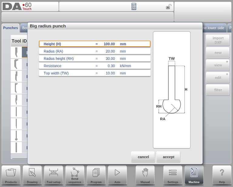
- ارتفاع:أدخل الارتفاع الإجمالي للأداة لحساب عمق الانحناء الصحيح.
- نصف القطر:حدد نصف قطر طرف اللكمة لإجراء عمليات ثني دقيقة.
- ارتفاع نصف القطر:يشير إلى ارتفاع جزء نصف القطر الكبير للأداة، كما هو موضح في رسم الماكينة.
- مقاومة:قم بضبط الحد الأقصى للقوة المسموح بها على الأداة لمنع التحميل الزائد.
- العرض العلوي:قم بتحديد العرض في الجانب العلوي للثقب للحصول على ملاءمة مناسبة للأداة.
بعد إدخال هذه القيم، استخدم أدوات الرسم في الجهاز لإنشاء ملف تعريف للأداة بإدخال قيم الزاوية وطول الخط. تتوفر أدوات الرسم باللمس، وهي مشابهة لطرق رسم المنتجات.
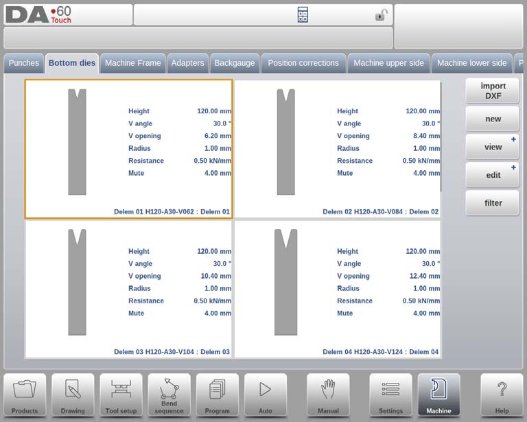
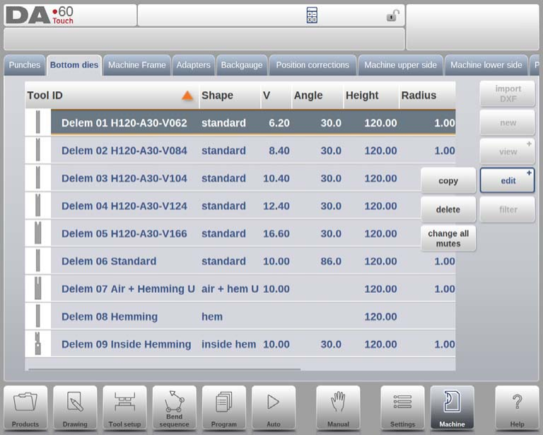
برمجة القوالب السفلية
في هذه التبويبة، يُمكن برمجة القوالب السفلية المُستخدمة في الآلة. يُمكن إضافة قوالب جديدة، وتعديل القوالب الموجودة، وحذفها.

في الصفحة الرئيسية، تظهر قائمة القوالب المتاحة. باستخدام وظيفة "عرض"، كما هو الحال في وضع "المنتجات"، يمكنك اختيار طرق عرض مختلفة. إلى جانب العرض الافتراضي "موسع"، يتوفر أيضًا "رسومي".
الدليل الرسومي
في الرسوم البيانية، يتم عرض هندسة الأدوات بالإضافة إلى الخصائص الرئيسية.
لبرمجة قالب جديد، انقر فوق تحرير في المكتبة ثم استخدم جديد.
إنشاء قالب جديد
الخطوة 1: إنشاء قالب جديد
لإنشاء قالب جديد، ابدأ بالنقر على "أخبار" في مكتبة القوالب. يُفعّل هذا الإجراء عملية تحديد ملف تعريف القالب باستخدام إمكانيات البرمجة والرسم في وضع الآلة DELEM DA-69T.
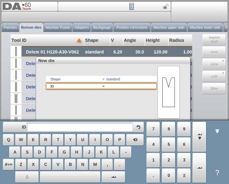
الخطوة 2: برمجة الشكل الأساسي والمعرف
شكلاختر الشكل الأساسي للقالب الذي يتوافق مع الإجراء المطلوب. تشمل الخيارات المتاحة في وضع آلة DELEM DA-69T ما يلي:
- قالب قياسي:تستخدم لثني الهواء والقاع الأساسي.
- قالب ثني الحافة:يأتي مع جزء علوي مسطح لثنيات الحافة المحددة.
- قالب ثني الحافة الداخلية:مناسب لثنيات الهواء ووظائف الحاشية.
- ثني الحافة + الهواء:مصممة لثنيات الهواء مع وظائف حاشية محددة.
- قالب متعدد V:يتميز بفتحات متعددة على شكل V و/أو U.
- قالب Vario-V:يوفر فتحات متغيرة V أو U (متوفرة إذا كان نظام Vario-V موجودًا).
- قالب ثني الحافة الداخلية متعدد الأشكال:يتضمن فتحات متعددة على شكل V أو U مع نظام حاشية متكامل.
- قالب ثني حافة إطار الباب:قالب على شكل حرف V مدمج مع ميزة حاشية داخلية منفصلة لإنتاج إطار الباب.
- قالب انحناء الجناح:يتضمن أجزاء نصف قطرية دوارة لتطبيقات خاصة.
بطاقة تعريفعيّن اسمًا أو رقمًا فريدًا لتعريف الأداة، لا يتجاوز ٢٥ حرفًا. يمكن أن يتضمن هذا المعرف أحرفًا أبجدية رقمية. بعد الانتهاء، انقر على "قبول" للانتقال إلى معلمات بيانات الأداة.
الخطوة 3: تحديد معلمات بيانات الأداة
بعد إكمال الشكل والمعرف، سيعرض وضع آلة DELEM DA-69T نافذة منبثقة تطلب منك إدخال الأبعاد الأولية وخصائص الأداة. تختلف المعلمات المحددة بناءً على شكل القالب المختار.
الخطوة 4: استيراد DXF (خياري)
لمزيد من الراحة في وضع آلة DELEM DA-69T، يمكن أيضًا استيراد شكل القالب باستخدام وظيفة استيراد DXF الاختيارية. هذه الميزة قياسية، وتوفر طريقة فعّالة لدمج التصاميم المعقدة.
قالب قياسي

- عرض:هذا هو عرض الأداة التي سيتم برمجتها في وضع الماكينة DELEM DA-69T.
- ارتفاع:يحدد الارتفاع الإجمالي للأداة، وهو أمر ضروري لحساب عمق الانحناء بدقة.
- نصف القطر: يشير إلى نصف قطر الحواف عند فتحة V للقالب.
- زاوية V: يشير إلى زاوية القالب التي ستؤثر على عملية الانحناء.
- افتتاح V:البعد الفعلي لفتحة V، حيث أن العرض V هو المسافة بين الخطوط الملامسة المتقاطعة.
- خيارات القاع V:
- معيار:زاوية حادة في الأسفل.
- دائري:القالب السفلي بنصف قطر يتم ضبطه بواسطة "نصف القطر الداخلي".
- مستوي:قاع مسطح ذو أبعاد محددة عبر "عرض القاع".
- مقاومة:القوة القصوى المسموح بها على الأداة.
اتجاه الرسم و نقطة التثبيت (قابلة للبرمجة اختياريًا)
في وضع الماكينة DELEM DA-69T، يكون الجانب الأيمن للقالب مُحاذيًا للمقياس الخلفي. يُحاذي منتصف فتحة الشكل V مركز شكل مكبس الثني. عند إدخال الأبعاد القياسية، تُرسم الأدوات باستخدام قيم الزاوية وطول الخط، مع توفر أدوات رسم اختيارية.

تشير نقطة تثبيت القالب، المُشار إليها بسهم مثلث في الرسم، إلى مكان اتصال القالب بالطاولة أو المحول. تتوفر نقاط تثبيت منفصلة للاتجاهين العادي والمُحوَّر. تتوفر هذه الميزة في كلٍّ من المحولات والطاولة. في حال عدم تفعيلها، لن تظهر المؤشرات.
وظائف الرسم
أثناء الرسم، تتوفر وظائف مختلفة:
- حذف السطر:يزيل جزءًا من الخط من الرسم.
- تغيير الارتفاع:ضبط قياس ارتفاع الأداة.
- الانتهاء التلقائي:يكمل مخطط الأداة تلقائيًا.
- إعادة تعيين الرسم:إعادة التعيين إلى شكل الأداة الأولي للقالب الجديد.
- إعادة تحميل الرسم:العودة إلى الشكل الأساسي للقوالب الموجودة.
خصائص الأداة

يمكن تعديل خصائص الأداة لـ:
- ملكيات:تعديل تفاصيل الخط أو الزاوية، وإضافة/إزالة نصف القطر، وتعيين أسطح الحاشية.
- وصف الأداة:قم بتعيين أو تحرير اسم وصفي في حدود 25 حرفًا.
- مقاومة:ضبط الحد الأقصى لقوة الأداة.
- صامت:قم بتحديد مسافة كتم الصوت لتغييرات السرعة.
- مفضل:تعيين الأدوات المفضلة للاختيار التلقائي.
- المحول الافتراضي:تعيين المحولات الافتراضية لمجموعات محولات الأدوات الشائعة.
تحرير رسم القالب
لتعديل أداة موجودة في وضع آلة DELEM DA-69T، حدد الأداة من المكتبة واستخدم مرافق الرسم لإجراء التغييرات.
قالب ثني الحافة
- ارتفاع:هذا هو الارتفاع الإجمالي للأداة وهو أمر بالغ الأهمية لحسابات عمق الانحناء.
- عرض الحاشية:عرض الأداة التي تحتاج إلى البرمجة.
- مقاومة الهيمنج:القوة القصوى المسموح بها على الأداة أثناء عملية الحاشية لمنع التلف.
بعد إدخال هذه القيم، يمكنك إنشاء رسم الأداة باستخدام أدوات الرسم في جهاز DELEM DA-69T. يتضمن ذلك إدخال الزوايا وأطوال الخطوط، مع توفر أدوات الرسم باللمس للمساعدة في هذه العملية.

قالب ثني الحافة الداخلية
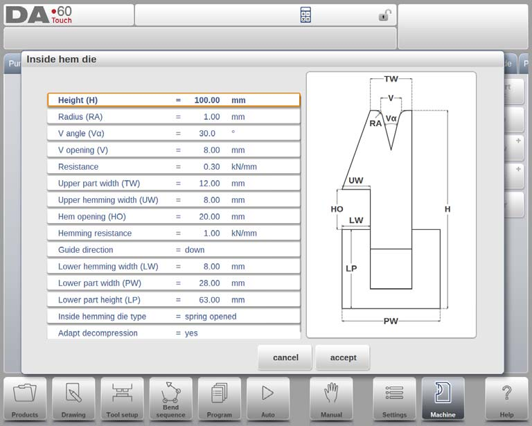
- ارتفاع:يمثل الارتفاع الإجمالي للأداة، وهو أمر بالغ الأهمية لحساب عمق الانحناء.
- نصف القطر:يحدد نصف قطر حواف فتحة V.
- زاوية V:يحدد زاوية القالب.
- افتتاح V: يشير إلى حجم فتحة V.
- أسفل على شكل حرف V:خيارات الجزء السفلي داخل فتحة V:
- 'المعيار': زاوية حادة في الأسفل.
- 'دائري': الجزء السفلي من القالب بنصف قطر قابل للتعديل بنصف القطر الداخلي.
- 'مسطح': يتم تعديل الجزء السفلي المسطح من خلال 'عرض الجزء السفلي'.
- مقاومة:القوة القصوى المسموح بها على الأداة.
- عرض الجزء العلوي:عرض الجزء العلوي من القالب.
- عرض الحاشية العلوية:العرض المستخدم لعملية الحاشية في الجزء العلوي.
- فتحة الحاشية:ارتفاع القالب عند فتحه لوضع المنتج.
- مقاومة الهيمنج:أقصى قوة أثناء عملية الحاشية.
- دليل الاتجاه:يحدد البناء الميكانيكي.
- عرض الحاشية السفلي:عرض قطعة الحاشية في الجزء السفلي.
- عرض الجزء السفلي:عرض الجزء السفلي.
- ارتفاع الجزء السفلي:ارتفاع الجزء السفلي.
15. أنواع قوالب الحاشية الداخلية:
- الربيع مفتوح:
- الوضع الأولي هو للأعلى بسبب زنبرك داخلي.
- الانحناء المسبق:يتم وضع الورقة أعلى القالب المفتوح.
- ثني الحافة:يتم وضع المنتج المثني مسبقًا في فتحة الحافة؛ مع الأخذ في الاعتبار سمك الورقة لحساب العمق.
- مفتوح ومغلق:
- يتم قفله في وضع مرتفع بشكل افتراضي، مما يتطلب آلية لفتحه من أجل الحاشية.
- مغلق عادة:
- يبدأ في وضع منخفض ويتطلب التنشيط لإجراء الحاشية.
16. تكييف الضغط
- خيارات:
- "لا": لا تتم إضافة قيمة الافتتاح.
- "نعم": تمت إضافته لكل من انحناءات الهواء وانحناءات الحاشية.
- "انحناءة الهواء": تمت إضافتها حصريًا لانحناءات الهواء.
رسم الأدوات واستيراد DXF (خياري)

بعد إدخال القيم، يمكنك إنشاء رسومات الأدوات باستخدام مدخلات الزاوية وطول الخط، أو اختيار وظيفة استيراد DXF. تأكد من وضع جسم القالب على الطبقة 0، والأجزاء المتحركة على طبقة أخرى تُسمى "الحاشية الداخلية" لاختيار نوع الأداة تلقائيًا.
الهواء + ثني الحافة على شكل حرف U
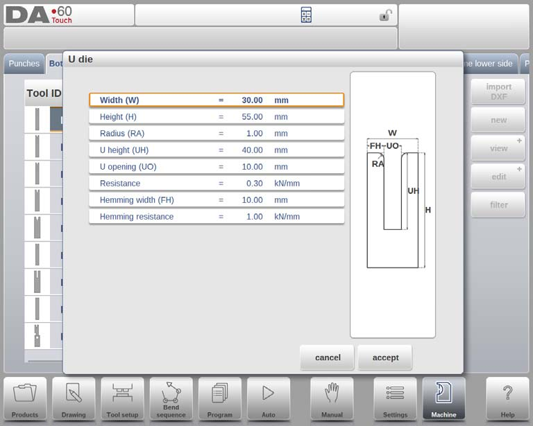
- عرض:قم بقياس وإدخال عرض الأداة.
- ارتفاع:أدخل الارتفاع الإجمالي، وهو أمر حيوي لحساب عمق الانحناء.
- نصف القطر:قم بتحديد نصف قطر حواف الفتح على شكل حرف U للحصول على انحناءات ناعمة.
- ارتفاع حرف U:حدد ارتفاع فتحة الحرف U لتحديد عمق الانحناء.
- افتتاح U:أدخل عرض الفتحة على شكل حرف U لتتناسب مع متطلبات المواد.
- مقاومة:ضبط الحد الأقصى للقوة المسموح بها على الأداة.
- عرض الحاشية:قم بقياس عرض الجزء الأمامي لدعم الحاشية.
- مقاومة الهيمنج:تحديد حد القوة أثناء عملية الحاشية.
بعد إدخال هذه القيم، استخدم أدوات الرسم لإنشاء ملف تعريف للأداة بتحديد الزوايا وأطوال الخطوط. كما يتميز وضع الآلة في جهاز DELEM DA-69T بأدوات رسم باللمس للمساعدة في تصميم ملفات تعريف دقيقة.

قالب متعدد V
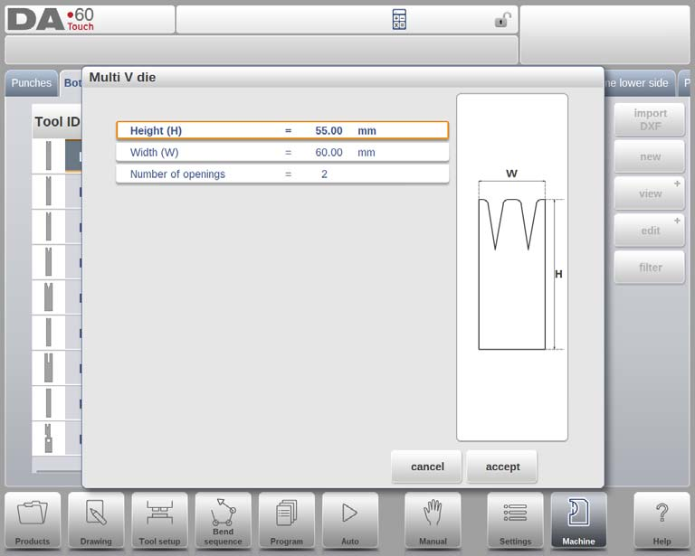
- ارتفاع:أدخل الارتفاع الإجمالي للأداة، حيث أنه أمر بالغ الأهمية لحساب عمق الانحناء بدقة في وضع الماكينة DELEM DA-69T.
- عرض:حدد عرض الأداة لضمان المحاذاة الصحيحة وتطبيق القوة أثناء عمليات الانحناء.
- عدد الفتحات:أدخل عدد فتحات V أو U الموجودة على الأداة لإعداد الماكينة بدقة.
خصائص فتح U / V
- خصائص الافتتاح:قم ببرمجة الخصائص المحددة لكل فتحة V أو U في قسم "الخصائص" في واجهة وضع الماكينة DELEM DA-69T.
- مقاومة الأداة:اختر ما إذا كنت تريد برمجة مقاومة الأداة بشكل عام أو بشكل خاص لكل فتحة لتحقيق التحكم الدقيق أثناء عملية الانحناء.

1. افتتاح U/V:اختر بين فتحات U أو V، والتي ستحدد نوع الانحناء الذي ستقوم ماكينة DELEM DA-69T بتنفيذه.
2. نصف القطر:اضبط نصف قطر حواف فتحة V للتأثير على زاوية الانحناء وتدفق المواد.
3. زاوية V:برمج زاوية القالب لتحقيق دقة الانحناء والحدة المطلوبة.
4. افتتاح V:أدخل حجم فتحة V لتتناسب مع سمك المادة واحتياجات الانحناء.
5. أسفل على شكل حرف V:اختر من:
- معيار:زاوية سفلية حادة.
- دائري:أسفل مع "نصف القطر الداخلي" المحدد.
- مستوي:الجزء السفلي مع "عرض الجزء السفلي" المحدد.
6. المقاومة:حدد أقصى قوة مسموح بها لكل فتحة V أو U. استخدم قيمة افتراضية، إن وجدت، لجميع الأدوات.
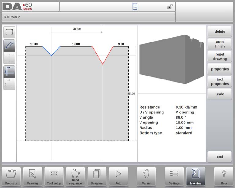
رسم الأدوات
أدخل الزوايا وأطوال الخطوط باستخدام أدوات الرسم في وضع الآلة DELEM DA-69T لإنشاء ملفات تعريف دقيقة للأدوات. كما تتوفر أدوات الرسم باللمس، كما هو الحال في طريقة رسم المنتج.
قالب Vario V (متاح فقط في حالة وجود نظام Vario-V)

- فتح U / V: اختر بناءً على احتياجاتك في الانحناء باستخدام نظام Vario-V.
- ارتفاع: أدخل ارتفاع الأداة الإجمالي الضروري لحساب عمق الانحناء.
- عرض القالب وزاوية V: قم بإدخال نصف العرض ونصف الزاوية لإعداد الأداة بدقة.
- نصف القطر: قم بتحديد نصف قطر حواف الفتحة.
- ارتفاع وعرض القاع: حدد الأبعاد للحصول على تكوين دقيق للقالب.
بعد إدخال هذه القيم النموذجية، يمكنك إنشاء رسم الأداة باستخدام مرافق الرسم.

خصائص الأداة
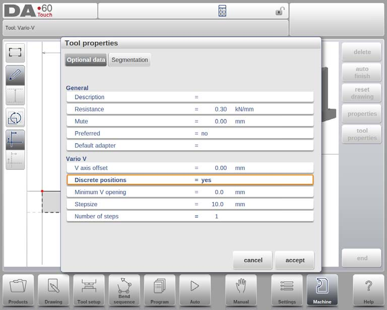
- وصف: قم بتسمية الأداة بشكل مختصر لتحديد المكتبة.
- المقاومة والكتم: تعيين حدود القوة القصوى ومسافة الكتم فوق الورقة.
- إزاحة المحور V والمواضع المنفصلة: إدارة وضعية الفتح على شكل V والفواصل الزمنية.
- الحد الأدنى لفتحة V، حجم الخطوة، عدد الخطوات: قم بتحديد معلمات الافتتاح للمواضع المنفصلة.
استيراد DXF (اختياري)
استخدم وظيفة استيراد DXF مع جسم القالب السفلي على الطبقة 0. تأكد من وجود الأجزاء المتحركة على طبقة منفصلة تسمى "vario V" للتعرف التلقائي.
قالب متعدد الأشكال على الحافة الداخلية

- الارتفاع (H): الارتفاع الإجمالي للأداة لحساب عمق الانحناء.
- عرض الجزء العلوي (TW): عرض القسم العلوي من القالب.
- عدد الفتحات: فتحات V أو U في الأداة.
- زاوية الحافة (ها): زاوية وحدة الحاشية.
- عرض الحاشية العلوية (UW): عرض القطعة للحاشية في الجزء العلوي.
- فتحة الحاشية (HO): ارتفاع القالب عند فتحه لوضع ثنيات الحافة.
- مقاومة الحاشية: أقصى قوة أثناء عملية الحاشية.
- عرض الحاشية السفلية (LW): عرض القطعة للحاشية في الجزء السفلي.
- عرض الجزء السفلي (PW) والارتفاع (LP): أبعاد القسم السفلي من القالب.
- أنواع قوالب الحاشية الداخلية
- الربيع مفتوح: يستخدم زنبركًا لعمليات الثني المسبق وثني الحاشية.
- مفتوح ومغلق: وضع قفل مرتفع للثني القياسي؛ وفتح للخياطة.
- مغلق عادة: الوضع مغلق، يتطلب التنشيط للخياطة.
- تكييف الضغط: خيارات لإضافة قيمة فتح الحاشية إلى فك الضغط. الخيارات هي: "لا" (غير مُضافة)، "نعم" (مُضافة لكلٍّ من ثنيات الهواء والحاشية)، أو "ثني الهواء" (مُضافة لثنيات الهواء فقط).
خصائص فتح U / V
حدّد خصائص الأداة لكل فتحة V أو U ضمن "الخصائص". يمكن ضبط مقاومة الأداة بشكل عام أو خاص.
- فتح U / V:نوع الفتحة.
- نصف القطر:نصف قطر حافة فتحة V.
- زاوية V:زاوية القالب.
- افتتاح V:حجم فتحة على شكل V.
- أسفل على شكل حرف V:
- 'المعيار': زاوية حادة.
- 'دائري': أسفل بنصف قطر قابل للبرمجة (نصف القطر الداخلي)
- 'مسطح': قاع مسطح مع بُعد محدد ('عرض القاع').
- مقاومة:الحد الأقصى للقوة لهذه الفتحة؛ إذا كانت موحدة، اتركها فارغة لأن خصائص الأداة كافية.

بعد إدخال القيم، أنشئ رسومات الأدوات باستخدام الزوايا وأطوال الخطوط، باستخدام أدوات الرسم باللمس واستيراد DXF الاختياري. يدعم جهاز DA-69T هذه الميزة تلقائيًا، بينما هي اختيارية في جهاز DA-66T. في DXF، يجب أن تكون الأشكال في الطبقة 0 والجزء المتحرك في طبقة منفصلة. إذا كان الاسم "inside hem"، فسيحدد المستورد نوع الأداة تلقائيًا؛ وإلا، يلزم التحديد اليدوي. يجب أن يكون كلا جزئي DXF منحنيين مغلقين.
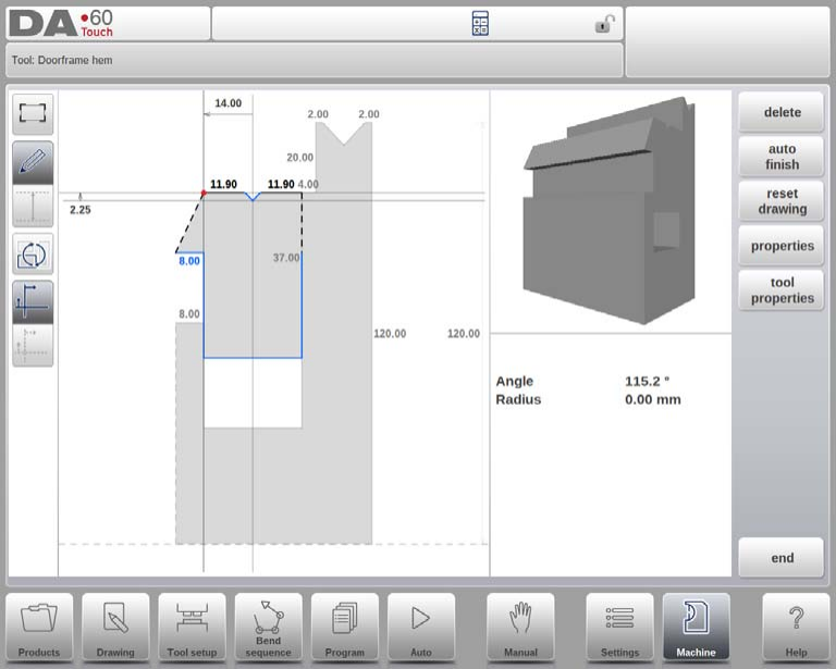
قالب حاشية إطار الباب
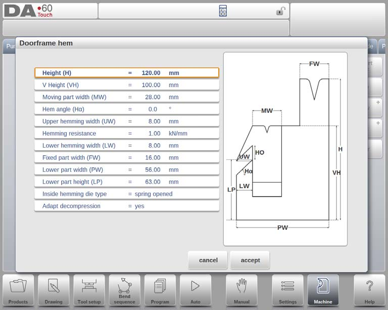
- الارتفاع (H): يؤدي هذا إلى تحديد الارتفاع الإجمالي للأداة وهو أمر حيوي لحساب عمق الانحناء.
- ارتفاع V (VH): يتم استخدامه أثناء عمليات الحاشية، ويحدد ارتفاع وحدة الحاشية.
- عرض الجزء المتحرك (MW): يقوم بتحديد عرض الجزء المتحرك أو وحدة الحاشية للقالب.
- زاوية الحافة (ها): زاوية وحدة الحاشية، وهي زاوية بالغة الأهمية للثني الدقيق.
- عرض الحاشية العلوية (UW): يقوم بتحديد عرض القطعة العلوية المستخدمة في الحاشية.
- فتحة الحاشية (HO): ارتفاع القالب عند فتحه، مما يسمح بوضع المنتج.
- مقاومة الحاشية: أقصى قوة يمكن أن تتحملها الأداة أثناء عملية الحاشية.
- عرض الحاشية السفلية (LW): عرض الجزء السفلي من القالب المشارك في عملية الحاشية.
- عرض الجزء الثابت (FW): عرض الجزء الثابت من القالب.
- عرض الجزء العلوي والسفلي: قم بتحديد أبعاد هذه الأجزاء من القالب.
- ارتفاع الجزء السفلي (LP): ارتفاع الجزء السفلي من القالب.
أنواع قوالب الحاشية الداخلية
- الربيع مفتوح:
- يستخدم زنبركًا داخليًا لوضع القالب في الاتجاه الأعلى في البداية.
- الانحناء المسبق: يتم وضع الورقة على قالب مفتوح للانحناء المسبق، مع حساب الزاوية المطلوبة.
- ثني الحافة: يتضمن وضع المنتج المثني مسبقًا في فتحة الحافة للثني النهائي.
- مفتوح ومغلق: مقفلة بشكل قياسي للثني العادي، غير مقفلة للثني.
- مغلق عادة: تظل القالب مغلقًا للانحناءات العادية؛ ويجب تنشيطه للثني.
تكييف الضغط: يُحدِّد ما إذا كانت قيمة فتح الحافة تُضيف إلى مسافة تخفيف الضغط، وهي ضرورية للقوالب المفتوحة بنابض. تشمل الخيارات "لا"، "نعم"، و"ثني هوائي".
خصائص فتح V
- نصف القطر، الزاوية V، الفتحة V: يقوم بتحديد نصف قطر الحافة وأبعاد فتح القالب.
- خيارات القاع V:
- 'المعيار': زاوية حادة.
- 'دائري': الجزء السفلي بنصف قطر محدد بواسطة 'نصف القطر الداخلي'.
- 'مسطح': قاع مسطح مع 'عرض سفلي' محدد.
رسم الأدوات واستيراد DXF
بعد ضبط هذه المعلمات، يمكنك إنشاء رسم أداة بإدخال قيم الزاوية وطول الخط. يدعم وضع الآلة في جهاز DELEM DA-69T استيراد DXF لقوالب حاشية إطار الباب، مما يضمن وجود جسم القالب في الطبقة 0 لضمان معالجة دقيقة.
قالب انحناء الجناح
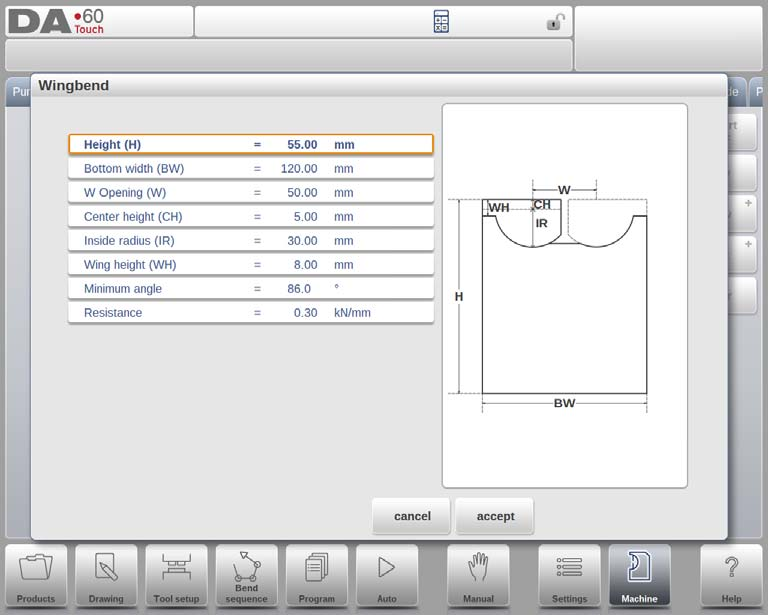
المعلمات الرئيسية:
- نقطة الدوران إلى المسافة العليا:ضروري لتحديد تشغيل الأداة من نقطة دورانها.
- نصف قطر الأجنحة: مهم لإجراء حسابات دقيقة للحركة.
- عرض الجناح:مهم لعمليات السحب الحسابية.
الأبعاد والميزات:
- الارتفاع (H):الارتفاع الإجمالي للأداة، وهو أمر بالغ الأهمية لحساب عمق الانحناء.
- عرض القاع (BW):عرض الأداة في وضع الماكينة DELEM DA-69T.
- افتتاح W (W):المسافة بين نقاط الدوران.
- ارتفاع المركز (CH):ارتفاع الجناح فوق نقطة الدوران الداخلية.
- نصف القطر الداخلي (IR):نصف قطر الجناح من نقطة الدوران الداخلية.
- ارتفاع الجناح (WH):جزء من ارتفاع الأداة الذي يشمل الجناح.
- الحد الأدنى للزاوية:أصغر زاوية يمكن تحقيقها باستخدام الأداة.
- مقاومة:القوة القصوى المسموح بها على الأداة.
خصائص وينجبيند
في وضع آلة DELEM DA-69T، تُعدّ خصائص أداة ثني الجناح أساسيةً للتخصيص والدقة. يُمكن تعديل هذه الخصائص بسهولة ضمن تعريف الأداة:
- العرض (W): يشير هذا إلى المسافة بين نقاط الدوران.
- ارتفاع المركز (CH): هذا هو ارتفاع الجناح فوق نقطة الدوران الداخلية.
- نصف القطر الداخلي (IR): نصف قطر الجناح من نقطة دورانه الداخلية.
- الفجوة (G): المسافة بين الجناحين لضمان عمل الأداة بشكل صحيح.
- عرض الجناح (WW): يحدد هذا عرض الجزء العلوي من الجناح.
- ارتفاع الجناح (WH): هذا هو ارتفاع الجناح ضمن تعريف ارتفاع الأداة، وهو ضروري لحركة الأداة.
- ارتفاع القاع (BH): يمثل ارتفاع الجزء الأوسط، وتحديدًا عمق فتحة V.
- الحد الأدنى للزاوية: أصغر زاوية يمكن ثنيها باستخدام أداة ثني الجناح هذه.
بعد تحديد هذه القيم، يمكنك إنشاء رسم أداة باستخدام أدوات الرسم المدمجة، بما في ذلك إدخالات الزاوية وطول الخط. توفر أدوات الرسم باللمس مرونةً تُضاهي أساليب رسم المنتجات.
استيراد DXF (اختياري)
في وضع آلة DELEM DA-69T، تتيح وظيفة استيراد DXF الاختيارية استيراد شكل قالب انحناء الجناح. انتبه لهذه النقاط:
- يجب أن يكون جسم القالب في الطبقة 0 من رسم DXF.
- يجب أن يكون الجناح، أو الجزء الدوار، في طبقة منفصلة. تسمية هذه الطبقة "جناح" تُمكّن من اختيار نوع الأداة تلقائيًا.
- يجب أن يكون كلا الجزأين في DXF محاطين بمحيطات مغلقة من أجل الاستيراد الصحيح.
استخدام وظائف الرسم
عند برمجة المثاقب والقوالب والمحولات وأشكال الآلات، يتيح التحكم رسم الأشكال بحرية لمزيد من الواقعية ومنع التصادم بدقة. يمكن للمستخدمين رسم الشكل المطلوب أولًا، ثم تعديل قيم المقاطع لاحقًا، أو تحديد المقاطع بدقة من البداية.
ومن المهم أن تعرف ما يلي:
في النهاية، يجب إغلاق هذه الأشكال. يُمكن لخاصية الإنهاء التلقائي أن تُساعد في ذلك.
• يُستخدم ارتفاع الجسم المُبرمج في حسابات الانحناء. تذكّر
أن هذا مهم جدًا للوصول إلى النتائج المرجوة.
قد يكون من المفيد معرفة ما يلي:
• يمكن إعطاء نصف قطر للخط وكذلك للزاوية.

- سيساعدك الالتقاط على محاذاة الخطوط والزوايا مع محيطها.
- يمكن استخدام طول الخط وأبعاد الإسقاط وزاويته للبرمجة. يُعدِّل نظام التحكم القيم بناءً على آخر إدخال، مُراعيًا اختلافات أبعاد الرسم المُقدَّمة لكل تفصيل من تفاصيل الشكل.

- تتيح لك خطوط المساعدة قياس المسافات بين النقاط وتعديلها حسب الحاجة. عند تحديد نقطة، ستظهر لك خطوط المساعدة؛ اضبطها لتحديد المسافة المطلوبة، وستتحرك النقطة وفقًا لذلك.
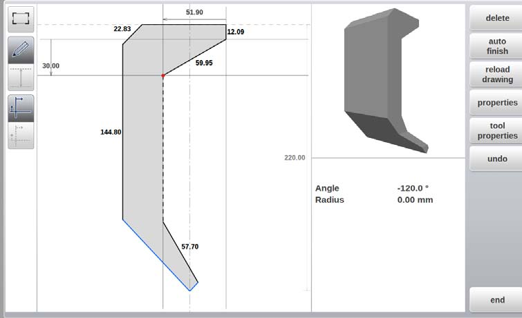
- لتسهيل الأمر عليك، يمكن إيقاف تشغيل خطوط المساعدة، مما يتيح لك رؤية ما رسمته دون أي إزعاج.
- في حال استخدام عنصر التحكم لنقاط التثبيت في تفاصيل الأداة، يُمكن تبديل نقاط التثبيت مع الرسم. هذا سيمنع التغييرات غير المرغوبة في موضع نقطة التثبيت أو تفاصيل الشكل.
استيراد DXF للأدوات والمحولات وأجزاء الآلات
تتضمن برمجة القواطع والقوالب في وضع آلة DELEM DA-69T استخدام وظيفة استيراد DXF، وهي أداة قياسية في DA-69T. تتيح لك هذه الميزة إضافة خطوط مخصصة إلى مكتبة أدوات الآلة، بما في ذلك القواطع والقوالب السفلية والمحولات.

ابدأ بفتح متصفح الملفات لاختيار ملف DXF يحتوي على الشكل المطلوب. اضبط إعدادات التحويل حسب الحاجة لاختيار طبقات محددة أو تضمين معلومات المحيط فقط. بعد اختيار "تحويل"، اختر بين الكشف التلقائي عن الشكل أو تحديد الشكل وتعيين مُعرِّف للأداة الجديدة.

تحرير الأدوات ودمج المكتبة
بعد التحويل، يُمكن تعديل الأداة لتفاصيل مثل الارتفاع ونقاط التركيب. بعد الانتهاء، تُضاف إلى مكتبة الأدوات للاستخدام.
تحويل أداة متعددة الخطوط
بالنسبة للأدوات ذات الخطوط المتعددة، تأكد من ضبط طبقة الجسم الرئيسي على 0، بينما توضع الأجزاء الأخرى، مثل قوالب الحاشية أو ثنيات الأجنحة، على طبقات منفصلة مُسمّاة وفقًا لذلك. يجب أن يكون لكلا الجزأين خطوط مغلقة في ملف DXF لاستيراد ناجح.
تحسين عمليات الآلة باستخدام المنقلة وتسجيل الأحداث
منقلة

باستخدام هذه المعلمة، يمكنك تحديد جهاز قياس الزاوية الرقمي عند تثبيت خيار المنقلة.
جهاز قياس الزاوية
يتكامل وضع الماكينة DELEM DA-69T مع أجهزة قياس الزاوية لإنتاج دقيق:
- غير مستخدم:لا يتطلب أي جهاز خارجي.
- ميتوتويو 187-50x:يضمن قياسات موثوقة.
- Mit.187-50x U-WAVE:يظهر عند اكتشاف جهاز استقبال لاسلكي.
- اي بي ار:يدعم مختلف العلامات التجارية للمنقلة.
استخدم هذه الأجهزة في وضع الإنتاج لضمان الدقة. ضع المؤشر على حقل تصحيح ألفا، ثم فعّل زر الإرسال في الجهاز. سيعرض جهاز DELEM DA-69T الزاوية. اضغط على زر الإدخال لقبول التصحيحات اللازمة وحسابها.
إدخال تلقائي للتصحيح.α
- عن:يظهر تصحيح الزاوية، والذي يتطلب التحديد اليدوي والتأكيد.
- على:يتم إجراء التصحيحات تلقائيًا؛ ولا يلزم إدخال يدوي في وضع الجهاز DELEM DA-69T.
تسامح الزاوية
يُحدد أقصى انحراف بين الزوايا المُبرمجة والمقاسة. تُؤدي الاختلافات الكبيرة إلى حدوث خطأ. عند تفعيل "إدخال التصحيح التلقائي α"، تتوقف التصحيحات التلقائية في حال تجاوز التسامح.
حساب الزاوية
- 180-α:الزاوية هي المكمل لزاوية الحاصل.
- ألفا:الزاوية تطابق زاوية المنتج.
تسجيل الأحداث
من أهم ميزات وضع الآلة في جهاز DELEM DA-69T قدرته على تسجيل الأحداث لإدارة الإنتاج. تُمكّن هذه الوظيفة المستخدمين من تسجيل أحداث مُحددة على وحدة التحكم وتخزينها في ملفات نصية لمراجعتها لاحقًا. يُعدّ فهم كيفية ضبط هذه المعلمات أمرًا بالغ الأهمية لإدارة عمليات الإنتاج بكفاءة وتحسينها.

تسجيل الأحداث: تشغيل/إيقاف التبديل
- اسم الملف: عيّن اسمًا لملف السجل. سيُضيف النظام امتداد ".txt" تلقائيًا.
- اختيار المسار: اختر مكان تخزين ملفات السجل. تشمل الخيارات الذاكرة الداخلية، أو ذاكرة USB، أو محرك أقراص الشبكة. استخدم وظيفة "تحديد المسار" لتحديد الموقع المُفضّل.
- الحد الأقصى لحجم الملف: حدد الحد الأقصى لحجم كل ملف سجل بالكيلوبايت. عند الوصول إلى هذا الحد، يُغلق الملف ويُنشأ ملف جديد. هذا يضمن استمرارية عملية التسجيل دون فقدان أي بيانات.
معلمات تسجيل الأحداث:
- بدء تشغيل وحدة التحكم: تسجيل الدخول عند بدء التحكم.
- توقف وحدة التحكم: تسجيل الدخول عند إيقاف التحكم.
- تغيير الخطوة: ينتقل السجل إلى خطوة الانحناء التالية.
- المنتج مكتمل: يسجل اكتمال الخطوة الأخيرة في برنامج الانحناء.
- تغيير الوضع: تسجيل الدخول عند تحديد وضع مختلف.
- رسالة الخطأ: يسجل حدوث رسائل الخطأ.
هيكل ملف السجل

يتضمن كل سطر حدث في ملف السجل طابعًا زمنيًا وطبيعة الحدث. على سبيل المثال:
- مثال:
<log time="20100129T122021.477" event="mode" mode="1"/>
تم تنسيق الوقت على النحو التالي وقت السجل= ت، مع عرض التاريخ بالسنة-الشهر-التاريخ والوقت بالساعات-الدقائق-الثواني-الملي ثانية، مفصولين بحرف "T". يتم تحديد طبيعة الحدث بكلمات مفتاحية، مثل:
- تغيير الوضع: تتضمن السمات رقم الوضع حيث
1 = يدوي,2 = البرمجة,3 = تلقائي,4 = خطوة بخطوة. - تغيير الخطوة: قد تتضمن السمات معرف المنتج ورقم الخطوة.
- البدء/الإيقاف: تتضمن السمات معرف المنتج ورقم الخطوة وعداد المخزون.
- المنتج مكتمل: تتضمن السمات معرف المنتج وعداد المخزون.
- رسالة الخطأ: السمة هي رقم الخطأ.
اعتبارات تخزين الملفات
بما أن كل سطر سجل يستغرق حوالي 50 بايت، فإن ملفًا بحجم 10 كيلوبايت يمكنه تسجيل حوالي 200 حدث. للتسجيل المكثف، يُنصح باستخدام وحدة تخزين خارجية مثل ذاكرة USB أو موقع شبكي، يدعم حجم ملف يصل إلى 1 ميجابايت، أي ما يعادل حوالي 20,000 حدث.
دمج معلومات النظام ونصائح الصيانة
معلومات النظام
لبرمجة عمليات الثقب والموت بشكل فعال في وضع الماكينة DELEM DA-69T، فإن الإلمام بميزات علامة التبويب النظام أمر ضروري للتعامل السلس مع البرامج وتحسين الماكينة.

توفر علامة تبويب نظام وضع الماكينة DELEM DA-69T تفاصيل حيوية، مثل إصدارات البرامج ومعرفات الوحدات المثبتة - وهي ضرورية لمهام الصيانة والخدمة.
الوظائف والميزات الرئيسية
- طلب:يعرض إصدار التطبيق الحالي على جهاز DELEM DA-69T.
- معرف الخيار:معرف خيار التحكم الفريد لجهازك.
- المُسلسل:يظهر إصدار التسلسل الحالي الضروري لبرمجة التسلسلات.
- ديليم.ديف: يشير إلى إصدار ملف delem.def الجاري تشغيله.
- الوحدات النمطية:تسرد معرفات الوحدات وإصدارات الفلاش، مع إمكانية الوصول إلى أكثر من أربعة عناصر.
إدارة البرمجيات والنظام
- تحديث البرنامج:قم بتثبيت التحديثات عبر USB، باستخدام متصفح الدليل للاختيار.
- نظام النسخ الاحتياطي:قم بإجراء نسخ احتياطية كاملة للنظام على عصا USB، بما في ذلك برنامج Delem، وبيانات OEM، وملفات المستخدم.
- استعادة النظام:استعادة النسخ الاحتياطية السابقة باستخدام استعادة المكونات القابلة للتحديد.
- برامج غير متصلة بالإنترنت:إنشاء ملفات إعداد البرامج دون اتصال بالإنترنت على USB، مما يضمن التوافق مع برنامج التحكم للحصول على وظيفة مثالية.
صيانة
يوضح هذا القسم وظائف الصيانة المتوفرة في وضع آلة DELEM DA-69T. تُعد هذه الميزات أساسية لضمان كفاءة تشغيل آلتك وطول عمرها.

الساعات والضربات
- ساعات:يعرض إجمالي ساعات تشغيل الماكينة، وهو أمر بالغ الأهمية لجدولة الصيانة.
- السكتات الدماغية: يشير إلى عدد الضربات التي نفذها شعاع الضغط، مما يوفر نظرة عامة على استخدام الماكينة.
وضع التشخيص
- التنشيط:وضع التشخيص ضروري لأغراض الصيانة. يمكن تفعيله بإدخال رمز خاص، مما يتطلب التواصل مع الشركة المصنعة للجهاز للحصول على رمز الوصول اللازم.
- إلغاء التنشيط:لإلغاء التنشيط، قم ببساطة ببرمجة "0" في نفس الحقل.
إدارة الشاشة
- معايرة شاشة اللمس:ضبط إعدادات معايرة الشاشة لتتوافق مع تفضيلات المستخدم لتحقيق التفاعل الأمثل.
- شاشة القفلاستخدم وظيفة قفل الشاشة لمنع التغييرات أثناء التنظيف. يتم إلغاء القفل بالضغط على زر "إيقاف".
إنشاء ملف .dat
- إنشاء ملف dat في وضع التشخيص يُساعد في توثيق بيانات المنتج والتحكم المهمة. يُخزَّن هذا الملف تلقائيًا على ذاكرة USB المتصلة، وهو ضروري لدعم الصيانة.
استبدال الوحدة
يمكن تنفيذ عملية استبدال وحدات المحور في جهاز DELEM DA-69T دون الحاجة إلى وصول متخصص، باتباع الخطوات التالية:
- إيقاف التشغيل وفصل الاتصال:قم بإيقاف تشغيل جهاز التحكم DA وفصل وحدة DM التي تتطلب الاستبدال.
- توصيل الوحدة الجديدة:قم بتوصيل وحدة DM الجديدة من نفس النوع وقم بتشغيل الجهاز.
- رسالة الخطأ:ستظهر رسالة خطأ تعرض معرف الوحدة الأصلية.
- وضع الوصول إلى الجهاز:ادخل إلى وضع الماكينة وانتقل إلى علامة التبويب الصيانة.
- تثبيت الوحدة النمطية:انقر فوق تثبيت الوحدة عند مطالبتك بذلك.
- تأكيدستظهر نافذة تطلب تأكيد استبدال الوحدة. انقر "نعم" للمتابعة.
- إعادة التشغيل والتحديث:سيتم إعادة تشغيل جهاز التحكم لتهيئة الوحدة الجديدة، وستحدث تحديثات البرامج الضرورية تلقائيًا.
الأسئلة الشائعة
ماذا يجب أن أفعل إذا واجهت رسالة خطأ أثناء استخدام وضع الجهاز DELEM DA-69T؟
إذا واجهت رسالة خطأ في وضع جهاز DELEM DA-69T، فراجع دليل الجهاز للحصول على نصائح لاستكشاف الأخطاء وإصلاحها. غالبًا ما يمكن حل المشكلات الشائعة بالتحقق من تحديثات البرامج أو التأكد من صحة جميع التوصيلات والإعدادات.
ما هي أفضل طريقة لبرمجة الأشكال المعقدة في وضع آلة DELEM DA-69T؟
للأشكال المعقدة، استخدم الواجهة الرسومية لوضع آلة DELEM DA-69T. قسّم الشكل إلى مكونات أبسط واستخدم خيارات البرمجة خطوة بخطوة. كما أن اختبار النموذج الأولي باستخدام مواد خام يُحسّن العملية.
هل يمكنني حفظ البرامج المخصصة في وضع الجهاز DELEM DA-69T لاستخدامها في المستقبل؟
نعم، يتيح لك وضع الآلة في جهاز DELEM DA-69T حفظ برامج الثقب والقوالب المخصصة. هذه الميزة مفيدة بشكل خاص للعمليات المتكررة، حيث تتيح إعدادًا سريعًا ونتائج متسقة.
خاتمة
لإتقان برمجة الثقب والقوالب في وضع آلة DELEM DA-69T، من الضروري فهم واجهة الآلة، وضبط معلمات الأداة بدقة، وتطبيق التسلسل الصحيح لعملياتك. هذه الخطوات أساسية لضمان الأداء الأمثل للآلة ودقتها في مشاريعك.
بالالتزام بهذه الإرشادات، يمكنك تعزيز إنتاجيتك وتقليل الأخطاء التشغيلية. طبّق هذه الاستراتيجيات لتحقيق أقصى استفادة من إمكانيات جهاز DELEM DA-69T الخاص بك.
لمزيد من المساعدة أو للتعمق في وظائف وضع الآلة DELEM DA-69T، لا تترددوا في التواصل مع فريقنا. كما يمكنكم الاطلاع على وثائقنا الأخرى لمزيد من المعلومات حول كيفية تعظيم إمكانات معداتكم.


