


Zrozumienie maszyna do strzyżenia safety guards and interlock system requirements is essential for preventing catastrophic workplace injuries during metal fabrication. A maszyna do strzyżenia uses a high-pressure hydraulic or mechanical force to cut sheet metal, creating significant pinch points and blade hazards. This guide applies to operators, maintenance technicians, and safety officers responsible for HARSLE hydraulic shears, focusing on the integrated physical barriers and electronic monitoring systems designed to halt operation if a safety breach occurs.
Scope, Responsibilities, and Training Prerequisites
The implementation of safety protocols for shearing machines is a shared responsibility between the facility management and the equipment operators. Before any individual is permitted to operate a HARSLE shearing machine, they must undergo rigorous training that covers the specific mechanics of the model in use, whether it is a swing beam shear (QC12Y) or a guillotine shear (QC11K).
Operator Prerequisites
- Technical Competency: Operators must understand the machine’s capacity limits, including maximum material thickness and tensile strength, to prevent mechanical failure that could bypass safety guards.
- Safety Awareness: Completion of a verified Hazard Communication (HAZCOM) and Personal Protective Equipment (PPE) training module.
- Manual Familiarity: Direct review of the HARSLE model-specific manual, focusing on the location of all Emergency Stop (E-stop) buttons and interlock reset procedures.
Qualified Personnel vs. Operators
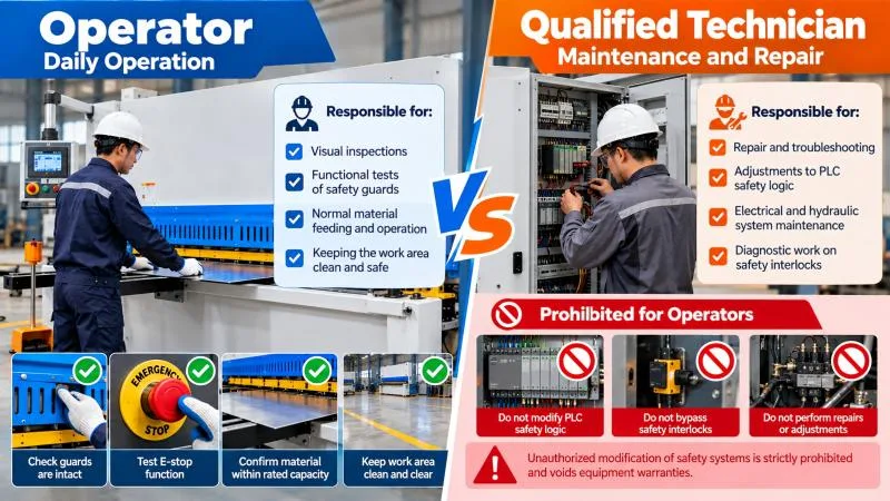
It is critical to distinguish between daily operation and system maintenance. Operators are responsible for visual inspections and functional tests of guards. However, any repair, adjustment to the PLC (Programmable Logic Controller) safety logic, or bypass of a faulty interlock for diagnostic purposes must be performed exclusively by qualified electrical or hydraulic technicians. Unauthorized modification of safety systems is strictly prohibited and voids equipment warranties.
Hazard and Control Measure Table
The following table outlines the primary hazards associated with industrial shearing and the corresponding engineering or administrative controls required to mitigate risk.
| Hazard Type | Description of Risk | Control Measure / Safeguard |
|---|---|---|
| Point of Operation | Amputation or crushing from contact with the descending blade or hold-downs. | Fixed front finger guards and interlocked light curtains. |
| Rear Discharge Zone | Injury from falling off-cuts or contact with the backgauge mechanism. | Rear physical fencing with interlocked access gates. |
| Hydraulic Failure | Unintended blade descent due to pressure loss or valve malfunction. | Hydraulic safety blocks and dual-monitored valves. |
| Material Kickback | Sheet metal flipping or sliding unexpectedly during the stroke. | Properly adjusted hold-down cylinders and shadow line lighting for alignment. |
| Electrical Fault | Short circuits leading to unexpected machine activation. | IP54-rated control cabinets and grounded interlock circuits. |
The Anatomy of Shearing Machine Safety Guards
Safety guards on a shearing machine are not merely covers; they are engineered barriers designed to prevent any part of the operator’s body from entering the “danger zone” during the cutting cycle. These systems are categorized into three primary types.
1. Fixed Front Finger Guards
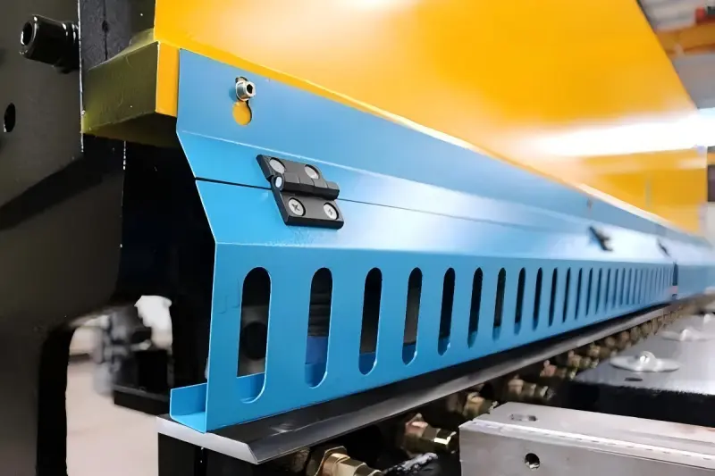
The front guard is a stationary barrier located before the hold-down cylinders. It is designed with specific slot dimensions that allow the workpiece to pass through to the blade while remaining narrow enough to prevent fingers from reaching the pinch points. These must be securely bolted and never removed during operation. If a slot is bent or widened, the guard must be replaced immediately.
2. Side and Rear Fencing
The sides and rear of the shearing machine house the backgauge motor, drive belts, and the area where finished parts are discharged. These areas must be enclosed by heavy-duty wire mesh or solid panels. The rear area is particularly dangerous because the backgauge moves automatically based on the CNC program. Access to this area should be restricted via interlocked gates that kill power to the motor when opened.
3. Optoelectronic Protective Devices (Light Curtains)
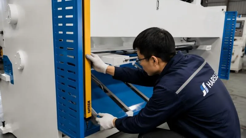
Modern HARSLE shears often utilize light curtains as a secondary layer of protection. These devices project an array of infrared beams across the throat of the machine or the rear discharge area. If the beam is broken, the interlock system sends a signal to the hydraulic safety valve to stop the blade movement instantly. This is especially useful for applications where fixed guards might obstruct complex material handling.
Interlock System Requirements and Logic
An interlock is a device that prevents a machine from operating under specific conditions. In shearing machines, the interlock system links the physical guards to the machine’s control circuit. Understanding the logic of these systems is vital for safe operation.
Electrical Interlock Logic
Most safety interlocks operate on a “normally closed” (NC) circuit. This means that when the guard is closed, the circuit is complete, allowing electricity to flow to the start command. If a guard is opened, the circuit is broken (opened), and the machine loses the “run” signal. This “fail-safe” design ensures that if a wire is cut or a switch fails, the machine will default to a stopped state rather than a running state.
Hydraulic Interlocks
In addition to electrical stops, hydraulic shears utilize safety valves. These valves are often redundant (dual-channel). Even if the electrical system signals a stop, the hydraulic safety block provides a physical backup by diverting oil flow away from the main cylinders and back to the tank, preventing the blade from completing a stroke.
Pre-Operation Safety Checklist
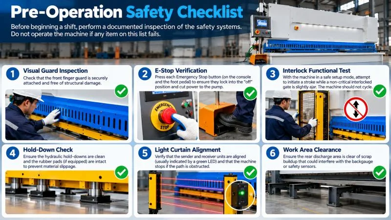
Before beginning a shift, the operator must perform a documented inspection of the safety systems. Do not operate the machine if any item on this list fails.
- Visual Guard Inspection: Check that the front finger guard is securely attached and free of structural damage.
- E-Stop Verification: Press each Emergency Stop button (on the console and the foot pedal) to ensure they lock into the “off” position and cut power to the pump.
- Interlock Functional Test: With the machine in a safe setup mode, attempt to initiate a stroke while a non-critical interlocked gate is slightly ajar. The machine should not cycle.
- Hold-Down Check: Ensure the hydraulic hold-downs are clean and the rubber pads (if equipped) are intact to prevent material slippage.
- Light Curtain Alignment: Verify that the sender and receiver units are aligned (usually indicated by a green LED) and that the machine stops if the path is obstructed.
- Work Area Clearance: Ensure the rear discharge area is clear of scrap buildup that could interfere with the backgauge or safety sensors.
Safe Operation Boundaries and Stop Conditions
Operating within the designed boundaries of the machine is a core component of safety. Overloading the machine or using it for unintended purposes can cause structural failures that safety guards cannot contain.
Material Limitations
Always verify the material thickness against the machine’s rating plate. Shearing material that is too thick or has a higher tensile strength than specified (e.g., attempting to cut stainless steel on a machine rated only for mild steel at that thickness) can cause the blade to deflect or the frame to stress, potentially ejecting metal shards.
Environmental Conditions
The machine should be operated in a well-lit environment to ensure the shadow line (if equipped) is visible for accurate and safe positioning. The floor must be kept free of oil and debris to prevent slips, which are particularly dangerous near the foot pedal control.
Immediate Stop Conditions
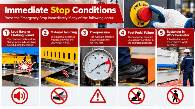
Operators must immediately trigger the E-stop and notify a supervisor if any of the following occur:
- Unusual rhythmic banging or grinding noises.
- Visible hydraulic oil leaks near the cylinders or valves.
- The blade “drifts” downward while the machine is idling.
- The backgauge moves erratically or fails to respond to CNC commands.
- Any safety guard becomes loose or vibrates excessively.
Emergency Response and Qualified-Personnel Escalation
In the event of a safety system failure or an accident, following a structured response plan is critical. The primary goal is to neutralize the energy sources and provide assistance without creating further hazards.
Emergency Stop Procedure
- Actuate E-Stop: Immediately hit the nearest Emergency Stop button.
- Power Isolation: Turn off the main isolator switch on the electrical cabinet.
- Lockout/Tagout (LOTO): Apply a personal lock and tag to the isolator to ensure the machine cannot be restarted while the situation is assessed.
- Report: Notify the safety officer and maintenance department.
When to Call a Qualified Technician
Operators should never attempt to troubleshoot the internal electronics or hydraulic manifolds. Escalation to qualified personnel is required when:
- The PLC displays a “Safety Circuit Fault” that does not clear after a standard reset.
- A light curtain remains in a fault state (red light) despite no obstructions.
- The hydraulic pressure gauge shows abnormal readings (too high or too low).
- The blade gap adjustment mechanism is jammed.
Safety FAQs
Can I temporarily bypass an interlock to cut an oversized sheet?
No. Bypassing a safety interlock is a severe violation of safety protocols and significantly increases the risk of amputation. If a sheet does not fit within the guarded area, it must be cut using a different machine or the guards must be professionally adjusted by a qualified person to a safe, compliant configuration that still protects the operator.
How often should the safety interlock system be tested?
Functional tests of the interlock system should be performed at the start of every shift. A comprehensive inspection by a certified technician should be conducted annually or semi-annually, depending on the machine’s usage volume and the manufacturer’s recommendations in the HARSLE manual.
What should I do if the light curtain stops the machine frequently?
Frequent tripping usually indicates either a misalignment of the sensors, excessive dust/debris on the lenses, or improper material handling techniques. Clean the lenses with a soft, dry cloth and ensure the work area is clear. If the problem persists, the system may require recalibration by a technician.
Safety Review Checklist and Model-Manual References
To maintain a safe working environment, use this final review checklist in conjunction with your HARSLE QC11K or QC12Y technical manual.
- Manual Reference: Consult Section 4 (Safety Instructions) of your HARSLE manual for specific torque specs on guard bolts.
- Signage: Ensure all warning decals (e.g., “Crush Hazard,” “High Voltage”) are legible and in the correct language for the operators.
- PPE Compliance: Verify that all operators are wearing safety glasses, cut-resistant gloves, and steel-toed boots.
- Blade Maintenance: Ensure blades are sharp; dull blades require more pressure and increase the risk of material slippage and machine stress.
- Documentation: Maintain a logbook of all safety tests, interlock trips, and maintenance actions performed on the safety systems.
For further technical support or to order replacement safety components for your shearing machine, contact your authorized HARSLE service representative. Always prioritize operator safety over production speed.


