


Интегрированная САПР ESA S630 — это мощный инструмент для расширения возможностей проектирования как для дизайнеров, так и для инженеров. Если вам интересно узнать, как эта интегрированная САПР может вывести процесс проектирования на новый уровень, вы обратились по адресу.
В этой статье я подробно расскажу об уникальных возможностях интегрированной САПР ESA S630 и объясню, как она может оптимизировать ваш рабочий процесс и повысить точность проектирования. Независимо от того, новичок ли вы в использовании САПР или хотите оптимизировать свои текущие системы, это руководство предоставит вам ценную информацию об использовании интегрированной САПР ESA S630 для достижения превосходных результатов проектирования.
Введение
Интегрированная система автоматизированного проектирования ESA S630 предлагает мощные функции, оптимизирующие процессы проектирования, особенно для металлообработки на листогибочных прессах. Её отличительной особенностью является возможность построения основных графических элементов, таких как нижняя и верхняя части станка, пуансон, матрица и изгибаемая деталь. Эта интеграция позволяет пользователям эффективно проверять последовательности гибки, минимизируя ошибки и оптимизируя рабочий процесс. Краткое руководство обеспечивает лёгкий доступ к этим функциям проектирования, позволяя пользователям максимально использовать потенциал интегрированной системы автоматизированного проектирования ESA S630 для повышения точности и эффективности проектирования.
Функция рисования
Функция рисования в ЕКА S630 Интегрированная система автоматизированного проектирования значительно упрощает и ускоряет начальные этапы проектирования. Эта функция позволяет трассировать линейные сегменты по введенным оператором данным, что повышает как скорость, так и точность. Интегрированная система автоматизированного проектирования ESA S630 поддерживает ввод данных в полярных и декартовых координатах, при этом предпочтение отдается полярному формату из-за его удобства. Такая гибкость обеспечивает точность и снижает вероятность ошибок, делая функцию черчения незаменимым инструментом для эффективного и точного проектирования.
Полярная настройка данных чертежа
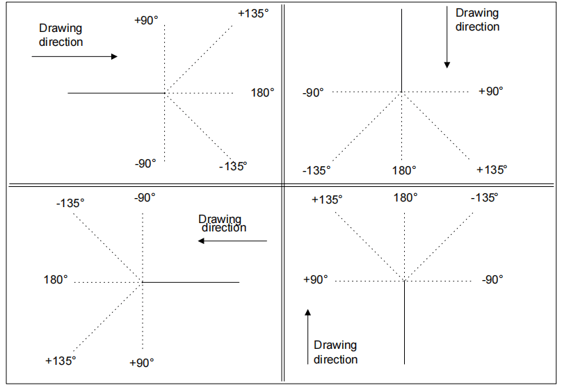
Функция установки полярных координат в интегрированной системе автоматизированного проектирования ESA S630 крайне важна для повышения точности проектирования, особенно в сложных проектах. Задавая сечения чертежа по длине и углу (в диапазоне ±180,0°), эта функция обеспечивает точное выравнивание. Она особенно полезна в ситуациях, требующих точных измерений, например, при проектировании архитектуры или машиностроения.
Условные обозначения, с которыми следует вводить эти углы, следующие:
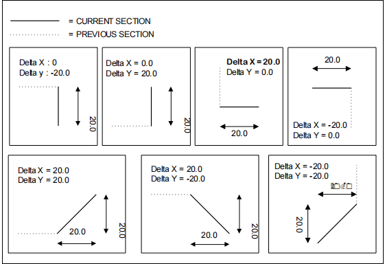
Декартова установка данных чертежа
Эта функция позволяет определить секции, которые будут составлять чертеж, с помощью пары координат, которые идентифицируют разницу между началом и концом сегмента.
Декартовы координаты не являются абсолютными, а относятся к началу сегмента, и их необходимо ввести.
Общие данные
Перед началом рисования графического элемента необходимо ввести некоторые общие данные, которые будут меняться в зависимости от объекта, который вы хотите нарисовать.
Данные, которые необходимо ввести на этом этапе, описаны в соответствующих главах для каждого объекта.
Страница рисования
Страница чертежей в интегрированной системе автоматизированного проектирования ESA S630 — это краеугольный камень её удобного дизайна, разработанный для улучшения организации и доступности проектных данных. Чтобы открыть интерфейс чертежей, просто выберите [Ok] кнопку пальцем — этот интуитивный доступ — только начало продуманного дизайна.
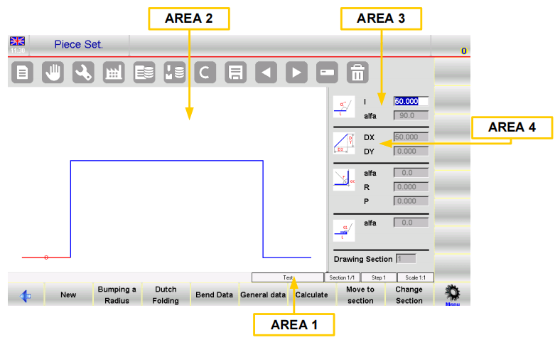
Страница чертежей разделена на несколько отдельных областей:
- Область 1: Информация о чертеже или строка состояния: В этом окне отображается важная информация, такая как название программы, над которой вы работаете, номер раздела и шага текущего чертежа, а также масштабный коэффициент. Эта информация в режиме реального времени позволяет вам всегда быть в курсе особенностей процесса проектирования.
- Область 2: Окно графической трассировки: Здесь графическое представление вашего рисунка оживает на основе введённых данных. Он служит визуальным центром, где ваши замыслы обретают форму, мгновенно отражая ваши идеи.
- Область 3: Окно полярной настройки: Эта область позволяет вводить точные данные, касающиеся длины стороны, которую нужно нарисовать ('л') и угол ('Альфа') по сравнению со следующей стороной. Полярная настройка повышает точность и гибкость, необходимые для сложных конструкций.
- Область 4: Окно декартовой настройки: В этом окне можно ввести декартовы координаты («DX» и «DY»). Эти координаты отражают разницу между начальной и конечной координатами отрезка, который нужно нарисовать, добавляя ещё один уровень точности вашему проекту.
Продуманная организация окон не только оптимизирует процесс черчения, но и значительно улучшает доступность и управление проектными данными. Благодаря интегрированной странице чертежей САПР ESA S630 проектировщики получают комплексный и интуитивно понятный интерфейс, который способствует эффективной и точной разработке проектов.
Ввод данных чертежа
Точный и эффективный ввод данных — критически важный аспект создания точных проектов, и интегрированная система автоматизированного проектирования ESA S630 превосходна в этом отношении благодаря интуитивно понятному вводу данных. При первом открытии чертежа в области 2 стандартная длина первой стороны автоматически отображается и выделяется красным цветом, что позволяет легко проверить и скорректировать начальные настройки. Исходное направление можно быстро изменить, перейдя к [Подменю] и выбрав [Вращение], обеспечивая гибкость процесса проектирования.
Как ввести чертеж в полярном режиме
Если курсор не находится в поле «л» Зоны 3 необходимо будет нажать кнопку [Подменю] и [Полярный формат] Для активации полярного типа необходимо ввести следующие значения:
- Длина стороны; сторона будет масштабироваться в зависимости от введенной длины, и курсор переместится на "альфа" Поле для установки угла.
- Угол по сравнению со следующей длиной.
Длина, указанная выше, станет синей; будет нарисована следующая длина, которая станет текущей и будет показана красным цветом. Текущий участок будет обведен кружком.
После завершения ввода данных курсор перемещается в поле для задания длины новой стороны. Ввод этой пары данных необходимо повторять до завершения чертежа.
Обновление информации о розыгрыше
Если введенные размеры превышают размеры окна, чертеж автоматически масштабируется; масштабный коэффициент чертежа в Области 1 обновляется.
Каждый раз, когда рисуется новая длина, в поле «» отображается номер текущей длины.шаг" Поле Зоны 1 будет увеличено.
Заверши рисунок
Чтобы обозначить, что рисунок закончен, необходимо установить угол последней длины равным нулю.
Как выбрать данные для чертежа
Для выбора данных чертежа необходимо прокручивать их с помощью этих двух кнопок


Кнопка прокручивает данные, составляющие рисунок, в обратном порядке, переходя шаг за шагом между "альфа" и «л» Поле. Прокручивает данные в последовательном режиме, проходя шаг за шагом «л» Поле. При прокрутке данных чертежа длина, соответствующая отображаемым данным, будет подсвечена, а также номер текущего шаг будет отображаться в Зоне 1.
Изменить данные чертежа
Для изменения данных чертежа необходимо:
- выберите значение.
- введите новое значение.
- нажмите [Ok] принять новое значение.
- чертеж будет прорисован в зависимости от нового введенного значения.
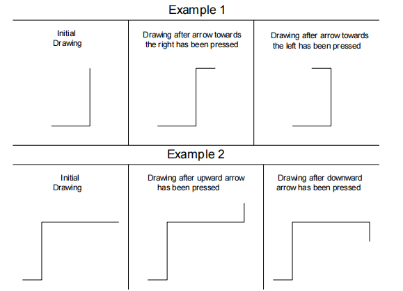
Использование стрелок направления на виртуальной клавиатуре
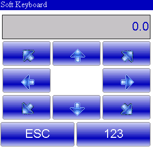
Клавиши со стрелками перемещают длину по горизонтали или вертикали.
Использование стрелок и клавиш внешней клавиатуры
В нашем ЧПУ возможно ли подключить внешнюю клавиатуру PS2 или USB?
Клавиши со стрелками перемещаются по сегментам по диагонали.
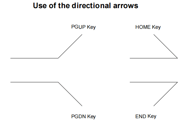
Существующий угол автоматически вводится в "альфа" Поле между текущей длиной и стороной трассировки в зависимости от нажатой клавиши направления.
Как удалить длину чертежа
В интегрированной системе автоматизированного проектирования ESA S630 удаление отрезка осуществляется выбором нужного участка и нажатием кнопки. Удалённый отрезок корректирует следующий отрезок на основе предыдущего угла.

Если удалить последнюю длину, она по умолчанию будет стандартной. Чтобы удалить последнюю длину, перейдите к предыдущим данным перед завершением чертежа.
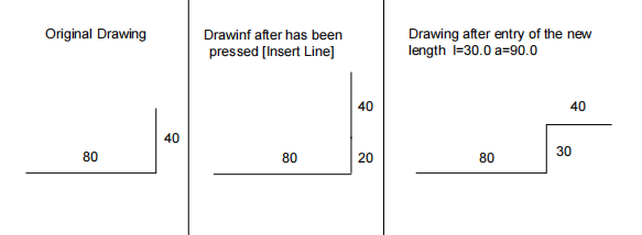
Как ввести длину на чертеже
В интегрированной системе автоматизированного проектирования ESA S630 добавление новой длины выполняется очень просто. Для этого нажмите соответствующую кнопку и выберите «1>> Вставить», вы можете добавить длину перед текущей. Новая длина изначально будет стандартной, фактически увеличивая текущую длину на 20 мм. Чтобы получить желаемые параметры чертежа, просто введите необходимые значения новой длины.
Если у вас возникли проблемы с использованием функции вставки, практичным подходом будет перейти к точке вставки, удалить все последующие длины и перерисовать чертеж.
Как использовать декартов формат
Для оптимизации процесса проектирования с помощью интегрированной системы автоматизированного проектирования ESA S630 критически важно эффективно использовать декартов формат. Если полярный формат невозможен, интегрированная система автоматизированного проектирования ESA S630 позволяет определять сегменты в декартовом формате.
Просто нажмите [Подменю] а потом [Картезианский редактор] на желаемой длине рисунка. В области 4 введите разницу по горизонтали ДХ поле и вертикальная разница в ДЙ поле, подтверждая каждое с помощью [Ok].

Чтобы вернуться к полярному формату, нажмите [Полярный редактор]. Такая гибкость интегрированной системы автоматизированного проектирования ESA S630 позволяет эффективно адаптировать ваши проекты, обеспечивая точность и оптимизируя рабочий процесс.
Часто задаваемые вопросы (FAQ)
Каким образом интегрированная система автоматизированного проектирования ESA S630 повышает точность проектных чертежей?
Интегрированная система автоматизированного проектирования ESA S630 предлагает расширенные функции черчения и полярные настройки, которые значительно повышают точность. Программа позволяет проектировщикам вводить точные размеры и применять полярные координаты, обеспечивая высокую точность и детализацию сложных проектов.
Может ли интегрированная система автоматизированного проектирования ESA S630 помочь упростить ввод данных чертежей?
Да, интегрированная система автоматизированного проектирования ESA S630 оснащена интуитивно понятными функциями ввода данных, которые минимизируют ошибки и повышают эффективность. Эта функция помогает проектировщикам эффективно вводить и организовывать данные, делая процесс проектирования более быстрым и надежным.
Как часто следует обновлять программное обеспечение интегрированной системы автоматизированного проектирования ESA S630 для достижения наилучшей производительности?
Рекомендуется регулярно проверять наличие обновлений, в идеале — раз в квартал. Обновления часто включают в себя новые функции, улучшения производительности и исправления ошибок, которые могут оптимизировать процесс проектирования и обеспечить совместимость с другим программным обеспечением и операционными системами.
Заключение
Подводя итог, можно сказать, что интегрированная система автоматизированного проектирования ESA S630 предлагает ряд мощных функций, значительно оптимизирующих процесс проектирования. Благодаря широкому спектру функций черчения, точным настройкам полярных координат, интуитивно понятному интерфейсу страницы чертежа и эффективным возможностям ввода данных, проектировщики могут оптимизировать свой рабочий процесс, повысить точность и, в конечном итоге, создавать более качественные проекты. Сочетание этих ключевых элементов делает ESA S630 незаменимым инструментом для любого современного проекта.
Тем, кто стремится оптимизировать эффективность и точность проектирования с помощью интегрированной системы автоматизированного проектирования ESA S630, мы рекомендуем ознакомиться с дополнительными ресурсами на нашем сайте. Если у вас возникнут вопросы или вам потребуется индивидуальная консультация, пожалуйста, свяжитесь с нашей командой. Мы готовы помочь вам максимально эффективно использовать потенциал ваших процессов проектирования с помощью интегрированной системы автоматизированного проектирования ESA S630.


