Technical Specification For 2000T Hydraulic Press
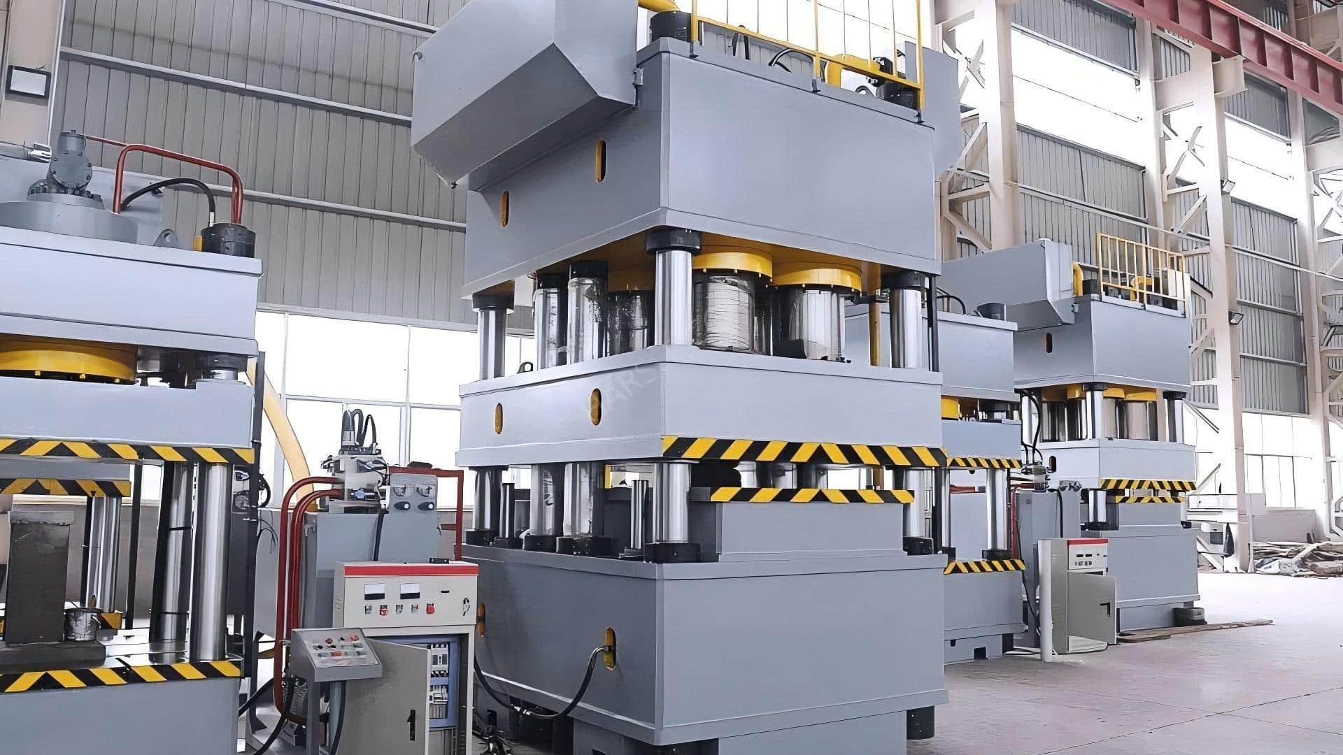
Table of Contents
1. Introduction
This specification covers the general requirements of two numbers of 2000T hydraulic presses which include design, manufacturing, supply, erection, commissioning and testing of the presses at NFC. The 2000T hydraulic presses are required to compact the zirconium metal sponge of various sizes and shapes (As per specifications given below).
2. Scope of supply
The scope of supply include design, manufacturing, supply, erection, commissioning and testing of two (2) numbers of down-stroking hydraulic presses used for making compacts of zirconium sponge. Any additional items or sub systems which are not mentioned in the specifications but required or identified for the completeness and trouble-free performance of the system shall be included in the scope without additional price and time implications.
3. Description
Dimensions of various zirconium sponge compacts to be produced are as following:
1. Cylindrical compact of 180 mm diameter and 135 mm height.
2 .Cylindrical compact of 150 mm diameter and 140 mm height.
3 .Cubical compact of dimension: 500 x 50 x 75 mm (L x W x H)

4. Process description
Zirconium metal sponge along with alloying elements shall be filled in the die and by pressing the metal sponge in its respective die as per production schedule, compacts shall be obtained. The height of compact shall be dependent on the oil pressure limit.
4.1 Operation Sequence
I. Initially die rests on the press bed and punch in top most position.
II. Zirconium sponge and alloying element is fed into the die in three parts such that alloying elements assumes approximately a central position in the compact (Manually by operator./Automatically by Auto dosing system)
III. The main ram moves downward first with high speed and then slowly to press the sponge filled in the die.
IV. The oil pressure in the main cylinder reaches the set pressure and then holds for about 10 seconds.
V. Decompression : The oil pressure in the cylinder & lines are reduced to an acceptable level.
VI. The main ram now retracts back slowly.
VII. The die also lifts up along with compacted sponge in it.
VIII. Un-loader block slides & positions beneath the die cavity.
IX. Die rests on un-loader block and then the ram starts coming down.
X. The Punch moves down to eject the pressed zirconium sponge (compact) out from bottom of die in to the cavity of the un-loader block.
XI. The punch is now quickly retracted back to top most position.
XII. The die lifts upwards and the un-loader block is retracted back along with the
ejected compact and slides it down to the stacking tray. Suitable arrangement shall be made so that compact does not get damaged while it slides down to stacking tray.
XIII. The die again sits over the bed & the press is ready for next cycle.
5. Major Components
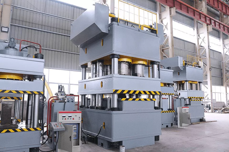
5.1. Press Frame
The major components of press frame like Bed, Top Head, Slide, Uprights shall be fabricated using ISO 2062 Grade 2 plates and by welding them as per standard welding procedures. The plates should be as per BIS specifications & Material Test Certificate (MTC) of the plates issued by steel plant should be submitted to inspecting officials of NFC. All critical welds shall be tested for weld defects. Method of testing weld defects and method of stress relieving shall be explained in the bid. The fabricated structure shall be duly stress relieved.
The records of stress relieving should be furnished during the inspection of the machine. The detailed design calculations for the suitability of the critical sections or the FEM analysis should be furnished after placement of order. A cross sectional schematic diagram for major assemblies shall be furnished in the bid to indicate the constructional features. The slide should have 8 point guiding with in-situ adjustable & replaceable Ph. Bronze liners for long life.
Note: The frame of the hydraulic press shall have openings from all four sides such that the pressing area is accessible from all four sides. Minimum 1000 x 1500mm for sides opening and 1500 x 1500mm for front and back openings(W x H)Noise levels shall not exceed 85 dB, when measured at a distance of 1 meter from the machine in the free field conditions.
5.2. Main Ram and Cylinder
Main ram of the press shall be made of forged block. The main cylinder shall be forged out of single block and then machined. Relavant certificates for ram and cylinder shall be provided during PDI.
5.3. Die and Punch Assembly
a) Die assembly with cavity height of 430mm shall be provided for 150mm and 180mm diameter compacts.
b) For rectangular compacts, the punch shall be 50 mm wide and 500 mm long. The cavity shall be 400 mm deep(approx.)
c) The gap between bottom of punch and the top surface of die shall be 320mm.
d) Ram shall be chrome plated and surface finish certificate shall be provided.Chrome plating thickness shall be clearly indicated in the offer.
e) Moving bed of the press and die inner liner etc. shall be forged Components
Note: Die and punch for all three type of compacts is in the scope of bidder. Die liner has to be sink fitted in the die housing.
Details of die and punch shall be discussed during detailed engineering and the approved drawings shall be used for manufacturing.
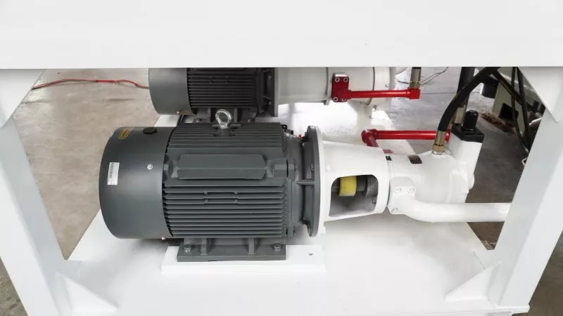
5.4. Hydraulic System
Positive displacement hydraulic pumps shall be provided for the hydraulic system of the press. Oil flow shall be pulsation free. Detailed hydraulic circuit shall be provided along with the bid. Number of pumps provided, their type, make, model no. And capacity shall be clearly indicated in the bid.
The tank(s) of hydraulic system shall be as per the latest applicable standard. It shall be provided with an air breather(s), suitable baffle plates, filler breather, temperature indicator gauge, oil level gauge, inspection cover(s), provisions for addition of lines in future, over flow and drainage connections.
The maximum temperature of hydraulic oil should not exceed 55 deg.C during operation.
Hydraulic Power pack shall be installed on ground
The return line filter shall have clogging indicator. Type, make and model no. of each filter element shall be indicated in the bid. Cold bent, solid drawn, seamless steel tubes should confirm to DIN 2391/C, used in the hydraulic circuit. The hydraulic system shall be provided with ports for measuring pressure during troubleshooting or maintenance. Four sets of minimess couplings with pressure gauges shall be provided, which are used for measuring pressure at various points in the hydraulic circuit.
The hydraulic system shall include/incorporate an online oil filtration unit mounted on mobile trolley. The filtration unit should employ twin filters with provision for continuous measurement & display of oil cleanliness level in NAS & ISO scale and water percentage. This mobile filtration unit shall take oil from the main oil tank of the press, filter it & pump it back to the main oil tank. The filtration unit shall be of adequate capacity to handle the volume of oil in the main tank and shall be suitable for continuous operation.
6. Instrumentation & Controls
6.1 Machine shall have a PLC & HMI based Control System.
6.2 Specifications of PLC system:
a. Programming Package: Programming package for editing control logic shall be in scope of supply.
b. Controller: shall have at least two communication ports, one to be utilized for programming and another for networking.
c. All input and output modules utilized shall have optical isolation and have control voltage of 24 V DC only.
d. Rack power supply shall be of the type as recommended by PLC manufacturer.
e. All the outputs shall drive final control elements like solenoids, contactors etc through interpose relay modules.
f. Control supply to final control elements shall be through connectors with fuse and fuse blown indication.
g. CPU and memory loading shall not be more than 50%.
h. CPU supply shall not be utilized for interrogation supply of the inputs, for which separate supply shall be provided.
i. At least 30% inputs and 30% outputs of I/O modules shall be left unused/spare.
j. All the cables required for operation of press shall be in scope of supply of vendor. Cables for integrating all sensors with PLC shall be shielded type.
k. I/O cards shall be fully wired and brought to terminals both in case of used and unused.
l. Communication: all the control system components, like Controller, HMI and Electronic Drives (if any) shall be networked on digital communication
6.3 Specifications of Electronic Drives System (if any):
a. All the drives shall be sized to have minimum 20% higher rated current than that of respective motors.
b. These drives shall be networked with HMI and all critical parameters like speed, current etc. shall be displayed on HMI.
c. All the drives wherever used shall have sufficiently rated input chokes.
d. Drives selected shall have all latest control modes.
e. Configuration/Commissioning software for Drives and related specialized connecting cables/adapts for connecting drives with Computer shall be in scope of supply.
f. If any proprietary control card is utilized detailed diagnostic manuals/circuits with necessary test points shall be supplied.
6.4 Functions:
i. The control system shall be programmed for press specific operations like automatic, manual & maintenance modes.
ii. The control system shall have all required recipes for automatic pressure control based on different compact sizes.
iii. All important process parameters like pressure, compaction diameter, oil temperature etc. shall be logged and displayed in trend form.
iv. Facility of report generation of logged process data along with operator/shift in charge details, lot numbers, number of compactions etc. along with time stamp shall be available. It should be possible to print reports into a pen drive in pdf and csv formats. Also, necessary functions for transporting recorded data to central computer shall be available in chosen HMI as explained below.
6.5 Sensors: Electronic sensors shall be used for measurement of process parameters like pressure, oil level and temperature etc. and integrated with PLC system.
6.6 Provision for Networking: A communication port in control system shall be made
available to integrate the control system with centralized computer, and depicting all process status in that.
It is Proposed to Have Separate Alloying Addition System with Separate bins and weight monitoring system so that alloys can be filled in to the die cavity at suitable time and position. Similarly for metal sponge addition, separate drum lifting and feeding system to feed metal sponge into the die will be envisaged. It may be noted that these systems are not the part of hydraulic press. However vendors are encouraged to give there offer separately. The control systems envisaged for the press shall be able to configure and integrate these alloy and sponge addition system.