


Understanding CNC Press Brake Machine Axes
In this article, I will explore the fascinating world of CNC Press Brake Machine Axes. Understanding these axes is crucial for optimizing the performance and precision of your press brake operations. From the X and Y axes that control movement to the Z axis responsible for depth, each plays a vital role in achieving accurate bends. As I delve into the intricacies of these axes, you’ll gain insights that can help enhance your workflow and improve your overall production efficiency. Join me as we unravel the complexities of CNC technology!
Overview
When we say CNC press brake machine axes, we always heard of Y, X, R axis, but we are often into confusion with these axes. Because different axis means different moving direction, Today we will make a deep clear explanation about press brake axis.
A CNC press brake machine is used in metalworking to bend and shape metal sheets into a desired form. The machine typically has multiple axes that can be controlled by a computer numerical control (CNC) system, which allows for precise and repeatable bending operations.
Here are the most common CNC press brake machine axes found in press brake machines:
● X-axis: The X-axis controls the horizontal movement of the back gauge, which is the device that positions the metal sheet for bending.
● Y-axis: The Y-axis controls the vertical movement of the ram, which is the device that applies the bending force to the metal sheet.
● Z-axis: The Z-axis controls the depth of penetration of the ram into the die, which determines the angle of the bend.
● R-axis: The R-axis controls the horizontal movement of the bending die, which can be used to create bends with varying radii.
● V-axis: The V-axis controls the rotation of the bending die, which can be used to create complex bends and shapes.
Overall, the various axes in a press brake machine work together to create precise and efficient bending operations, making it an essential tool in metalworking industries.
CNC Press Brake machine Axes Explanation

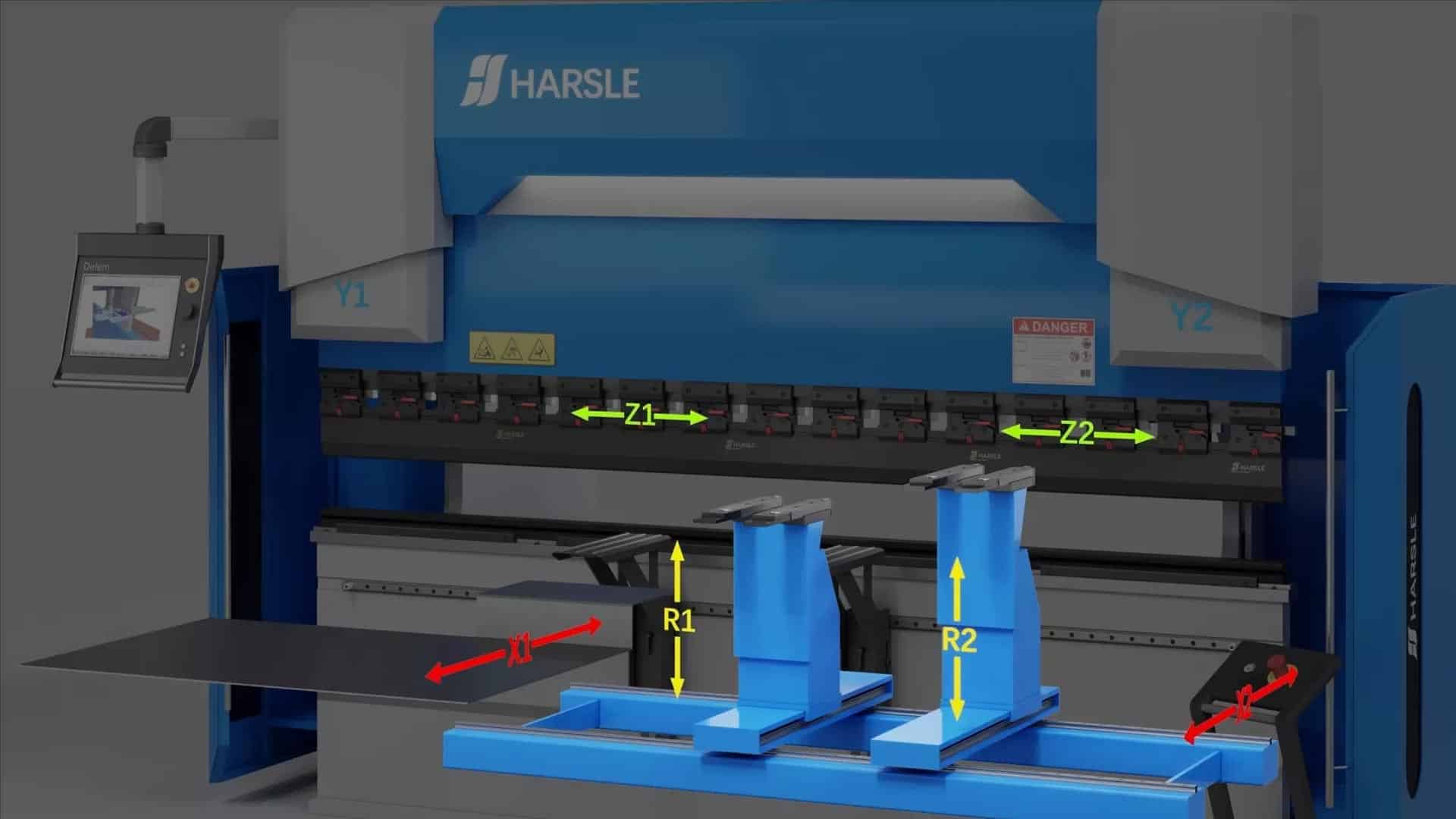
| Axis | Description |
| Y1 | left cylinder full closed-loop control axis |
| Y2 | right cylinder full closed-loop control axis |
| X1 | left stop finger back and forth moving axis |
| X2 | right stop finger back and forth moving axis |
| R1 | left stop finger up and down moving axis |
| R2 | right stop finger up and down moving axis |
| Z1 | left stop finger left and right moving axis |
| Z2 | right stop finger left and right moving axis |
| V | crowning axis |
BACKGAUGE
| No. | Name | Description |
| 1 | BG-1 | X |
| 2 | BG-2 | X, R |
| 3 | BG-4 | X, R, Z1, Z2 |
| 4 | BG-5 | X, X1, R, Z1, Z2 |
| 5 | BG-6 | X1, X2, R1, R2, Z1, Z2 |

How to choose the CNC press brake machine axes.
Selecting the right backgauge axis for a press brake is crucial for achieving accurate and efficient bending operations. Here are some factors to consider when choosing a press brake backgauge axis:
Determine Bending Complexity:
Assess the complexity of your bending tasks. For simple bends on a single plane, a press brake with a single-axis backgauge might suffice. However, if your applications involve multiple bends, varying angles, or different planes, you’ll need a press brake with multi-axis capabilities.
Material Specifications:
Consider the type and thickness of materials you’ll be working with. Thicker and harder materials require more tonnage, so choose a press brake with sufficient capacity. Additionally, the length of the material influences the size of the press brake you need.
Precision and Accuracy:
Determine the level of precision your applications demand. For high-precision bending, especially when dealing with intricate designs or tight tolerances, a press brake with advanced CNC controls and high-resolution backgauge systems is essential.
Backgauge Requirements:
Evaluate the need for a backgauge system. A backgauge assists in positioning the material accurately, enabling consistent bends. Choose the appropriate number of backgauge axes based on the complexity of your bends. Common configurations include X, R, Z1, and Z2 axes.
Tooling Considerations:
Check the compatibility of the press brake with the tooling you plan to use. Different tool setups may require specific press brake models or modifications.
Automation and Software:
Consider the level of automation required. Modern press brakes often come with advanced software and CNC controls for easy programming and automation. Automation not only improves efficiency but also reduces the chance of errors.
Space and Layout:
Evaluate the available space in your workshop. Press brakes come in various sizes, so choose a machine that fits comfortably in your workspace while allowing easy material handling.