


When it comes to efficient metal processing, understanding punching machine work is crucial. If you’re wondering how punching machines operate and why they are essential for manufacturing, you’re in the right place. In this article, I’ll explain how punching machines function, their setup process, and the key reasons why they are indispensable for metal fabrication. Whether you’re exploring automation or aiming to improve production quality, this guide will give you the practical insights you need.
How Does a Punching Machine Work?
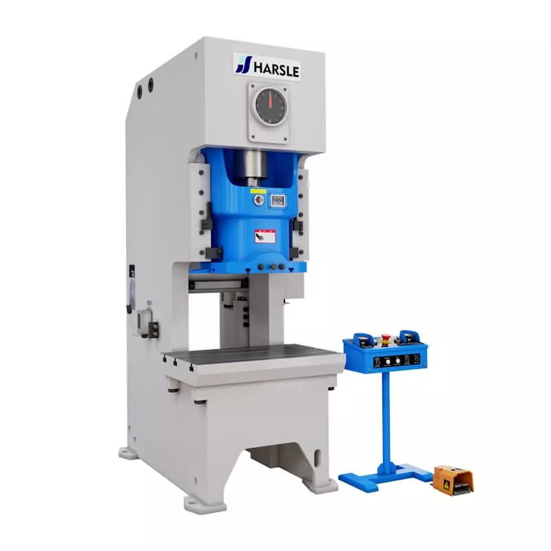
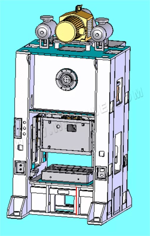
A punching machine operates by applying a controlled force to a punch and die assembly, creating holes or shapes in sheet metal or other materials. The punch presses down on the material with significant force, shearing it against the die to form a clean, precise cut. Modern punching machines often use hydraulic, mechanical, or CNC systems for enhanced speed and accuracy. Understanding the punching machine work process is essential for achieving high-quality results with minimal waste.
Punching Machine Features
⒈User-friendly operation interface, only need to input the hole coordinate parameters of the product to process the product without programming;
⒉The numerical control screen operation interface is more intuitive and convenient;
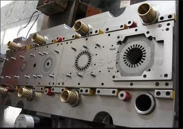
⒊Wide processing range: can process a variety of holes of various specifications and shapes by changing the mold;
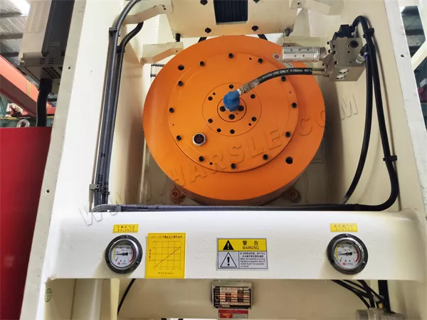
⒋Pneumatic feeding, hydraulic punching, stable operation;
⒌The machine can process up to an unlimited number of holes continuously, and the processed holes are free of burrs, which are simple and beautiful;
⒍The machine tool is easy to adjust and the mold change is quick, which can greatly save the adjustment time;
⒎The consistency of automated processing products is good and the product quality is more stable.
Punching Machine Scope:
1. Power sector 10KV distribution network cross-arm, iron tower reaming, hole repair, opening; power plant, substation, copper and aluminum busbar, equipment line clamp, flat steel, and other openings.
2. Inspection and reinforcement of the railway, post and telecommunications, petroleum, geological and construction industries. Because the machine does not require electric energy, it is especially suitable for field, high altitude, and underwater operations.
Punching Machine Notes:
1. Check whether the punch and die are matched before the operation, otherwise, the host will be damaged.
2. Before punching, the die must be screwed tightly.
3. If abnormal faults are found during operation, the punching should be stopped and the fault should be eliminated to avoid damage to the machine.
4. The screw and the nut should be lubricated with oil.
The Working Principle of the Punching Machine:
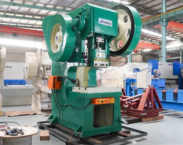
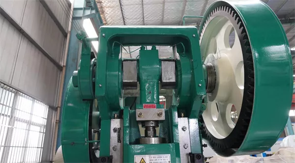
Its working principle is that the engine drives the inertia wheel to continue to operate. When it is not activated, the inertia wheel will continue to store energy through the spring. When the sole is stepped on the pedal, the energy stored by the inertia wheel will follow the transmission guide. When the rod is transferred to the drill bit, a punch is punched on the object.
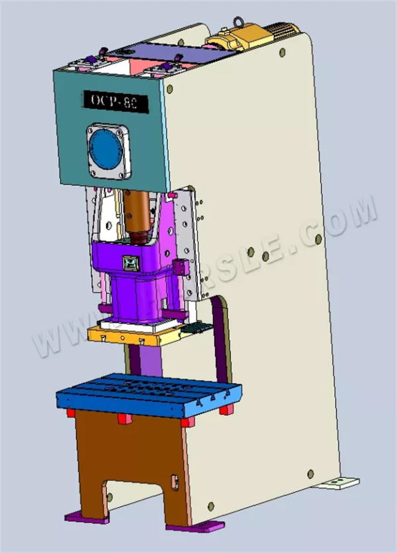
Punching Machine Classification:
It is now mainly divided into CNC and hydraulic punching machines. The first type is mainly used for punching processing of some softer products such as leather, plastic, PVC, paper, etc. The second type is generally used for punching holes in metal sheets such as copper sheets, steel sheets, and angle irons. It is especially suitable for some operations in the power and construction industries.
Note On the Punching Machine:
Punching machines are generally suitable for processing some soft materials, and the gravity is used to make the drill bit punch down when processing; so we should pay attention to the appropriate lifting force, otherwise it will cause cracks in the processing material. Do not look down during the operation to prevent the waste from damaging the eyes, and do not put your hands in the scope of the stamping, and ensure that there are no other unrelated workers in the danger range.
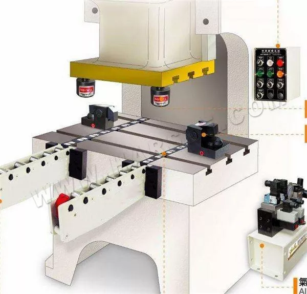
Introduction of Punching Machine Structure
There are various types of punching machines, but due to the different structural principles, the price and processing effects will also change accordingly. Of course, even for different types of presses, there is always a commonality in the composition of the structure. This article introduces some common structures and parts of presses, and elaborates on their characteristics and parts to help you better understand and use the presses.
●Brief Structure
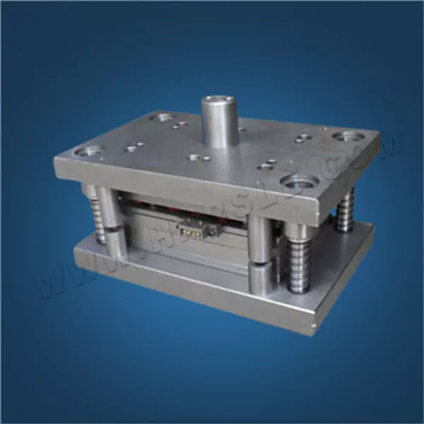
Upper mold: The upper mold is the upper part of the whole punching mold, i.e. the part of the punching mold installed on the press slide.
Upper mold holder: The upper mold holder is the uppermost plate part of the upper mold, which is close to the press slide when working and fixed to the press slide by the mold handle or directly.
Lower mold: The lower mold is the lower part of the whole mold, i.e. the part of the mold mounted on the press table.
Lower mold holder: The lower mold holder is the plate part of the bottom surface of the lower mold, which is fixed directly to the press table or to the pad during work.
Edge wall: The edge wall is the side wall of the edge of the mold hole for punching.
Edge slope: The edge slope is the slope of each side of the edge wall of the blanking mold hole.
Air cushion: The air cushion is a pop-up device powered by compressed air.
Reverse side pressure block: The reverse side pressure block is the part that supports the one-way force convex mold from the other side of the working surface.
Guide sleeve: guide sleeve is a tubular part that provides precise guidance for relative movement of upper and lower mold holders, mostly fixed in the upper mold holder and used in conjunction with the guide pillar fixed in the lower mold holder.
Guide plate: The guide plate is a plate with a precise sliding hole in the convex mold, used to ensure the mutual alignment of the convex mold and the concave mold, and to unload the material (pieces).
Guide pillar: guide pillar is a cylindrical part that provides precise guidance for relative movement of upper and lower mold holders, mostly fixed in the lower mold holder and used in conjunction with the guide sleeve fixed in the upper mold holder.
Guide pin: guide pin is a pin-shaped part that extends into the material hole to guide its position in the concave mold.
Guide plate mold: Guide plate is a mold that is guided by a guide plate, and the convex mold is not separated from the guide plate when the mold is used.
Guide plate: The guide plate is a plate shaped guiding part to guide the strip (strip, roll) material into the concave mold.

Guide pillar mold holder: The guide pillar mold holder is the mold holder where the guide pillar and guide sleeve slide against each other.
Punching mold: Punching mold is process equipment installed on the press for production of punched parts, and consists of two parts, upper and lower, which fit each other.
Convex mold: The convex mold is a convex part of the mold that directly forms the punched part, i.e., the part with the shape of the working surface.
Concave mold: The concave mold is a concave part of the mold that directly forms the punched part, i.e., the part with the inner shape of the working surface.
Protective plate: The protective plate is a plate part that prevents fingers or foreign objects from entering the dangerous area of death.
Pressing plate (circle): Pressing plate (circle) is a part of the mold used to hold down the stamping material or process parts to control the flow of material. In the deep-drawing mold, most of the pressing plates are called pressing circle.

Crimping tendon: Crimping tendon is a tendon-like protrusion used to control the material flow in the drawing mold or deep drawing mold, which can be a partial structure of the mold or crimping ring or a separate part set into the mold or crimping ring.
Pressed material threshold: pressed material threshold is the special name of the pressed material bar with rectangular cross section. See “pressure material tendon”.
Material carrier plate: Material carrier plate is a plate part used to extend the upper plane of the concave mold to support the pressed material.
Continuous mold: A continuous mold is a mold with two or more stations where the material is fed into one station at a time with the press stroke so that the punched part is gradually formed.
Side edge: The side edge is a convex mold that cuts a feeding position notch in the side of the strip (strip, coil) material.
Side pressure plate: The side pressure plate is a plate part that exerts pressure on one side of the strip (strip, coil) material by means of a spring to make the other side close to the guide plate.

Top bar: The top bar is a rod-shaped part that directly or indirectly ejects the work (sequence) or scraps with upward action.
Top plate: The top plate is a plate part that moves in the concave mold or module to eject work (sequence) or scrap directly or indirectly by upward action.
Ring: The ring is a ring-shaped protrusion of teeth on the fine blanking mold or press plate with teeth, and is a partial structure of the mold or press plate with teeth rather than a separate part.
Limit sleeve: The limit sleeve is a tubular part used to limit the minimum closing height of the mold, and is usually set outside the guide pillar.
Limit column: Limit column is a column-shaped part to limit the minimum closing height of the mold.
Positioning pin (plate): Positioning pin (plate) is a part that ensures the constant position of the process parts in the mold, and is called positioning pin or positioning plate by its different shapes.
Fixed plate: Fixed plate is a plate part to fix the convex mold.
Fixed unloader plate: Fixed unloader plate is the unloader plate fixed on the mold in an immovable position.
Fixed stopper pin (plate): Fixed stopper pin (plate) is a stopper pin (plate) that is fixed in the mold.
Unloader: The unloader is a non-plate part or device that removes the work (sequence) from the outer surface of the mold.
Unloader plate: The unloader plate is a fixed or movable plate-shaped part that removes material or work pieces from the mold. The Unloading plate is sometimes made into one with the guide plate, and also plays the role of material guide, still called unloading plate.
Unloading screw: unloading screw is a screw fixed on the pop-up unloading plate, used to limit the static position of the pop-up unloading plate.
Single process mold: Single process molds is a mold that completes only one process in one stroke of the press.
Scrap cutter: There are two kinds of scrap cutters:
1. cutter installed on the flange cutting edge mold for cutting off the whole circle of cutting edge scrap to facilitate removal;
2. cutter installed on the press or mold for cutting off the strip (strip, roll) scrap according to the fixed length to facilitate removal.
Combination punching mold: Combination punching mold is a general and adjustable set of punching molds that form various punching parts step by step according to geometric elements (straight line, angle, arc, hole). The outline of a flat punching part generally requires several sets of combination molds to be punched in stages.
The starting stopper pin (plate): The starting stopper pin (plate) is a part for positioning when feeding the starting end of the material. The starting stop pins (plates) are mobile.
Piece: Piece is a complete concave mold, convex mold, unloading plate or fixed plate, etc.
Block (plate): block (plate) is for the side edge of the notched material feeding the hardened parts for positioning, and used to balance the side edge of the one-sided cutting force. Block (plate) is generally used in conjunction with the side edge.
Stopper pin (plate): stopper pin (plate) is the material along the feeding direction of the positioning parts, to its different shape and called stopper pin or stopper plate. The stopper pin (plate) is the collective name of fixed stopper pin (plate), movable stopper pin (plate), starting stopper pin (plate), etc.
Pad: Pad is a hardened plate part between the fixed plate (or concave mold) and the mold base, to reduce the unit compressive stress of the mold base.
● Detailed Structure
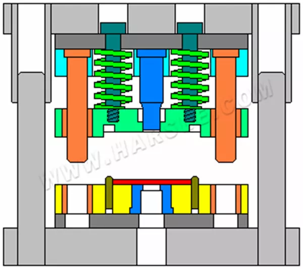
The mold on the press is the upper part of the mold, i.e. the part of the mold mounted on the press slide. The lower mold is the lower part of the mold, i.e. the part of the mold mounted on the press table. The lower mold holder is the plate part on the bottom side of the lower mold. The edge wall is the side wall of the punching mold hole edge. The slope of the edge is the slope of each side of the mold wall. The air cushion is a pop-up device powered by compressed air. The counter press is a part that supports the one-way stressed mold from the other side of the working surface.
The punching guide is a tubular component designed to ensure the precise alignment of the upper and lower mold holders during operation. It is typically fixed to the upper mold holder and works together with a guide pillar that is mounted on the lower mold holder. Meanwhile, the guide pin is a pin-shaped part inserted into the material’s hole to accurately position it within the concave mold, ensuring correct placement during the punching process.
The guide plate, on the other hand, serves as a plate-shaped component that directs strip or rolled material into the concave mold. In a guide plate mold, the convex mold remains attached to the guide plate during use, maintaining alignment throughout the operation. Additionally, the guide post mold holder refers to the type of mold holder where the guide post and guide sleeve slide against each other to facilitate smooth and precise movement.
A punching mold is a process tool installed on a press machine to produce punched parts. It consists of two matching sections: the upper and lower molds. The convex mold is the raised portion that directly shapes the punched part, while the concave mold is the recessed portion that complements it, also contributing to the final form of the part. To ensure safety during operation, a protective plate is installed to prevent fingers or foreign objects from entering the hazardous area around the mold.
The press bar is a rib-like protrusion found in drawing or deep drawing molds, designed to control the material flow during forming. It can be an integrated part of the concave mold or the press ring. When the press bar has a rectangular cross-section, it is specifically referred to as a pressing sill. Additionally, a supporting plate is used to extend the upper surface of the mold, providing extra support for the material being pressed.
The side edge of the press is a convex mold designed to cut a positioning notch along the side of the strip or coil material, helping to ensure proper alignment during processing. The side pressure plate uses a spring mechanism to apply pressure on one side of the strip or coil, forcing the opposite side tightly against the guide plate for accurate positioning. The top bar is a rod-shaped component that directly or indirectly pushes the workpiece or scrap material upward to facilitate removal from the mold.
The top plate operates within the mold or module, moving upward to eject the workpiece or scrap either directly or indirectly. The limit sleeve is a tubular component used to restrict the mold’s minimum closing height, preventing over-compression. Similarly, the limit post is a post-shaped part that also defines and maintains the minimum closing height during the mold’s operation, ensuring consistent and safe performance.
Punch fixing plates is a plate that holds the mold. Fixed unloading plate is a plate that is fixed to the mold in an immovable position. The fixed stopper pin (plate) is a stopper pin that is fixed in the mold. Unloader is a non-plate part or device that removes the workpiece from the outer surface of the mold. The unloading screw is a screw that is fixed to the pop-up unloading plate.

Single process mold is a mold that completes only one process in one stroke of the press. There are two types of scrap cutters. Combination molds are universal, adjustable sets of molds that form various punching parts step by step according to geometric elements (straight line, angle, arc, hole). The outline of a flat punching part generally requires several sets of combination molds to be punched in stages. The starting stopper pin (plate) is a part for positioning when feeding the starting end of the material. Block is a complete concave mold, convex mold, unloading plate or fixed plate, etc. The block (plate) is generally used in conjunction with the side edge.
Conclusion
Understanding punching machine work is vital to unlocking faster, more efficient production in metal fabrication. By mastering the setup, operation, and maintenance of your punching machine, you can maximize productivity while minimizing downtime and waste. If you’re ready to explore high-performance punching solutions or need expert advice on selecting the right machine for your factory, feel free to contact our HARSLE team for personalized support.


