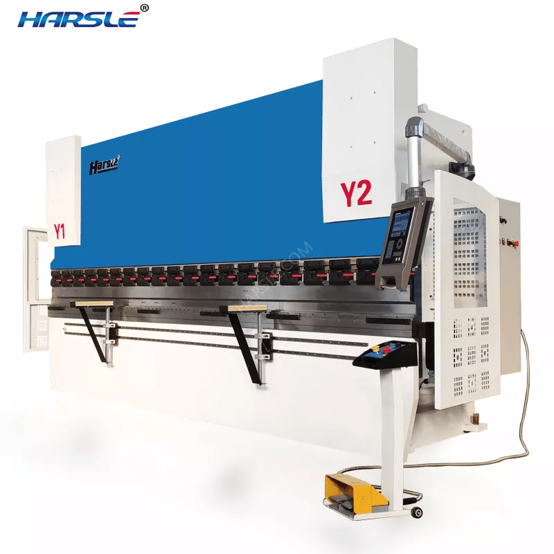
Effective Bending Machine Operation and Troubleshooting Tips

In my experience working with bending machines, I’ve learned that understanding both operation and troubleshooting is crucial for achieving optimal results. Proper operation techniques ensure that bends are precise and consistent, while effective troubleshooting skills help address common issues that may arise during the bending process. Over the years, I have encountered various challenges and have developed strategies to resolve them quickly. In this article, I will share my insights on bending machine operation and machine troubleshooting, providing valuable tips that can assist both novice and experienced operators in maintaining efficiency and quality in their work.
First, the Adjustment of the Bending Machine

1. Adjust the upper limit of the slider
Adjusting the position of the slider allows the rising slider to stay at the desired top dead center position, which reduces the stroke distance of the slider and reduces the duty cycle time, thereby increasing productivity.
2. Adjusting the slider slow motion
When the slider goes down, the slider “I” touches the stroke switch to make the slider perform slow motion, and the length of the slow stroke time is adjusted by the adjustable potentiometer.
(1) Upper and lower die clearance adjustment (slider must stop at top dead center)
A. Operate the button on the button box at the bottom right of the workbench and operate according to the direction indicated by the sign. The initial adjustment gap should be larger than the thickness of the plate, and the gap should be trimmed according to the angle of the folded workpiece. It can also be fine-tuned with the handwheel. The adjustment value is displayed by the calculator. Each digit is increased by one millimeter (0.1 mm/rev).
B. If the workpiece angles are inconsistent at both ends, loosen the nails, move the connecting rod to the left, disengage the left and right rotating connections, and turn the handwheel (up or down) to change the distance of the mechanical limit of one end to achieve fine adjustment of the workpiece. The purpose of the end angle.
C. If the workpiece angles are consistent at both ends, the intermediate angles (large or small) are inconsistent, which can fine-tune the upper mold. When fine-tuning, close the upper mold to the lower mold slot, and slightly loosen the screws on the template and the adjustment block on the middle section. (The above model does not fall as a principle) Then adjust the diagonal block on the upper part of the middle section (slightly left or right). In a place with a small intermediate angle, make the upper mold bulge in an appropriate amount, tighten the nails, and try to fold until the full-length angle of the workpiece reaches the allowable value.
3. Bending machine bending force adjustment
Calculate the kinematic value of the bending force of the sheet according to the calculation formula of the bending force, and calculate the indicated pressure P value according to the table, and then adjust the hand wheel of the relief valve 8 so that the force generated is slightly larger than the folding plate. The value of a thousand cows can be.
4. Adjustment of the backgauge distance
The bending machine back gauge is used for positioning in the longitudinal direction when bending the sheet. The button on the front button box controls the motor to adjust, and the adjustment value can be read from the number of revolutions on the button box. The converted value of the number of revolutions is 0.1 mm / rev, and hand wheel for fine adjustment.
5. The foot switch can make the slider move up or down, and the operation is light.
Second, the Test and Operation of the Bending Machine
1.Before the test, you must add calcium-based grease to each lubrication point (see Lubrication Signage). Add 46# hydraulic oil to the fuel tank of the hydraulic system. After the first time, replace it with one month, and then change the oil according to the specific conditions every year. The oil temperature is less than 15 °C.
2.When the bending machine first test is started, the oil pump motor unit is started to run empty, and then the “jog” is used to test the machine’s action; then the “single” and “continuous” actions and the performance of the slider stroke and the backgauge control are tested. The following steps can only be performed when the operation is normal.
Calculate or check the bending machine bending force and the opening size of the V-groove of the lower die according to the thickness of the sheet and the length of the flap (the die size should generally be greater than or equal to 8 times the thickness of the panel).
2. Align the upper and lower mold centers.
3. Determine the gap between the upper and lower molds and adjust them.
4. Determine the position of the front and rear stops.
5. Determine the action specification “jog”, “single” or “continuous” and select by the transfer switch.
6. Place the workpiece in the middle of the machine table to test pressure.
7. Adjust the mold gap again and adjust the upper mold clamp if necessary.
8. Pay attention to the sealing of each seal and find that the seal is replaced in time.
9. Sheet bending should be in the middle of the bending machine. It should not be biased or unilateral load, so as not to affect the accuracy of the workpiece and the machine. If some workpieces need to work on one side, the load should be less than 100KN, but should be as close as possible to both sides. At the same time, fold the plate to solve the problem of unilateral eccentricity.
10. When the length of the folding plate is less than 600mm, it is not allowed to do the full-load (1000) folding work (the folding load does not exceed 100KN per 100mm).
11. Pay attention to the motor turning (counterclockwise) when testing the car.
Third, the Machine Repair, Maintenance and Troubleshooting
Anyone who operates and repairs this bending machine must read this instruction carefully, carefully understand and familiarize with the main structure, performance and usage of the machine according to the machine entity, do regular maintenance work, and make daily use records for easy reference.
1. The machine must be specially staffed. The operator should be familiar with and properly use the machine’s operating procedures and check the workpiece bending machine force.
2. Keep the cleanliness of the oil and the smooth flow of the oil, so as to avoid the oil pump sucking up, causing the pipe to vibrate, or causing the pipe to burst and leak, while avoiding the jamming and scratching of the hydraulic components.
3. This machine is made of dispersive lubrication. In use, it should be refueled according to the working condition of the machine and refer to the lubrication point indication diagram of the machine (the left side panel of the machine is equipped with a lubrication nameplate).
4. The bending force of the workpiece is not allowed to be greater than the nominal force.
5. Do not work on one side and single point load.
6. Electrical and hydraulic components must be flexible and positionally correct.
7. According to the thickness of the bent sheet material, the gap between the upper and lower molds is initially adjusted, and the gap can be adjusted by about 1 mm larger than the thickness of the plate, but it must be larger than the thickness of the plate, so as not to be crushed by the gap. Mold.
8. The user must always have spare parts that are included with this bending machine.
9. When an abnormality or noise is found, it must be stopped immediately to find out the cause for maintenance.
The failure of the hydraulic system of the bending machine includes: the valve cannot be reversed or the reversing action is slow, the leakage, the electromagnetic pilot valve is faulty, and the like.
(1) The reversing valve cannot be reversed or the reversing action is slow, generally caused by poor lubrication, spring jamming or damage, oil stains or impurities jamming the sliding part. In this regard, first check whether the oil mister is working properly; whether the viscosity of the lubricating oil is appropriate. If necessary, replace the oil, clean the sliding part of the reversing valve, or replace the spring and the reversing valve.
(2) After long-term use, the reversing valve is prone to wear of the valve core seal, damage to the valve stem and the valve seat, resulting in leakage inside the valve, slow valve operation or failure to normal commutation. In this case, replace the seal, stem and seat, or replace the reversing valve.
(3) If the inlet and exhaust holes of the electromagnetic pilot valve are blocked by oil and other debris, the sealing is not strict, the movable iron core is stuck, the circuit is faulty, etc., and the reversing valve can’t be normally reversed. For the first three cases, the sludge and impurities on the pilot valve and the moving iron core should be cleaned. Circuit faults are generally divided into two types: control circuit faults and electromagnetic coil faults. Before checking the circuit fault, first turn the manual knob of the reversing valve a few times to see if the reversing valve can be normally reversed under the rated air pressure. If the commutation is normal, the circuit is faulty. During the inspection, the voltage of the electromagnetic coil can be measured by the meter to see if the rated voltage is reached. If the voltage is too low, the power supply in the control circuit and the associated stroke switch circuit should be further checked. If the reversing valve cannot be reversed normally at the rated voltage, check the connector (plug) of the solenoid for looseness or contact. The method is to unplug the plug and measure the resistance of the coil. If the resistance is too large or too small, the solenoid is damaged and should be replaced.


