


Sheet Follower: Essential for Press Brakes
As someone who has worked extensively with press brakes, I can confidently say that a sheet follower is essential for press brakes. This invaluable tool not only enhances the efficiency of the bending process but also ensures precision and safety. In this article, I will share my insights on the benefits of using sheet followers, how they improve workflow, and why they are a must-have for any operation involving press brakes. Whether you’re a seasoned operator or just starting out, understanding the role of sheet followers can significantly impact your production quality.
What is a Sheet Follower?
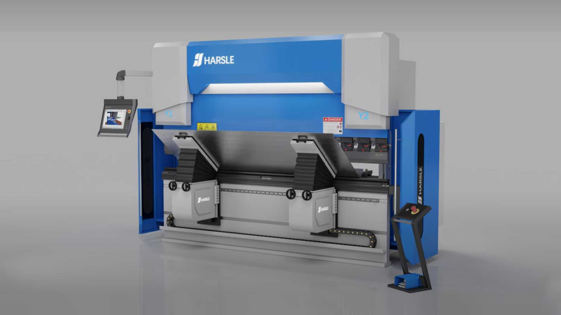
A sheet follower is an automated support system designed to assist in the handling of large or heavy sheet metal during the bending process. It is primarily used in CNC press brakes to support the sheet metal as it moves through the machine, preventing it from sagging or shifting.
The sheet follower operates alongside the press brake, typically following the contour of the metal sheet, providing support while ensuring that the sheet maintains proper alignment during bending. This is especially important when working with longer or thicker sheets, which might otherwise be difficult to manage manually.
When a sheet of metal is bent using a press brake, a punch descends to deform the sheet around a die, creating the desired bend. The sheet follower, also known as a “pressure die” or “bottom die,” is positioned on the bed of the press brake and acts as a support surface for the sheet metal opposite the punch. It exerts upward pressure on the sheet metal, holding it firmly against the bending die. This pressure prevents the sheet from springing back, wrinkling, or deforming as the bend is being formed.
The sheet follower ensures that the sheet metal maintains contact with the bending die throughout the bending process, resulting in accurate and high-quality bends. It is an essential component in achieving precise bends in sheet metal fabrication using a press brake. Different types of sheet followers can be used based on the specific bending requirements and the design of the press brake.
Why is a Sheet Follower Essential for Press Brakes?
- Improved Precision and ConsistencyOne of the most significant benefits of a sheet follower is its ability to maintain consistent alignment of the sheet throughout the bending process. This minimizes the chances of distortion or misalignment, which can lead to errors in the final product. As a result, manufacturers can achieve high levels of precision with each bend, ensuring that every part meets exact specifications.
- Enhanced Efficiency and ProductivityHandling large, heavy sheets manually is time-consuming and labor-intensive. A sheet follower streamlines this process by automating the movement and support of the sheet, reducing the need for manual labor. This not only speeds up the bending process but also minimizes downtime, allowing for a higher throughput of parts.
- Increased SafetyIn the absence of a sheet follower, operators often need to physically handle large sheets, which can be hazardous, especially when working with heavy or awkwardly shaped materials. By using a sheet follower, operators can avoid direct contact with the sheet during the bending cycle, reducing the risk of injury and increasing overall safety in the workplace.
- Support for Larger BendsWhen working with large sheets of metal, especially those that are longer or thicker, keeping the material in place during bending becomes increasingly difficult. The sheet follower provides the necessary support to ensure that the metal stays properly aligned, allowing the press brake to make precise bends without the material shifting or warping.
- Reduced Scrap and Material WasteBecause the sheet follower helps maintain precise alignment, the chances of producing defective parts are greatly reduced. By ensuring accurate bends every time, manufacturers can cut down on material waste and scrap, leading to cost savings and more efficient use of raw materials.
America-Miami-Customer-Feeback-1.jpg)
Uzbekistan-Customer-Feedback1.png)
Kosovo-Customer-Feedback11.png)
Russia-Customer-Feedback.jpg)
Russia-Customer-Feedback-3.jpg)


