Sheet Metal Forming Technology-Manual Bending of Sheet Metal
In my hands-on experience with sheet metal forming technology, I have found that manual bending of sheet metal remains a fundamental skill in the industry. Despite the advancements in automated equipment, manual bending offers flexibility and precision that can be invaluable for smaller projects or intricate designs. Over the years, I have honed my techniques and learned the best practices for achieving accurate bends while maintaining the integrity of the material. In this article, I will share insights into sheet metal forming technology, focusing on the manual bending process, its techniques, and tips that can help both beginners and experienced fabricators excel in their work.
Manual Bending of Sheets
There are many bending processing methods for sheet metal. Manual bending refers to the processing of bending sheet metal parts using simple tools and manual operations, which mainly include the bending and hemming of thin sheets.
Manual bending is one of the important tasks of metal work, and many complex sheet metal parts need to be made by hand. Some common shapes of hand-bent parts are shown in the figure.
Manual bending of sheets is mainly used for thin sheets with a thickness of less than 3mm, especially for sheets with a thickness of 0.6~1.5mm. For the bending of thicker sheets, the processing method of locally heating the bending part and then bending is often used. The parts processed by sheet metal bending are generally small and medium-sized bending parts. In production, it is often used for the processing of closed or semi-closed parts that are difficult to form with a small number of single-piece machine tools.

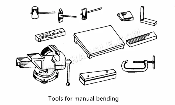
⒈Manual bending tool
Manual bending tools mainly include various types of hammers, wooden boards, horns, gauge irons, bench vices, bow clamps, etc.
⒉Calculation of the length of the curve blank
When the sheet is bent, the accuracy of the unfolded size of the bent part is directly related to the dimensional accuracy of the bent work piece. Since the bending neutral layer has the same length before and after the bending deformation, the length of the bending neutral layer is the unfolded length of the bending part blank. In this way, the key to the calculation of the blank length of the entire curved part is how to determine the radius of curvature of the curved neutral layer. In production, an empirical formula is generally used to determine the radius of curvature p of the neutral layer.
After the position of the neutral layer is determined, the sum of the length of the straight line and the arc part can be obtained, which is the length of the unfolded material of the best part. However, because the bending deformation is affected by many factors, such as material properties, mold structure, bending method, etc., for bending parts with complex shapes, more bending angles, and small dimensional tolerances, the above formulas should be used for preliminary calculations to determine the test. After bending the blank, the accurate blank length can be determined after the test bending is qualified.
● In the calculation and production of 90° bending parts, when the bending angle is 90°, the common deduction method is used to calculate the expansion length of the bending part, as shown in Figure 7-3. When the thickness of the sheet is t, the bending inner angle radius is r, and the bending part is blank Expand the length L to
L=a+b—u
In production, if the requirements for the length of the bending part are not accurate, the unfolded length L of the bending part can be approximated by the following formula (where a and b refer to the length of the two right-angle sides of the bend, and t is the thickness of the sheet).
When the bending radius r≤1.5t, L=a+b+0. 5t;
When the bending radius is 1.5t<rs≤5t, L=a+b;
When the bending radius is 5t<r10≤t, L=a+b-1.5t;
When the bending radius r>10t, L=a + b—3.5t.
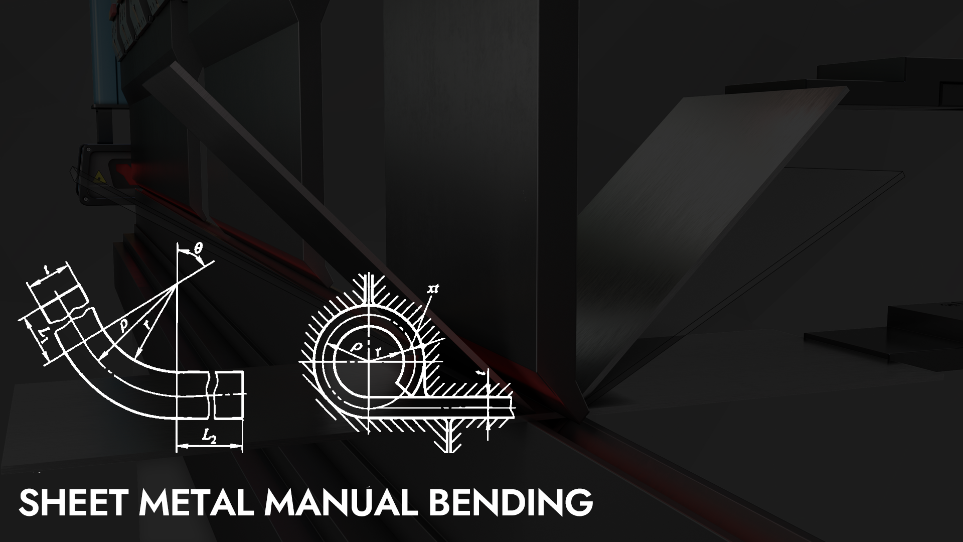
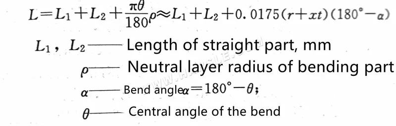
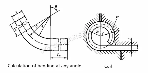
● Calculation of bending at any angle The bending part of any bending angle can be calculated by the following formula
For the dumpling chain bending piece with r=(0.6~3.5)t, when the rice is bent by the rolling die method shown in Figure (-4), the punch applies a pressing knife to one end of the blank, which is different from the general bending Due to the plastic deformation, the material is not thinner but thicker. The armor layer moves from the middle of the sheet thickness to the curved outer layer, so the displacement coefficient of the neutral layer is greater than or equal to 0.5.
● Bending of angles
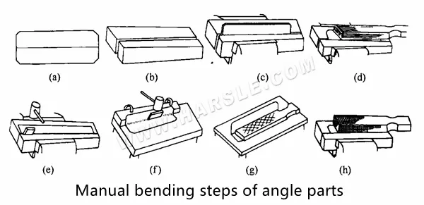
To manually bend an angle, first calculate the size and extension, then draw the bending centerline. Prepare two modules or iron pieces longer than the part, ensuring the R angle matches. Clamp the wool between these two sizes to align with the R center, using a rubber or wood plate as a mold. Employ wooden tools to evenly shape the R angle, tapping gently to stimulate and eliminate rebound. Align the part to 45° using a wood hammer, then smooth any recesses by placing the curved piece on a platform and tapping the inner surface with a rubber plate. Finally, tap the workpiece using a rubber plate to finalize the shape.
If the length of the workpiece is greater than the jaw length of 2 to 3 times, and the two sides of the workpiece are longer, when it is clamped on the platform, it can be pressed against the T-groove plate with the pressure plate, and below the bending pad. Wood strips, tap square wood, make it gradually bent into the desired angle.
When handmade, if the sheet T is thin (T ≤ 3mm) and the bend radius r ≤ 1.5t, the size accuracy of the bending member is not high, and the position of the bending centerline can be processed as follows:
a. Single-sided curved, its bending centerline is equal to the outer dimensions of the parts bending portion of the parts of the part of the thickness T, that is, H -T;
b. Double-sided curved, its bending midline is equal to the outer dimensions of the parts bending site to reduce the thickness, that is, A-2T. However, the expansion length L of the bending part should be determined following the relevant bad size calculation formula.
During the bending part, the bending is made after the hole is made, and when the size A and C are close to the size A and C should be made first, and the curved centerline should be placed, and then be positioned in the middle hole, and the curved fetal is sandwiched in the tiger. The pliers are bent on both sides. The force should be uniform and have the force of the pressing force when bending, so as not to pull the holes. Otherwise, to ensure the quality of the intermediate square, the processing method of the first bending and reworking the square hole should be taken.
During the bending part, the bending is made after the hole is made, and when the size A and C are close to the size A and C should be made first, and the curved centerline should be placed, and then be positioned in the middle hole, and the curved fetal is sandwiched in the tiger. The pliers are bent on both sides. The force should be uniform and have the force of the pressing force when bending, so as not to pull the holes. Otherwise, to ensure the quality of the intermediate square, the processing method of the first bending and reworking the square hole should be taken.
Sheet Metal Forming Technology-manual Bending of Sheet Metal
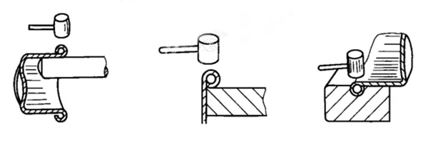
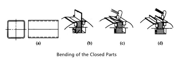
It is difficult to bend a single-piece small batch of sealed or semi-closed bending parts with a machine tool. In this case, manual bending is often used. When bending, first draw a bending line on the unfolded material, and then use a gauge iron to put it on the vise. When clamping, make the gauge iron 2~3mm higher than the backing plate, align the bending line with the angle of the gauge iron, and then use your hand Beat the curved side to bend both sides to a U shape. When bending, the force must be even, and there must be a downward separation, and finally, the mouth is upward to bend into a part.
Sheet Metal Bending
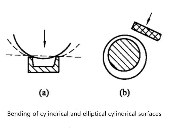
Common bending shapes of sheet metal mainly include cylindrical surface, elliptical cylindrical surface, and conical surface.
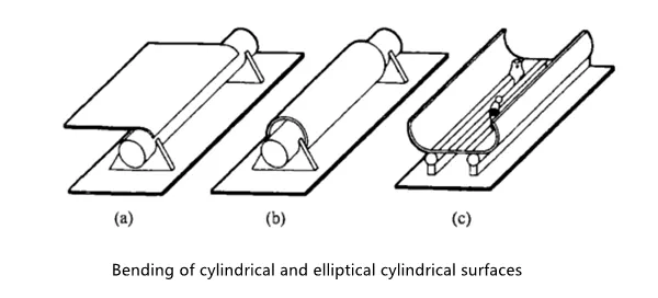
⒈Cylindrical surface and elliptical cylindrical surface bending The specific operation process of bending cylindrical surface and elliptical cylindrical surface includes several processes such as pre-bending, rounding, and rounding.
Before bending, a bisector parallel to the bending axis should be drawn on the sheet as a hammering reference for subsequent bending. Two parallel round steel or rails are used as bending molds for bending.
Regardless of whether the bending material is a thin plate or a thick plate, both ends should be pre-bent. When bending the ends on the round steel, the plate should be placed parallel to the round steel; for thin steel plates, wood or wood can be used. The hammer is hammered inwards gradually, when the joints overlap, a spot welding is applied, and the rounding is performed after welding. For thick plates, an arc hammer and a sledgehammer can be used to hammer between two round bars from both ends inward, and weld the joints after they are round, and then round.
Bending cylindrical and elliptical cylindrical surfaces, or hammer the billet on channel steel or I-beam, and then put it on a round bar with a slightly smaller diameter, and use a wooden square ruler to adjust the circle.
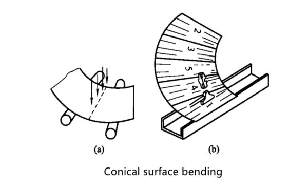
⒉To make a conical workpiece by bending the conical surface, you should first lay out the good material, and then draw the bisecting line of the conical surface on the sheet as a benchmark for hammering, and make a bending model. Because the curvature of the conical surface is inconsistent, so At least two card-shaped templates should be used for testing in proper positions.
When bending, first fix two round rods with the same diameter according to the equal division angle drawn by the fan-shaped blank. Place the slab on the rod and use an arc hammer and a sledgehammer to bend and hammer according to the plain line. First bend both ends, then bend the middle. And check with the template at any time, and finally set it on a round rod with a slightly smaller diameter for correction.
If it is formed on channel steel, it should be hammered in sections according to the sequence of 1, 2, 3…5 as shown in the figure and the direction of the ray. The hammering force should be increased from top to bottom, gradually increasing from light to light. After the radian and taper meet the requirements of the model, the bending of the next area can be carried out.
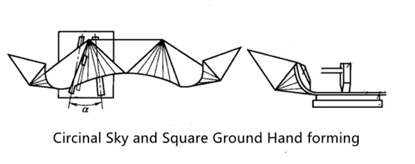
⒊The bending of sky-circle-shaped components. Because of the forming of the sky-circle, there are planes and arcs. The arc is not only a part of the oblique cone but also the one end of the cone is at the apex of the oblique cone. Its forming is generally done manually, transforming it into a polygonal pyramid, and forming it along its ridgeline as a bending line. Part of the curved surface in the sky circle becomes a polygonal surface. The curvature effect of the curved surface is positively related to the number of edges of the polygon.
Upper circle local components are often encountered in the production of steel structures. Since the number of applications is generally not large, manual forming is generally used. When forming, the curved surface adjacent to the edge must be formed first, and then the curved surface in the middle part is formed. Otherwise, when the curved surface of the end portion is formed, the edge portion is upturned due to the middle bending and occupying the operating space required for bending, which affects the normal progress of the forming work.
The operation of bending the upper circle local component is shown in the figure. The angle between the round bars of the lower die is α=10°~15°, and the diameter of the round bars is generally 25~35mm. When the bending hammer is pressed on the bending line with the type hammer, the hammering force should be uniform, and the hammering force should be changed from light to heavy with the different radius of curvature of each bending line. The arc part should be hammered lightly, and the square mouth part should be hammered heavily, and the arc should be continuously inspected with a shaped template.
For the bending of arc and angle joints, if the workpiece shown in the drawing is to be bent, the bending line should be drawn on the sheet. Before bending, the arcs and holes at both ends should be processed. When bending, clamp the sheet material in a bench vise with a gasket, first bend the two ends of parts 1 and 2, and finally bend the arc of the workpiece on the round steel.

Sheet Crimping
To increase the rigidity and strength of the edge of the part, the edge of the part is rolled over. This kind of work is called curling. There are two types of curling: wire curling and hollow curling.
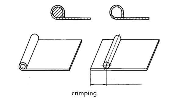
Wire crimping refers to inserting an iron wire inside the rolled edge to make the edge stronger. The thickness of the iron wire is determined according to the size of the part and the force it receives. Generally, the diameter of the iron wire is more than 3 times the thickness of the sheet. Generally, the length L of the wrapped iron wire is selected as 2.5 times the diameter d of the iron wire, or it can be calculated as L=d/2+2.35(d+t), where d is the inner diameter of the coil and t is the thickness of the sheet.
⒈Crimping operation: The following figure shows the operation process of manual crimping and crimping. The specific steps are as follows.
●Draw two curling lines on the blank, of which: L1=2.5d; L2=(1/4~1/3)L1. d—wire diameter
●Place the blank on the platform so that the size of the exposed platform is equal to L2, press the blank with the left hand, and hit the edge of the exposed platform with the right hand with a hammer to bend down to 85°~90°, as shown in the figure.
●Then extend and bend the blank until the edge of the platform is aligned with the second curling line, that is, make the exposed platform part equal to L1, and make the edge of the first beating on the platform, as shown in the figure.
●Turn the blank over so that the curling edge is facing upwards, lightly and evenly tap the curling edge inward button, so that the curled part gradually becomes an arc shape, as shown in the figure.
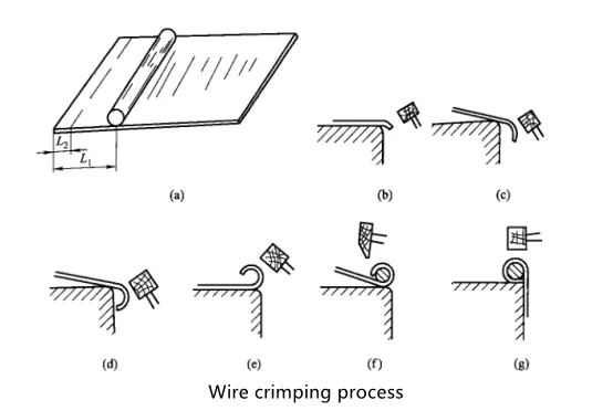
●Put the iron wire into the curling edge, start from one end when putting it, to prevent the iron wire from popping out, first buckle one end, then put a section to buckle a section, after all, buckles, tap lightly so that the curling edge is close to the iron wire, as shown in the figure Shown.
●Turn over the blank, make the interface lean against the edge of the platform, tap gently to make the interface bite, as shown in the figure.
The operation process of manual hollow crimping is the same as that of wire clamping, that is, the iron wire is pulled out at the end. When pulling, just clamp one end of the iron wire, turn the part while pulling it out. The pulling out can be done directly by hand or by the rotation of electric tools such as a hand drill.
⒉Example of crimping: In the actual crimping operation process, it is often necessary to complete other processing procedures and with the help of some crimping molds.

●Draw the start and end lines according to the size, and trim the edge burrs with a fine file.
●Pull the edge on the arc top iron by pressing the starting line to make the bend be 85°~90°, as shown in the figure; then raise the pot body until the final line is flush with the top iron and curl the edge.
●Insert the curled end of the pot body into the round rod-shaped top iron, and tap the curled part with a hammer lightly and evenly to buckle inward to form an arc.
●Place the curled part on the edge of the platform, and use a hammer to tap and level the upper part.
●Shaping on the groove top iron with the outer diameter of the dry crimping edge, such as a concave arc.