Crank Press Overview: Structure and Working Principles

The crank press is a type of mechanical press and can also be called a crank press. Its working principle is a crank-slider mechanism.
1. Working Principle and Structure
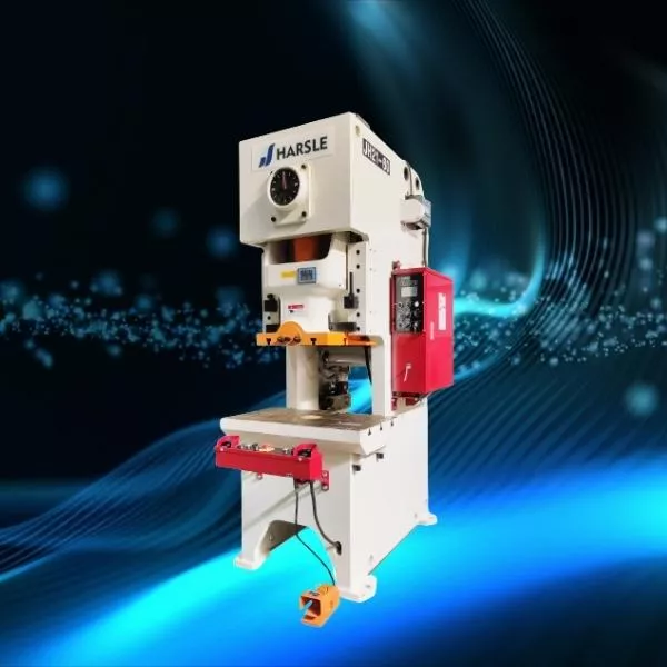
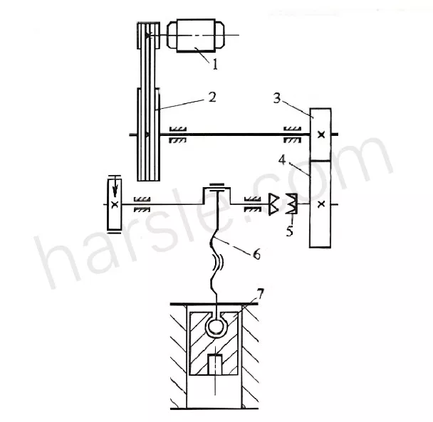
Figure 1 is an outline drawing, Figure 2 is a motion diagram.
Its working principle is as follows: motor
⑴ Pass the movement to the large pulley through the V-belt
⑵ After the pinion
⑶ Big gear
⑷ Pass to the clutch
⑸ Clutch 5 transmits the motion to the crankshaft
⑹ The upper end of the connecting rod is mounted on the crankshaft, and the lower end is connected to the slider.
⑺ The rotary motion of the crankshaft is changed to a linear reciprocating motion of the slider. The upper mold of the mold is mounted on the slider, and the lower mold is mounted on the table. Therefore, when the material is placed between the upper and lower molds, punching and other stamping processes can be performed. Due to the needs of the production process, the slider sometimes moves and sometimes stops.
Therefore, in addition to the clutch, a brake is also installed at the end of the crankshaft, and the crank press operates for a short period of time during the entire working cycle, that is, the load is working. The time is short and most of the time is no load dead time. In order to make the load of the motor uniform and use energy efficiently, a flywheel is installed. The large pulley 2 acts as a flywheel.
As can be seen from the above working principle, the crank press consists of the following parts:
(1) Working mechanism: crank slider mechanism consisting of the crankshaft, connecting rod, slider, and other parts.
(2) Transmission system: including gear transmission, belt transmission, and other mechanisms.
(3) Operating system: such as clutches and brakes.
(4)Energy system: such as electric motor, flywheel.
(5) Support parts: such as the fuselage.
2. The common structure on the crank slider
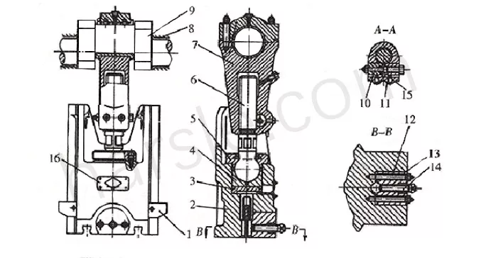
⑴Modulus height adjustment device
In order to accommodate mold installations with different closing heights, there is a device for adjusting the height of the press in the crankshaft slider of the press. As shown in the figure, the brake crank slider mechanism diagram. In the adjustment, first, loosen the top wire 15, then loosen the locking screw 10, and then rotate the adjusting rod 6, so that the length of the connecting screw is long or shortened, so that the height of the mold is reduced or increased.
After the mold is installed and debugged, the screw 10 and the top wire 15 should be locked one after another to prevent the connecting rod from returning. For large and medium-sized presses, the adjustment screw is rotated by a separate motor through a gear or turbine mechanism.
⑵Top piece device
The press is generally provided with a top piece device on the slider member for the top die of the upper die. The top piece device is rigid and pneumatic, and only the rigid top piece device is described below.
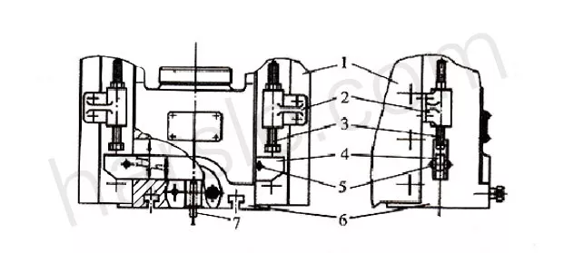
As shown, the top piece assembly consists of a hitter rail 4 that passes through the slider and a stop screw 3 that is attached to the fuselage. When the slider is pressed down, due to the action of the workpiece, the ejector rod 7 of the upper die is raised in the slider by using the traverse bar. When the slider returns to the top dead center, the two ends of the hitting bar are blocked by the head screw of the fuselage, the slider continues to rise, and the hitting bar moves downward relative to the slider, pushing the top in the upper die. The rod workpiece is ejected.
The maximum working stroke of the hitting crossbar is H-h. If the head screw is touched too early, equipment failure will occur. Therefore, when the head screw is used, the slider should be at the top dead center.
The rigid top piece device has a simple structure, reliable operation, and wide application. However, the top material force and the top material position cannot be adjusted arbitrarily.


