


The Working Principle of Gear Pump
In my exploration of hydraulic systems, I have come to appreciate the working principle of gear pumps. These pumps are essential for transferring fluids in various applications due to their reliability and efficiency. Understanding how gear pumps operate allows me to troubleshoot issues effectively and optimize system performance. In this article, I will delve into the fundamental mechanics behind gear pumps, explaining their design, operation, and advantages. My goal is to provide valuable insights that can help others in the field enhance their understanding and application of this vital technology.
●The basic concept of gear pump
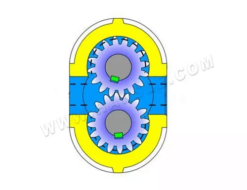
The concept of a gear pump is very simple. Its most basic form is that two gears of the same size mesh and rotate with each other in a close-fitting shell. The inside of the shell is similar to the “8” shape, and two gears are installed inside. The outer diameter and both sides of the gear are closely matched with the housing. The material from the extruder enters the middle of the two gears at the suction port, and fills the space, moves along the housing with the rotation of the teeth, and is finally discharged when the two teeth mesh.
In terms of terminology, a gear pump is also called a positive displacement device, which is like a piston in a cylinder. When one tooth enters the fluid space of another tooth, because the liquid is incompressible, the liquid and the tooth cannot be in the same Time occupies the same space, so that the liquid is mechanically squeezed out.
Due to the continuous meshing of the teeth, this phenomenon occurs continuously, so a continuous discharge amount is provided at the outlet of the pump, and the discharge amount is the same for every revolution of the pump. With the uninterrupted rotation of the drive shaft, the pump continuously discharges fluid. The flow of the pump is directly related to the speed of the pump.
In fact, there is a small amount of fluid loss in the pump, because these fluids are used to lubricate the bearings and both sides of the gears, and the pump body can never fit without clearance, so the fluid cannot be discharged from the outlet 100%, so A small amount of fluid loss is inevitable, which prevents the pump’s operating efficiency from reaching 100%. However, the pump can still run well, and for most extruded materials, it can still reach an efficiency of 93% to 98%.
For fluids whose viscosity or density changes during the process, this pump will not be affected too much. If there is a damper, such as a strainer or a restrictor on the side of the discharge port, the pump will push the fluid through them. If this damper changes during operation, that is, if the filter screen becomes dirty, clogged, or the back pressure of the limiter increases, the pump will maintain a constant flow rate until the mechanical limit of the weakest component in the device is reached .
There is a limit to the speed of a pump, which mainly depends on the process fluid. If the oil is conveyed, the pump can rotate at a high speed, but when the fluid is a high-viscosity polymer melt This restriction will be greatly increased during physical activity.
It is very important to push the high-viscosity fluid into the two-tooth space on the side of the suction port. If this space is not filled, the pump will not be able to discharge the accurate flow rate, so the PV value is also another limiting factor and a process variable. Due to these limitations, gear pump manufacturers will provide a series of products, namely different specifications, and displacement. These pumps will be matched with the specific application process to optimize the system capacity and price.
The gear and shaft of the PEP-II pump are integrated, and the whole body hardening process is adopted to obtain a longer working life. The “D” type bearing incorporates a forced lubrication mechanism, allowing the polymer to pass through the bearing surface and return to the inlet side of the pump to ensure effective lubrication of the rotating shaft. This feature reduces the possibility of polymer retention and degradation. The precision-machined pump body can accurately match the “D” type bearing with the gear shaft to ensure that the gear shaft is not eccentric to prevent gear wear. Parkwood seal structure and PTFE lip seal together constitute a water-cooled seal.
This kind of seal does not actually touch the surface of the shaft. Its sealing principle is to cool the polymer to a semi-molten state to form a self-sealing. Rheoseal seal can also be used, which has reverse spiral grooves on the inner surface of the shaft seal, so that the polymer can be back pressured back to the inlet. In order to facilitate installation, the manufacturer has designed a ring bolt mounting surface to match the flange mounting of other equipment, which makes the manufacture of cylindrical flanges easier.
The PEP-II gear pump has heating elements that match the specifications of the pump, which can be selected by users, which can ensure rapid heating and heat control. Different from the heating method in the pump body, the damage of these components is limited to one board and has nothing to do with the entire pump.
●Drive device
The gear pump is driven by an independent motor, which can effectively block upstream pressure pulsation and flow fluctuations. The pressure pulsation at the outlet of the gear pump can be controlled within 1%. Using a gear pump on the extrusion line can increase the flow rate and reduce the shear and residence time of the material in the extruder.
The external gear pump is the most widely used gear pump, and generally refers to the external gear pump. Its structure is shown in Figure 1, mainly composed of driving gear, driven gear, pump body, pump cover, and safety valve. The sealed space formed by the pump body, pump cover, and gear is the working room of the gear pump. The axles of the two gears are respectively installed in the bearing holes on the two pump covers, and the driving gear shaft extends out of the pump body and is driven to rotate by the motor. The external gear pump has a simple structure, light weight, low cost, reliable operation, and wide application range.
When the gear pump works, the driving wheel rotates with the motor and drives the driven wheel to rotate. When the meshing teeth on one side of the suction chamber are gradually separated, the volume of the suction chamber increases and the pressure decreases, and the liquid in the suction pipe is sucked into the pump; the suction liquid is pushed into the discharge chamber by the gear in the tooth groove in two ways.
After the liquid enters the discharge chamber, the gear teeth of the two gears continuously mesh, so that the liquid is squeezed from the discharge chamber into the discharge pipe. The driving gear and the driven gear rotate continuously, and the pump can continuously suck and discharge liquid.
The pump body is equipped with a safety valve. When the discharge pressure exceeds the specified pressure, the conveying liquid can automatically open the safety valve to return the high-pressure liquid to the suction pipe.
The internal gear pump is composed of a pair of internal gears meshing with each other, crescent-shaped pieces, pump casings, etc. between them. The role of the crescent-shaped piece is to separate the suction chamber from the discharge chamber. When the driving gear rotates, a partial vacuum is formed where the gear disengages and the liquid is sucked into the pump to fill the teeth of the suction chamber, and then enter the discharge chamber in two ways along the inner and outer sides of the crescent-shaped piece. Where the gear teeth enter the mesh, the liquid existing between the teeth is squeezed and sent into the discharge pipe.
In addition to the characteristics of self-priming capacity, flow and discharge pressure, the gear pump has no suction valve and discharge valve on the pump casing. It has the characteristics of simple structure, uniform flow, reliable operation, but low efficiency, high noise and vibration, and easy to wear. It is mainly used to transport various oils that are non-corrosive, non-solid particles and have lubricating ability, and the temperature generally does not exceed 70 ℃, such as lubricating oil and edible vegetable oil. The general flow range is 0.045-30ms/h, the pressure range is 0.7-20MPa, and the working speed is 1200-4000r/min.
●Structural features
⑴ Simple structure and cheap price;
⑵ Low work requirements and wide application;
⑶ The end caps and the inter-tooth grooves of the gear form many fixed sealed working chambers, which can only be used as a quantitative pump.
The gear adopts the new technology of the international advanced level in the 1990s-double arcsine curve tooth profile arc. Compared with involute gears, its most prominent advantage is that there is no relative sliding on the tooth profile surface during the gear meshing process, so the tooth surface has no wear, running balance, no liquid trapping, low noise, long life, and high efficiency. The pump gets rid of the shackles of traditional design, making the gear pump enter a new field in design, production, and use.
●Gear Pump classification
As far as the core component gears are concerned, they are mainly composed of common normal gear pumps and arc gear pumps. Common normal gear pumps are more durable than circular arc gear pumps when transporting impurity media, and circular arc gear pumps have a special structure, transport clean media, low noise, and long life. Each has its own advantages.