3 Secrets You Don’t Know About Gear Pumps

The gear pump is a rotary pump that relies on the change and movement of the working volume formed between the pump cylinder and the meshing gear to transport liquid or pressurize it. Two enclosed spaces are composed of two gears, a pump body, and front and rear covers. When the gears rotate, the volume of the space on the side of the gear disengagement increases from small to form a vacuum to suck in liquid, and the volume of the space on the gear mesh side increases from large Small, and squeeze the liquid into the pipeline. The suction cavity and the discharge cavity are separated by the meshing line of the two gears. The pressure at the outlet of the gear pump depends entirely on the resistance at the outlet of the pump.
1. Gear Pump Working Principle
Basic Concepts:
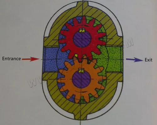
The concept of a gear pump is very simple. Its most basic form is that two gears of the same size mesh and rotate with each other in a close-fitting shell. The inside of the shell is similar to the “8” shape, and two gears are installed in it. The outer diameter and both sides of the gear are tightly matched with the housing. The material from the extruder enters the middle of the two gears at the suction port, and fills this space, moves along the housing with the rotation of the teeth, and is finally discharged when the two teeth mesh.

In terms of terminology, a gear pump is also called a positive displacement device, which is like a piston in a cylinder. When a tooth enters the fluid space of another tooth, because the liquid is incompressible, the liquid and the tooth cannot be at the same time occupies the same space, so that the liquid is mechanically squeezed out. Due to the continuous meshing of the teeth, this phenomenon occurs continuously, so a continuous discharge amount is provided at the outlet of the pump, and the discharge amount is the same for each revolution of the pump. With the uninterrupted rotation of the drive shaft, the pump continuously discharges fluid. The flow rate of the pump is directly related to the speed of the pump.
In fact, there is a small amount of fluid loss in the pump, because these fluids are used to lubricate the bearings and both sides of the gears, and the pump body can never fit without clearance, so 100% of the fluid cannot be discharged from the outlet, so A small amount of fluid loss is inevitable, which prevents the pump’s operating efficiency from reaching 100%. However, the pump can still run well, and for most extruded materials, it can still reach an efficiency of 93% to 98%.
For fluids whose viscosity or density changes during the process, this pump will not be affected too much. If there is a damper, such as a strainer or a restrictor on the side of the discharge port, the pump will push the fluid through them. If this damper changes during operation, that is, if the filter screen becomes dirty, clogged, or the backpressure of the limiter increases, the pump will maintain a constant flow rate until the mechanical limit of the weakest part of the device is reached.
There is actually a limit to the speed of a pump, which mainly depends on the process fluid. If the oil is conveyed, the pump can rotate at a very high speed, but when the fluid is a high-viscosity polymer melt In physical activity, this restriction will be greatly increased.
It is very important to push the high-viscosity fluid into the two-tooth space on the side of the suction port. If this space is not filled, the pump will not be able to discharge an accurate flow rate, so the PV value is also another limiting factor and a process variable. Due to these limitations, gear pump manufacturers will provide a series of products, namely different specifications, and displacement. These pumps will be matched with the specific application process to optimize the system capacity and price.
Drive Device:
The gear pump is driven by an independent motor, which can effectively block upstream pressure pulsation and flow fluctuations. The pressure pulsation at the outlet of the gear pump can be controlled within 1%. Using a gear pump on the extrusion production line can increase the flow output speed and reduce the shear and residence time of the material in the extruder.
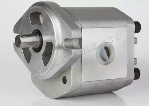
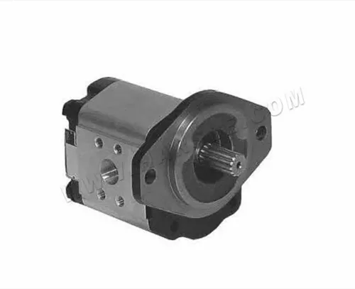
The external gear pump is the most widely used. Generally, the gear pump usually refers to the external gear pump. Its structure is shown in the figure, mainly composed of driving gear, driven gear, pump body, pump cover, and safety valve. The sealed space formed by the pump body, pump cover, and gear is the working room of the gear pump. The axles of the two gears are respectively installed in the bearing holes on the two pump covers, and the driving gear shaft extends out of the pump body and is driven by the motor to rotate. The external gear pump is simple in structure, light in weight, low in cost, reliable in work, and has a wide range of applications.
When the gear pump is working, the driving wheel rotates with the motor and drives the driven wheel to rotate. When the meshing teeth on one side of the suction chamber gradually separate, the volume of the suction chamber increases and the pressure decreases, and the liquid in the suction pipe is sucked into the pump; the suction liquid is pushed into the discharge chamber by the gear in the tooth groove in two ways. After the liquid enters the discharge chamber, the gear teeth of the two gears continuously mesh, so that the liquid is squeezed and enters the discharge pipe from the discharge chamber. The driving gear and the driven gear rotate continuously, and the pump can continuously suck and discharge liquid.
The pump body is equipped with a safety valve. When the discharge pressure exceeds the specified pressure, the conveying liquid can automatically open the safety valve to return the high-pressure liquid to the suction pipe.
The internal gear pump is composed of a pair of internal gears meshing with each other, crescent-shaped pieces, pump casings, etc. between them. The role of the crescent-shaped piece is to separate the suction chamber from the discharge chamber. When the driving gear rotates, a partial vacuum is formed where the gears are disengaged, and the liquid is sucked into the pump to fill the teeth of the suction chamber, and then enters the discharge chamber in two ways along the inner and outer sides of the crescent-shaped piece. Where the gear teeth enter the mesh, the liquid existing between the teeth is squeezed and sent into the discharge pipe.
In addition to the characteristics of self-priming capacity, flow, and discharge pressure, the gear pump has no suction valve and discharge valve on the pump casing. It has the characteristics of simple structure, uniform flow, and reliable operation, but it has low efficiency, high noise, and vibration, and is easy to wear. , It is mainly used to transport various oils that are non-corrosive, non-solid particles, and have the lubricating ability, and the temperature generally does not exceed 70 ℃, such as lubricating oil, edible vegetable oil, etc. The general flow range is 0.045-30ms/h, the pressure range is 0.7-20MPa, and the working speed is 1200-4000r/min.
Structural Features:
● Simple structure and low price;
● Low work requirements and wide application;
● The end caps and the inter-tooth grooves of the gears form many fixed sealed working chambers, which can only be used as quantitative pumps.

The gear adopts the new technology of the international advanced level in the 1990s-double arcsine curve tooth profile arc. Compared with involute gears, its most prominent advantage is that there is no relative sliding on the tooth profile surface during gear meshing, so the tooth surface has no wear, running balance, no liquid trapping, low noise, long life, and high efficiency. The pump gets rid of the shackles of traditional design, making the gear pump enter a new field in design, production, and use.
The pump is equipped with a differential pressure safety valve as overload protection, and the total return pressure of the safety valve is 1.5 times the rated discharge pressure of the pump. It can also be adjusted according to actual needs within the allowable discharge pressure range. However, this safety valve cannot be used as a pressure-reducing valve for a long time, and the pressure-reducing valve can be installed separately when needed.
The pump shaft end seal is designed in two forms, one is a mechanical seal, and the other is a packing seal, which can be determined according to specific use conditions and user requirements.
2. Work Characteristics
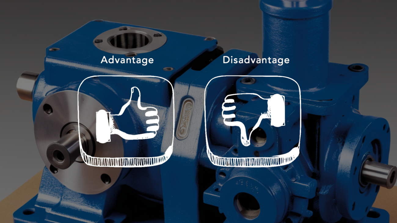
Advantages: Simple and compact structure, small size, light weight, good manufacturability, low price, strong self-suction, insensitive to oil pollution, large speed range, resistance to shock loads, easy maintenance, and reliable work.
Disadvantages: Unbalanced radial force, large flow arteries, high noise, low efficiency, poor interchangeability of parts, difficult to repair after wear, and cannot be used as a variable pump.
Oil Trapping:
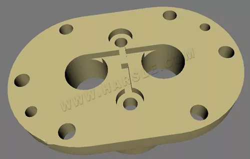
Reason: During the operation of the involute gear pump, because the enclosed volume at the intersection of the gears changes with time, a part of the hydraulic oil is often sealed between the teeth. As shown in Figure, it is called the phenomenon of oil trapping. The incompressible hydraulic oil will cause great vibration and noise to the external gear, which will affect the normal operation of the system.
Measures: Open unloading grooves on the front and rear cover plates or floating sleeves, and the principle of opening the unloading grooves: the distance between the two grooves is the minimum closed volume, and the closed volume is changed from large to small to communicate with the pressure oil chamber, and the closed volume It communicates with the oil suction cavity when it changes from small to large.

Leakage:
The leakage of the gear pump is relatively large. The leakage path of the external meshing gear is as follows: one is the gear head clearance, the second is the clearance test, and the third is the meshing clearance.
Among them, the end face backlash leakage is relatively large, accounting for 80%-85% of the total leakage. When the pressure increases, the former will not change, but the latter will greatly increase the deflection. This is the main reason for the leakage of external gear pumps, volumetric efficiency it is low, so it is not suitable for high-pressure pumps.
Efficiency:
Gear pumps are efficient in handling viscous fluids and provide a consistent flow rate.They are generally less efficient with thin or low-viscosity fluids due to increased internal leakage.
Solution: The end face gap compensation adopts static pressure balance measures, and a compensation part is added between the gear and the cover, such as a floating bushing and a floating side plate.
Unbalanced force:
The right side is the oil pressure chamber, and the left side is the oil suction chamber. The pressures of the two chambers are unbalanced; in addition, the pressure of the oil pressure chamber decreases gradually due to tooth top leakage. The two unbalanced pressures act on the radial unbalanced pressure of the gear and the shaft scale. The higher the oil pressure, the greater the force will accelerate bearing wear, reduce bearing life, bend the shaft, and increase the wear of tooth tops and shaft holes.
Preventive measures: Use pressure balance grooves or reduce pressure oil chambers.
3. Common Faults
Can’t Discharge
Trouble phenomenon: Pump can not discharge.
The cause of the failure: The direction of rotation is opposite; the suction or discharge valve is closed; the inlet has no material or the pressure is too low; the viscosity is too high, and the pump cannot bite the material.
Countermeasures: Confirm the direction of rotation; confirm whether the valve is closed; check the valve and pressure gauge; check the viscosity of the liquid, whether the flow rate proportional to the speed appears when running at low speed if there is flow, the inflow is insufficient.
Insufficient flow:
Trouble phenomenon: Insufficient pump flow.
The cause of the failure: The suction or discharge valve is closed; the inlet pressure is low; the outlet pipeline is blocked; the stuffing box is leaking; the speed is too low.
Countermeasures: Confirm whether the valve is closed; check whether the valve is open; confirm whether the discharge volume is normal; tighten; when a large amount of leakage affects the production, the operation should be stopped and disassembled for inspection; check the actual speed of the pump shaft.
Abnormal sound:
Trouble phenomenon: Abnormal sound.
Reasons for failure: Large coupling eccentricity or poor lubrication; motor failure; abnormal reducer; poor installation of shaft seal; shaft deformation or wear.
Countermeasures: Align or fill with grease; check the motor; check the bearings and gears; check the shaft seal; check the disassembly of the vehicle.
Overcurrent:
Trouble phenomenon: Excessive current.
The cause of the failure: The outlet pressure is too high; the melt viscosity is too high; the shaft package is poorly matched; the shaft or bearing is worn; the motor is faulty.
Countermeasures: Check the downstream equipment and pipelines; check the viscosity; check the shaft seal and adjust appropriately; check after stopping, whether the hand crank is too heavy; check the motor.