Comprehensive Guide To The Shearing Process

Introduction
The shearing process is a fundamental operation in the realm of metalworking and manufacturing, crucial for the precise cutting of various materials, especially sheet metals. It involves the removal of material along a designated line by subjecting it to shear forces, resulting in a clean and accurate cut.
At its core, shearing relies on the application of force to cause plastic deformation in the material, effectively separating it along a predetermined path. This process is commonly executed using specialized machines called shears, which feature sharp blades arranged in a manner to facilitate efficient cutting.
Key components of the shearing process include the workpiece, which is the material being cut, and the shear blades, which execute the cutting action. The material is positioned between the blades, and as force is applied, the blades exert sufficient pressure to induce deformation and separation along the cutting line.
Various factors influence the effectiveness of the shearing process, including the material properties such as thickness, hardness, and ductility, as well as the blade sharpness, clearance, and alignment. Proper control of these parameters is essential to achieving precise cuts with minimal distortion or defects.
The use of shears in sheet metal production has diminished through the use of cut-off tooling in CNC punching and the use of shake-out technology to separate parts from the sheet skeleton. Shears are mainly used for shearing rectangles or strips for stamping and CNC press dies.
In those cases where shearing process is used to achieve final dimensions, the thickness of the material and the X-Y dimension of the part dic- tate the degree of precision which is feasible eco- nomically. Thicker material and greater X-Y dimensions require more generous tolerances.
In the broad range of sheet metal produc- tion, material thicknesses vary from 0.005 in. (0.13 mm) to 0.25 in. (6.35 mm) in ferrous and non ferrous materials. Shearing equipment varies, accordingly, from 1⁄4 in. (6.0 mm) capacity x 12 ft. (3.5 m) bed length to tiny hand operated shears with a 0.030 in. (0.8 mm) capacity and a 12 in. (300 mm) blade length.
In the X-Y dimension a tolerance of ±0.060 in. (1.52 mm) is used for thicker material and ±0.010 in. (0.26 mm) for thinner material. It is advisable to consult your metalforming supplier for the capabilities of available equipment.
Nature of Cut Edges
Whenever sheet metal is cut, whether by punches and dies, shear or slitters, the charac- teristics of the cut edges are similar (Figure 1).
Cutting action takes place in three stages as the cutting edge moves through the material: initial plastic deformation, penetration, and fracture. During initial plastic deformation, the “edge radius” or “roll over” is formed. During penetration, the “cut band” or “burnish” is cre- ated. And during fracture, the “break” or “break-off” and the burr are developed.

Shears and other metal cutting devices are normally maintained and adjusted to provide acceptable cut quality with nominal burrs and to limit wear on tooling and equipment. This produces a cut in which penetration occurs to a depth of approximately 1⁄3 of the material thick- ness and fracture occurs through the remaining material. Proper adjustment generates a burr which seldom exceeds 10% of the material thickness.
Equipment Characteristics
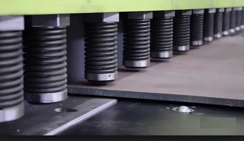
A wide variety of power shearing equipment is in use. Major machine elements common to most shears include the frame assembly, bed, table, ram, hold-down devices, gauges, the acti- vating mechanism and the blades (Figure 2). Hold-down devices, arranged along the bed near the blade, engage the stock and clamp it firmly in position for shearing.

Back gauges serve to position the stock under the moving blade at a predetermined dimension. They may range from simple, posi- tive, mechanical stops to a series of probes (proximity switches) which sense the stock and activate the machine when more than one are contacted simultaneously. Depending on type and sophistication, back gauges may be set manually or programmed.
Front gauges are often used to position the stock, especially when large workpieces are involved. They may be either mechanical or programmable.
Side gauges, also known as “squaring arms,” are mounted perpendicular to the blade on either the left or right side of the bed, and assist in guiding and squaring the stock to the blade.
Operation
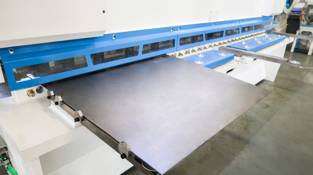
Regardless of construction, size or speed, all power shears operate similarly. A sheet of stock is advanced on the table until the back gauges are contacted and the line of cut is beneath the blade (Figure 3). When the machine is activat- ed, the hold-down devices clamp the stock and the angled moving blade cuts progressively across the sheet in a guillotine-like action.

Depending on the application, power shears may be fed from the front or the back. Back feeding can reduce handling of the stock for subsequent cuts, but requires an additional operator.
Maintaining Quality
Important quality checks are performed dur- ing the shearing operation. Factors of quality control include the initial flatness of the stock, general surface and edge condition. Surface flaws and skid marks are common on coil and sheet products and are generally acceptable to the manufacturer unless such marks would cause cosmetic rejection of the finished prod- uct. Delamination, surface inclusions and other severe defects in the material may also be iden- tified and are cause for rejection.
Design Considerations
For economical production the knowledge- able designer recognizes several aspects affect- ing costs and quality during shearing and in subsequent operations. Following are several such product design considerations.
●Material Utilization:Material suppliers generally make sheet stock available in stan- dard sizes—widths of 30, 36, 48 and 60 inches. Significant savings can result from the effective use of these standard sizes by avoiding charges for extra slitting or mill preparation.Early consultation with the metalformer may permit modifying the dimensions of unseen flanges on the product to achieve an overall part layout somewhat smaller than the standard sheet size. This can avoid extra costs and reduce waste.
●Grain Direction:Grain direction in flat rolled stock (lengthwise in the coil) is not always a significant consideration. However, in some operations such as forming and bending, grain orientation can be important.On very large parts which have formed flanges or features, the designer should consult a qualified supplier prior to specifying the grain orientation and bend radius to determine if material size limitations will permit the formed features to be across the grain. This subject is explored in more detail in the chapters on Press Brake Forming and Stamping Production.

●Process Characteristics:Burrs, holddown marks and twist (Figure 4) are characteristics of the shearing process.
1. Burrs are present after shearing (as in any metal cutting operation) and are normally con- trolled within acceptable limits through proper shearing practices.
2. Hold-down marks, appearing as slight inden- tations along one side of the sheared edge of the workpiece, sometimes result from the clamping action of the hold-downs. These marks are seldom a problem. They may often be accommodated as part of an unseen flange in the final product, or may be eliminated entirely during trimming in later operations.
In critical applications, coverings on the hold-downs may be used to protect the stock. Materials with removable protective coatings are sometimes used to help reduce holddown marks and scratches that are inherent in the shearing process. These alternatives will add considerable additional cost.
3. Twist, a spiral-like curvature of the material occurs when shearing narrow strips. It is caused by the scissors action of the shear and is influ- enced by the relationship of the width sheared to the thickness and temper of the strip.
Twist is seldom an important consideration except when shearing narrow strips. When a job requires very narrow strips, roller slit coil mate- rial, (if order is of sufficient quantity) or bar stock can often be substituted.