


How Does The Press Brake Hydraulic System Work?

In my experience with press brakes, understanding how the hydraulic system works is essential for optimizing performance and ensuring precision in bending operations. The press brake hydraulic system is designed to convert hydraulic energy into mechanical force, allowing for accurate and efficient bending of metal sheets. Over the years, I’ve delved into the intricacies of this system, from the hydraulic fluid’s role to the various components that work in harmony to create the desired force. In this article, I will explain how the press brake hydraulic system works, providing insights that can help operators enhance their understanding and application of this vital technology.
Introduction
Press brake is a kind of widely used bending machine, which has already achieved hydraulic efficiency. Press brake, as an important equipment for sheet metal processing, plays an irreplaceable role, it plays a decisive role in product quality, processing efficiency and precision. Usually, the press brake is the upper piston type press machine, which is composed of the frame, sliding block, hydraulic system, front loading rack, back gauge, mold, electrical system etc, as shown in figure1.
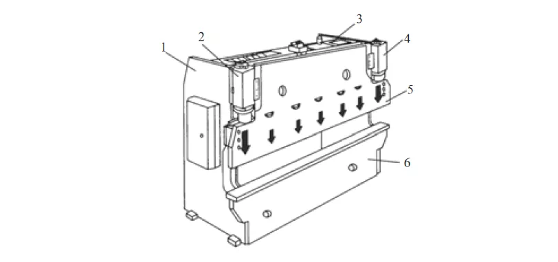
1.left upright 2.Left oil cylinder 3.Oil tank 4.Right hydraulic cylinder 5.Ram 6.Worktable
A vertical downward pressure is formed by two parallel working hydraulic cylinders to drive the die on the bending beam to complete bending process.
The hydraulic control system, as the brain of the press brake, mainly controls the synchronous operation of the bending process and the positioning of the hydraulic cylinder when the press brake machine is fully loaded.
In this post, we will analyze how does the press brake hydraulic system work?
Hydraulic system
For each bending motion, the typical bending process of the upper bending beam includes:
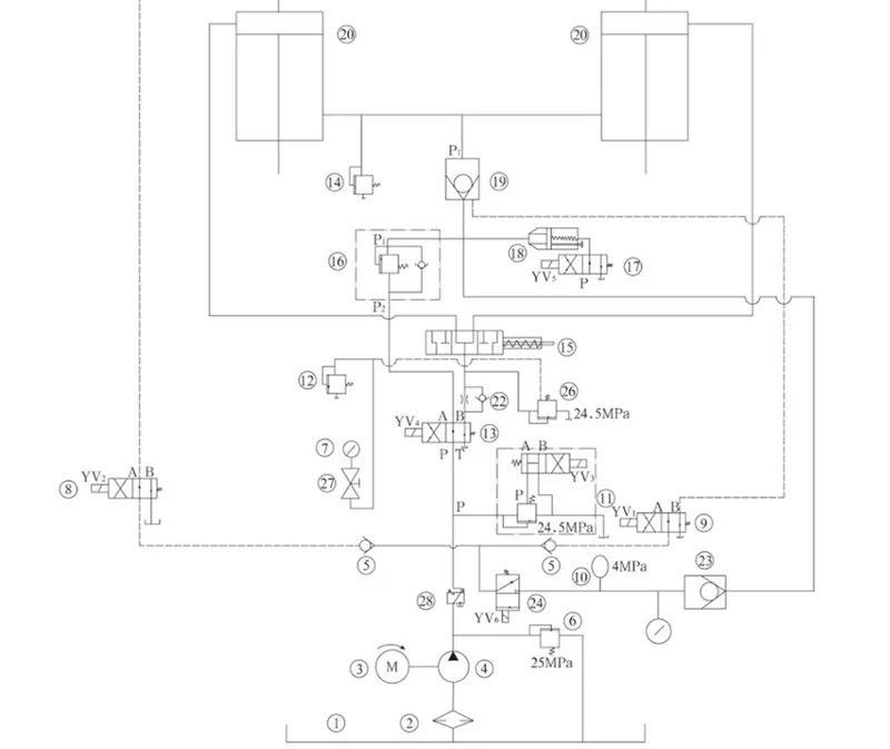
1. Oil Pump Starting
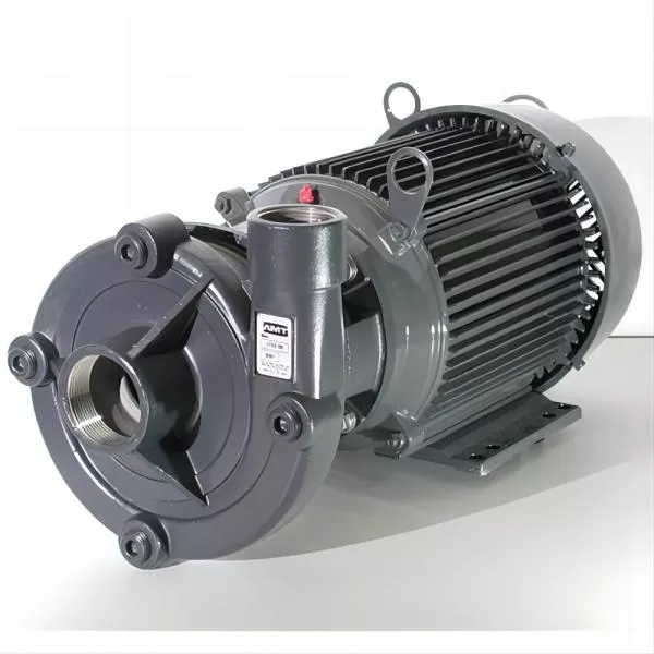
The motor will rotate in the direction indicated by the pump arrow, that is , clockwise direction, driving the axial piston pump.
The oil is discharged through the pipeline into the valve plate and the electromagnetic overflow valve to return to the tank.
When valve NO.19 is closed, the oil in the lower cavity of NO. 20 cylinder is kept in a fixed position.
2. Downward Movement
The fast descending motion of the press brake is produced by the bending beam and the self-weight of the accessories and the pressure of the oil.
In the process, the hydraulic cylinder has no rod cavity through the filling valve, and the rod cavity will produce back pressure and the oil liquid will return quickly.
The fast forward movement starts from the top dead center.
After a brief period of deceleration, the slider slows down at a certain distance from the bending plate.
When the No.YV1, No.24YV6, No. 13YV4, No.17 YV5 electromagnet are working, the sliding block drops rapidly, the descending speed is adjusted by valve No.18.
The oil in the lower chamber of the No.20 cylinder enters the tank through the 19th,18th and 17th.
The upper chamber oil of oil cylinder No.20 is injected through valve 21.
When the slider falls to the limit switch No.9 YV1,No.8 YV2, No.11YV3, No.13YV4, and No.24YV6 electromagnet work, and the ram turn into working speed.
When the slider is out of sync, the valve No.15 IS AUTOMATICALLY CORRECTED.
Sliding block drop position is restricted by mechanical block in the cylinder.
3. Bending
The bending phase begins with the pressure buildup of the non-bar cavity.
The bending speed is limited by the quantity of oil supplied by the oil pump, On the other hand, it can be adjusted by direction valve of the proportional valve.
At the same time, the direction valve also controls the synchronous operation of the bending beam and the positioning of the lower dead center.
The bending force is limited by the proportional relief valve to limit the pressure of the pump.
The corresponding values of speed, synchronization,positioning and pressure are all from the CNC.
The pedal switch or button control the electromagnet working time, which includes No.9 YV1,No.8 YV2, No.11YV3, No.13YV4, and No.24YV6 ,which realize the joggle distance when the sliding block drop.
The speed of slide drop is adjusted by valve 16
The slider is controlled up by No.11YV3 and No.24YV6.
The length of working time of the same electromagnet can realize the moving distance of the slider.
4. Pressure Relief
The stress relief of the no-bar cavity begins when it reaches the bottom of the dead center,or after a short period of holding time, in this way, the material has sufficient time to form and further improve the dimension precision of the parts.
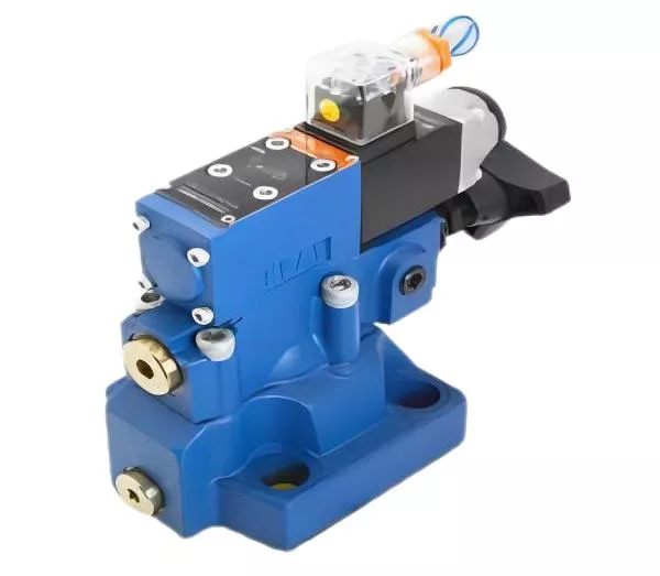
The pressure holding and pressure relief are performed by the proportional directional valve according to the numerical control device.
In order to improve the processing efficiency,the reduction time should be as short as possible.
However, in order to avoid the unloading impact in the whole system, it is required to extend the discharge time as far as possible.
In short, the pressure relief curve should be as smooth as possible , not too steep.
The optimization of the whole process is realized by the proportional directional valve.
5. Master Cylinder Return
The pump flow and the hydraulic cylinder have the pressure area of the bar cavity, which determines the maximum return speed, in most cased, close to the fastest speed.
The return also requires the synchronous operation, starting with the pressure reduction of the bar cavity to the end of the upper dead center.
At the instant of the return, it is required to reset the pressure of the No.8VY2 electromagnet for 2 seconds.
Then No.11YV3,No.24YV6 electromagnet start work,slide block return and return speed remains constant.
6. Pressure Adjustment of Press Brake
No.6 high-pressure overflow valve and No.11 electromagnetic overflow valve are mainly for maintaining the rated power of the press brake.
No.14 overflow valve regulates the return force of the machine so as not to damage the machine due to overload.
The work pressure in the hydraulic system can be read from the pressure gauge No.7.
The nitrogen pressure of the No.10 accumulator mainly controls the pressure required to operate the valve No.19/21.
America-Miami-Customer-Feeback-1.jpg)
Uzbekistan-Customer-Feedback1.png)
Kosovo-Customer-Feedback11.png)
Russia-Customer-Feedback.jpg)
Russia-Customer-Feedback-3.jpg)


