


Ao lidar com operações avançadas de prensa dobradeira, entender as opções de configuração no Modo Máquina do DELEM DA-66S é crucial. Se você está procurando especificamente o que pode configurar no Modo Máquina do DELEM DA-66S, você está no lugar certo.
Vou guiá-lo pelos aspectos vitais da configuração deste poderoso sistema de controle, garantindo que você aproveite ao máximo seus recursos para otimizar seus projetos de usinagem. Seja você um operador experiente ou iniciante nesta tecnologia, este guia fornecerá os insights abrangentes de que você precisa.
Introdução
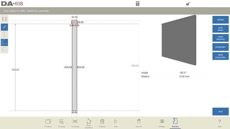
A interface do Modo Máquina DELEM DA-66S foi projetada para uma navegação amigável, crucial para uma configuração eficaz da máquina.
Com uma interface touchscreen, você pode selecionar e modificar facilmente parâmetros para se adequar a tarefas específicas. Seu design intuitivo minimiza o tempo de configuração e maximiza a produtividade. Ao tocar no botão de navegação "Máquina", o controle é alternado para o modo Máquina.
O modo Máquina do controle, que pode ser encontrado no painel de navegação, dá acesso aos itens de configuração da máquina e às características específicas da máquina que influenciam os cálculos genéricos e o comportamento da máquina.
As configurações são divididas em várias abas, localizadas na lateral da tela, organizando logicamente os diferentes assuntos. Nas seções a seguir, as abas disponíveis e os detalhes das configurações são discutidos.

A navegação pelas abas pode ser feita simplesmente tocando nelas e selecionando o item desejado para ajuste. Como pode haver mais abas do que a tela pode exibir em uma única visualização, arrastá-las na direção vertical permite visualizar e selecionar todas as abas disponíveis.
Vamos nos aprofundar para descobrir tudo o que você precisa saber sobre esse poderoso sistema de controle.
Programação de Socos
Nesta aba, os punções utilizados na máquina podem ser programados. Novos punções podem ser adicionados; os existentes podem ser editados, copiados, renomeados e excluídos.
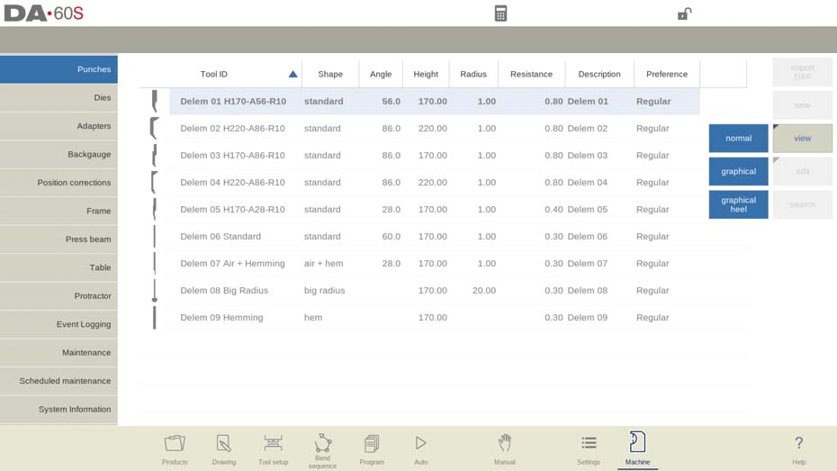
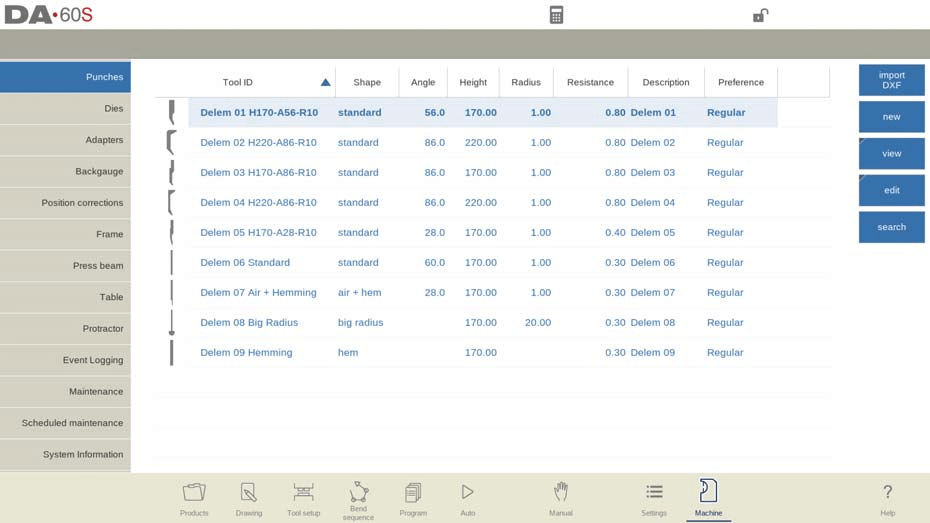
Visualizar
Na página principal, é exibida uma lista de punções disponíveis. Usando a função Exibir, semelhante ao modo Produtos, diferentes visualizações podem ser selecionadas. Além da visualização padrão Normal, também estão disponíveis as visualizações Gráfica e Calcanhar Gráfico.
Diretório gráfico
Em Gráfico a geometria das ferramentas é mostrada, bem como as principais propriedades.
Diretório gráfico perfura com saltos

No calcanhar gráfico, a geometria das ferramentas é mostrada, bem como as propriedades do calcanhar.
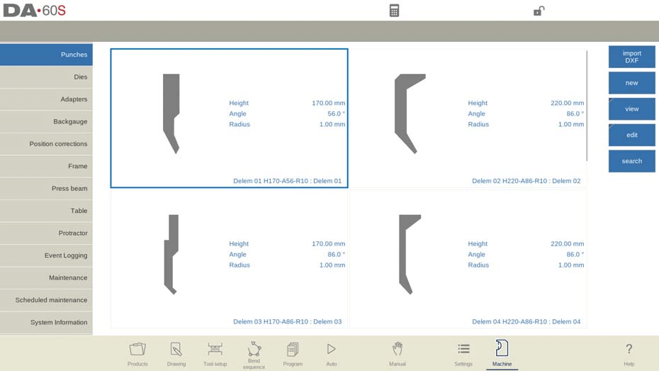
Crie um novo soco
Para começar a configurar um novo punção no Modo Máquina DELEM DA-66S, toque em "Novo" na biblioteca. Isso iniciará o processo, no qual você poderá utilizar as ferramentas de programação e desenho disponíveis no sistema de controle. Comece programando o formato do punção e atribuindo a ele um ID exclusivo.
Seleção de Formas
Escolher o formato correto do punção é fundamental para atingir a ação de dobra desejada. As opções incluem:
- Soco padrão: Ideal para dobra de ar e tarefas básicas de assentamento.
- Soco para dobrar bainha: Projetado com fundo plano para bainhas com curvas específicas.
- Soco de dobra de ar + bainha: Adequado para dobras de ar e funções de bainha.
- Punção de grande raio: Perfeito para criar curvas de raio grande.
Cada formato tem funções específicas no Modo Máquina DELEM DA-66S, então selecione com base em suas necessidades operacionais.
Atribuindo um ID
Cada punção deve ter um identificador único, de até 25 caracteres. Este pode ser uma combinação de números e letras, garantindo fácil reconhecimento e gerenciamento dentro da biblioteca de ferramentas.
Após programar a forma e o ID, selecione "Aceitar" para prosseguir com os parâmetros de dados da ferramenta. O sistema solicitará as propriedades da ferramenta, com foco inicial nas dimensões da ferramenta.
Utilizando importação DXF
Para formas mais complexas, a função opcional de importação de DXF pode ser uma ferramenta poderosa. Se você instalou esta opção, pode importar formas de punção diretamente de arquivos DXF, agilizando o processo de configuração para designs complexos.
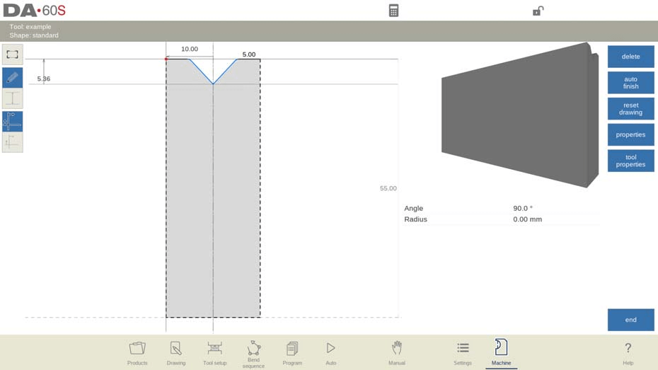
Soco padrão
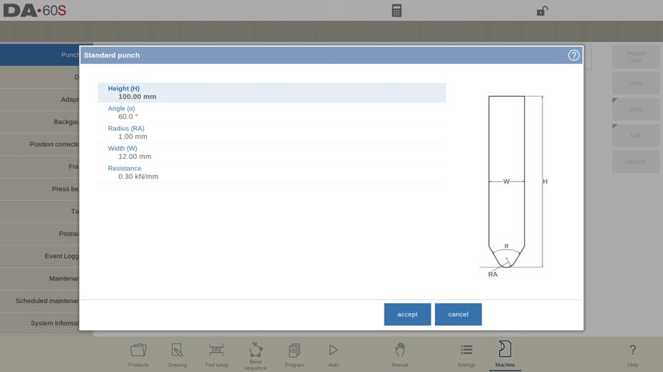
Altura
Comece definindo a altura da ferramenta. Este é um valor crucial, pois influencia diretamente o cálculo da profundidade da dobra, o que garante a precisão das suas dobras.
Ângulo
O ângulo da ponta do punção deve ser configurado precisamente para corresponder à curvatura desejada.
Raio
O raio da ponta do punção. Este valor será usado como raio interno da dobra a ser feita quando este valor for maior que o raio interno resultante do processo de dobra.
Largura
Definir corretamente a largura da ferramenta é essencial para programar dobras precisas.
Resistência
Defina a força máxima permitida na ferramenta para proteger contra esforço excessivo durante operações de dobra.
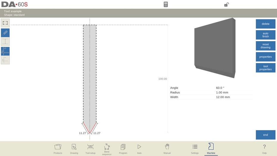
Orientação do soco na tela
Certifique-se de que o punção esteja corretamente orientado na tela. Normalmente, o lado direito da ferramenta é o lado do batente traseiro.
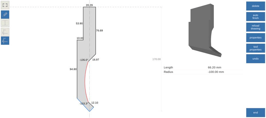
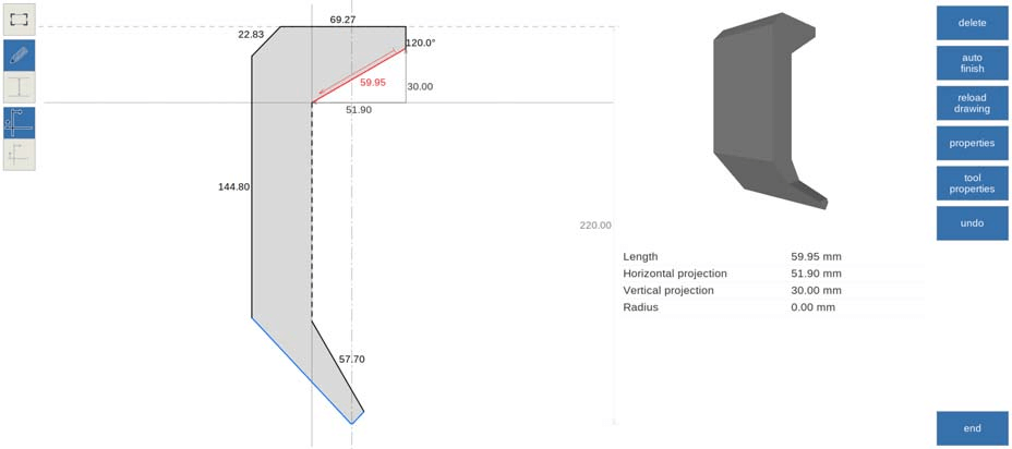
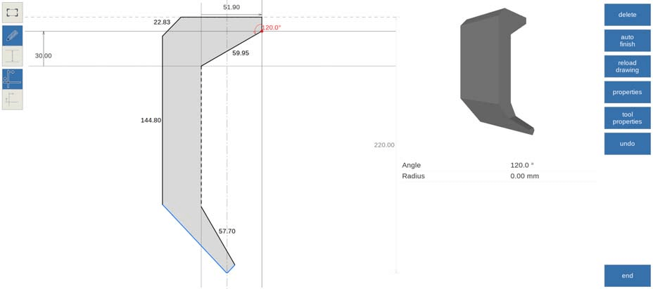
Desenho
Utilize os recursos de desenho para criar perfis de ferramentas. Insira valores de ângulo e comprimento de linha para construir o contorno da ferramenta.
Ponto de montagem (opcionalmente programável)
Defina o ponto de montagem do punção no desenho. Este ponto indica onde o punção será conectado à viga de prensagem ou ao adaptador.
Funções de desenho
As seguintes funções estão disponíveis durante o desenho. Aproveite funções como Excluir Linha, Finalização Automática, Redefinir Desenho e Recarregar Desenho para refinar ou modificar designs de ferramentas.
- Excluir linha
Para excluir um segmento de linha.
- Acabamento automático
Finalizando o contorno da ferramenta até o topo da ferramenta automaticamente.
- Redefinir desenho
Para redefinir o desenho programado da ferramenta até a forma básica inicial, ao criar um novo punção.
- Recarregar desenho
Para recarregar o desenho programado da ferramenta até a forma básica inicial, ao alterar um punção existente.
- Propriedades
Para alterar as propriedades específicas da linha ou ângulo, adicionar ou remover um raio, alterar o comprimento, etc. É possível, por exemplo, adicionar um raio no contorno da ferramenta.
A bainha pode fazer parte das propriedades das linhas. Dentro do formato de uma ferramenta, uma superfície pode ser designada como superfície de bainha. Isso habilitará a ferramenta para a operação de bainha.
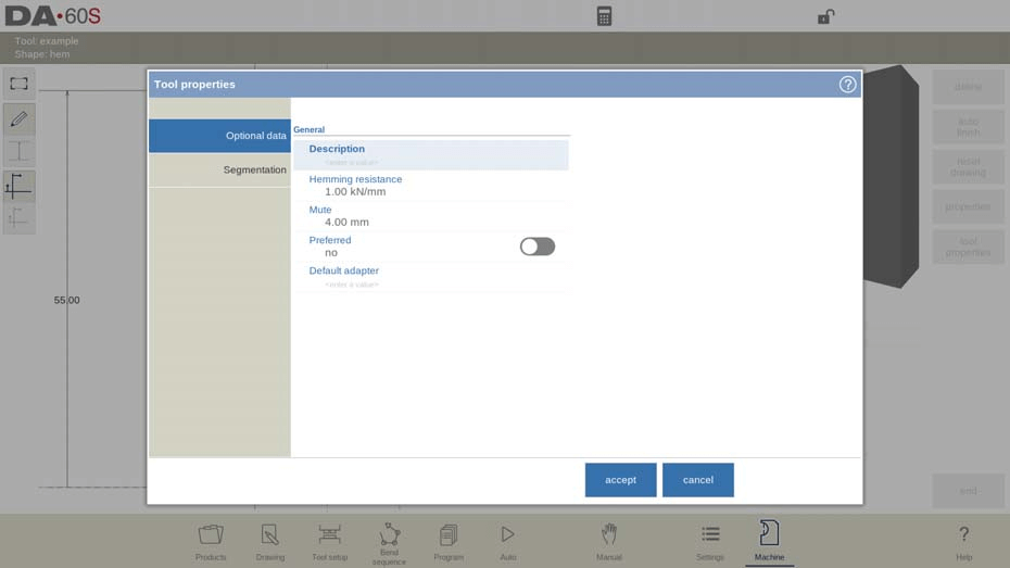
Propriedades da ferramenta
Para alterar os dados e a descrição da ferramenta genérica.
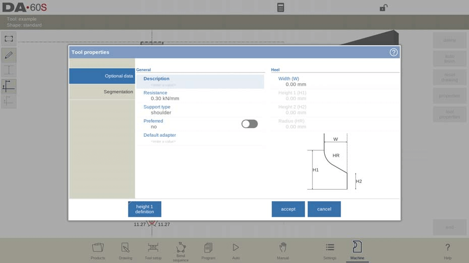
- Descrição
A descrição da ferramenta no Modo Máquina do DELEM DA-66S permite até 25 caracteres para identificar ou descrever a ferramenta. Este recurso auxilia na rápida identificação e seleção na biblioteca de ferramentas.
- Resistência
Defina a força máxima permitida na ferramenta para garantir operações seguras e eficazes. Ajustar este parâmetro corretamente no Modo Máquina DELEM DA-66S evita danos à ferramenta e melhora o desempenho.
- Tipo de suporte
Ajuste o tipo de suporte para acomodar punções montadas de forma diferente no Modo Máquina DELEM DA-66S. Isso garante precisão na altura da ferramenta e na posição do eixo Y. As opções incluem "montagem na cabeça" ou "montagem no ombro".
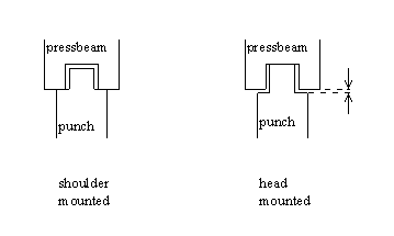
Se a opção "montagem no ombro" for escolhida, a posição do eixo Y será calculada a partir da altura padrão da ferramenta. Esta é a configuração padrão.
Se for escolhido "montado na cabeça", será feita uma correção para o cálculo do eixo Y.

- Preferido
Ao configurar o Modo Máquina DELEM DA-66S, uma etapa essencial é configurar as ferramentas preferenciais para suas tarefas de dobra.
- Adaptador padrão
Outra configuração valiosa no Modo Máquina DELEM DA-66S envolve a associação de adaptadores padrão a ferramentas usadas com frequência. Quando uma combinação específica de ferramenta e adaptador é usada regularmente, definir o adaptador como padrão simplifica seu fluxo de trabalho. Cada vez que você seleciona uma ferramenta, o adaptador padrão é carregado automaticamente, o que minimiza o tempo de configuração e reduz a probabilidade de erros.
Dimensões do salto
Largura: Largura do calcanhar.
Altura 1:Altura1 do calcanhar.
Altura 2:Altura2 do salto.
Raio: O raio no segmento do calcanhar.
As alturas 1 e 2 não influenciam a altura da ferramenta que você programou anteriormente.
Editar soco
Para editar uma ferramenta existente, toque nela na biblioteca. A ferramenta aparece na tela e pode ser editada com os recursos de desenho.
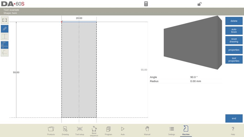
Soco para bainha
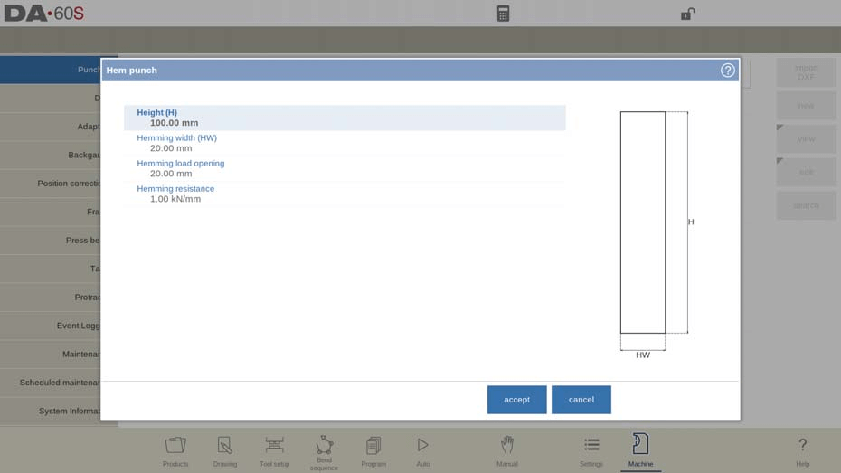
Configurar um punção para dobra de bainha no Modo Máquina DELEM DA-66S exige atenção aos detalhes e configuração precisa para garantir o desempenho ideal em suas operações com prensa dobradeira. Aqui está um guia passo a passo para ajudar você a navegar por esse processo.
Etapa 1: Defina a altura da ferramenta
Primeiro, é crucial determinar a altura total da ferramenta de punção para dobra de bainha. A altura é um parâmetro crítico, pois será usada no cálculo da profundidade da dobra no Modo Máquina DELEM DA-66S.
Etapa 2: programe a largura da bainha
O próximo passo envolve definir a largura da bainha. Esta é a largura da ferramenta que você programará no Modo Máquina do DELEM DA-66S. Definir essa largura com precisão é essencial para operações de bainha eficazes, especialmente ao trabalhar com folhas de dimensões variadas.
Etapa 3: Defina a abertura de carga da bainha
A abertura da carga de bainha é vital para acomodar o seu produto durante a dobra. Dependendo da construção da sua máquina, programe uma posição de abertura para o punção. Essa posição deve ser duas vezes maior que a espessura da chapa, garantindo que o material possa ser facilmente posicionado sem interferência, minimizando assim o tempo de preparação e os erros.
Etapa 4: Estabelecer resistência à bainha
Por fim, configure a resistência à bainha, que indica a força máxima permitida exercida sobre a ferramenta durante a bainha. Garantir que essa força esteja definida corretamente evita danos à ferramenta e mantém a qualidade da dobra.
Após inserir esses valores típicos, você pode utilizar o Modo Máquina DELEM DA-66S para criar desenhos de ferramentas precisos. Utilize os recursos de desenho inserindo valores de ângulo e comprimento de linha. As ferramentas de desenho por toque disponíveis são semelhantes às usadas em métodos de desenho de produtos, oferecendo uma transição perfeita para usuários familiarizados com essas ferramentas.
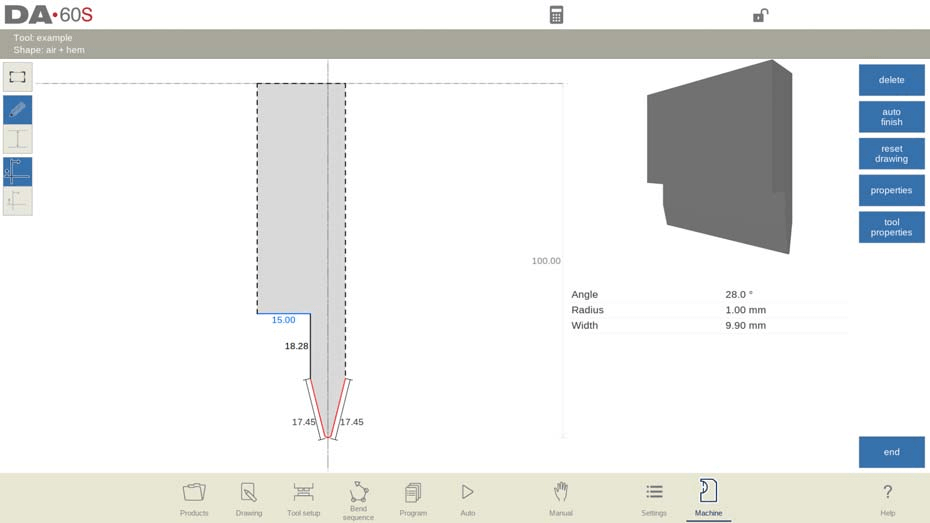
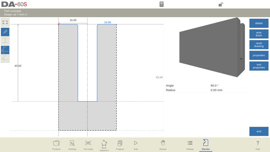
Soco de ar + dobra de bainha

Na metalurgia, a dobra e a bainha a ar são técnicas essenciais, principalmente ao utilizar sistemas de controle avançados como o Modo Máquina DELEM DA-66S. Este modo sofisticado permite configurar uma ampla gama de parâmetros para obter dobras e bainhas precisas.
Altura
Altura total da ferramenta. Importante: este valor de altura será usado no cálculo da profundidade da dobra.
Ângulo
O ângulo da ponta do punção é um fator essencial para obter a dobra desejada. O Modo Máquina DELEM DA-66S permite ajustes precisos de ângulo para atender às especificações do seu projeto.
Raio
O raio da ponta do punção serve como raio interno para a dobra. É importante observar que, se esse raio exceder o raio interno do processo, ele se torna o fator limitante. Ajustes podem ser feitos no Modo Máquina DELEM DA-66S para acomodar essas variações.
Largura
A largura da ferramenta a ser programada.
Resistência
No Modo Máquina DELEM DA-66S, você pode definir a força máxima permitida para a ferramenta.
Altura da bainha
Este parâmetro determina a altura do punção para a função de bainha.
Largura da bainha
A largura da parte do punção usada para colocar o produto na ação de bainha.
Abertura de carga de bainha
Programar a posição de abertura do punção é crucial na bainha. O Modo Máquina DELEM DA-66S considera o dobro da espessura da chapa ao definir esta abertura.

Resistência à bainha
O Modo Máquina DELEM DA-66S oferece configurações para gerenciar a força máxima permitida, protegendo ferramentas e materiais durante a bainha.
Após inserir esses valores específicos, você pode utilizar os recursos de desenho para criar o desenho da ferramenta. Isso envolve a inserção de valores de ângulo e comprimento de linha, semelhantes aos métodos de desenho de produto, e a utilização de ferramentas de desenho por toque disponíveis no Modo Máquina DELEM DA-66S.
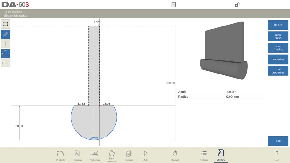
Soco de raio grande

Altura
Altura total da ferramenta. Importante: este valor de altura será usado no cálculo da profundidade da dobra.
Raio
O raio da ponta do punção.
Altura do raio
A altura da parte de raio grande da ferramenta.
Resistência
Força máxima permitida na ferramenta.
Largura superior
A largura da ferramenta na parte superior do punção.
Após inserir esses valores típicos, você pode criar o desenho da ferramenta com os recursos de desenho. O desenho de um perfil de ferramenta é feito inserindo valores de ângulo e comprimento de linha. As ferramentas de desenho por toque também estão disponíveis, assim como no método de desenho de produto.
Programação de matrizes
Nesta aba, as matrizes utilizadas na máquina podem ser programadas. Novas matrizes podem ser adicionadas; as existentes podem ser editadas, copiadas, renomeadas e excluídas.
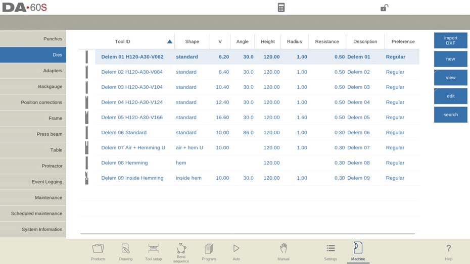
Visualizar
Na página principal, é exibida uma lista de matrizes disponíveis. Usando a função Exibir, semelhante ao modo Produtos, diferentes visualizações podem ser selecionadas. Além da visualização padrão Normal, a Visualização Gráfica também está disponível.
Diretório gráfico
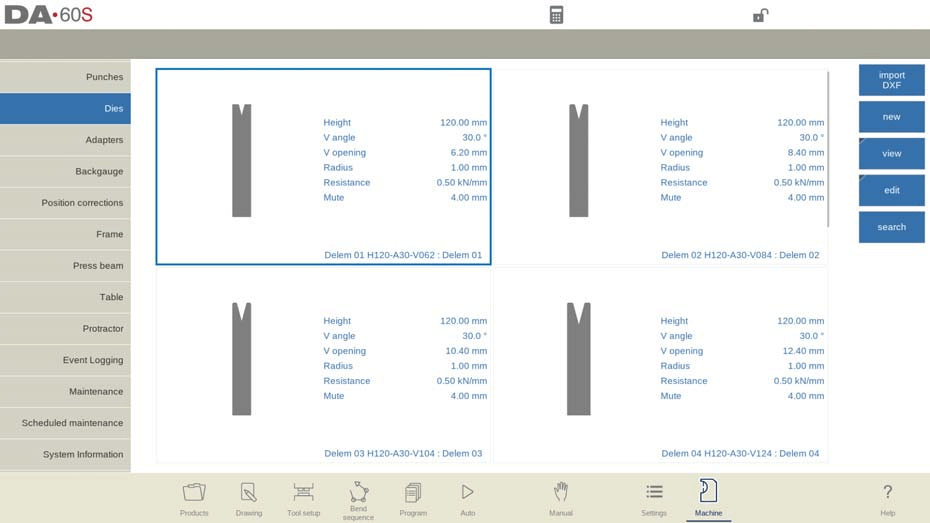
Em Gráfico a geometria das ferramentas é mostrada, bem como as principais propriedades.
Crie um novo dado
Para criar uma nova matriz, toque em "Novo" na biblioteca. O perfil da matriz pode ser criado com a ajuda dos recursos de programação e desenho do controle.
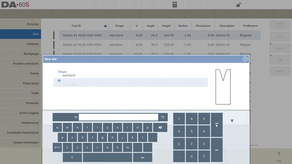
No Modo Máquina DELEM DA-66S, configurar o formato e o ID da matriz é um primeiro passo crítico para garantir a usinagem de precisão.
Forma
Selecionar o formato de matriz apropriado no Modo Máquina do DELEM DA-66S é essencial para corresponder à ação de matriz desejada. O Modo Máquina oferece várias opções, incluindo:
- Formato de matriz padrão para dobra a ar e assentamento básico.
- Matriz para dobra de bainha, projetada com uma parte superior plana para dobras de bainha específicas.
- Matriz de curvatura interna para dobras de ar acopladas à funcionalidade de bainha.
- Molde em formato de U para dobras de ar combinadas e operações de bainha específicas.
- Matriz Multi-V, atendendo a múltiplas aberturas em V e U.
- Matriz Vario-V para aberturas em V ou U ajustáveis, disponível somente com o sistema Vario-V.
- Matriz de curvatura para bainha interna Multi-V, que integra múltiplas aberturas em V ou U com um sistema de bainha.
- Matriz de dobra para bainha de porta, combinando características de matriz em V com bainha interna, ideal para produção de molduras de porta.
- Matriz Wingbend, equipada com segmentos de raio rotativo para aplicações especiais.
EU IA
Atribuir um ID exclusivo a cada ferramenta é crucial para a organização e o gerenciamento do Modo Máquina DELEM DA-66S. O ID pode ser uma combinação de até 25 caracteres alfanuméricos, facilitando a identificação e a recuperação.
Após concluir as configurações de formato e ID, você pode prosseguir com a inserção dos parâmetros de dados da ferramenta. O Modo Máquina do DELEM DA-66S o guiará na inserção das propriedades necessárias da ferramenta, começando pelas dimensões iniciais. É importante observar que os parâmetros variam dependendo do formato da matriz selecionada.
Importação DXF (disponível somente quando a opção DXF estiver instalada)
Além disso, se a opção de importação DXF estiver instalada, você pode agilizar o processo de configuração importando formas de matriz diretamente, aumentando ainda mais a flexibilidade do sistema.
Ao configurar meticulosamente essas configurações no Modo Máquina DELEM DA-66S, você garante o desempenho ideal da ferramenta e maior eficiência geral da produção.
matriz padrão
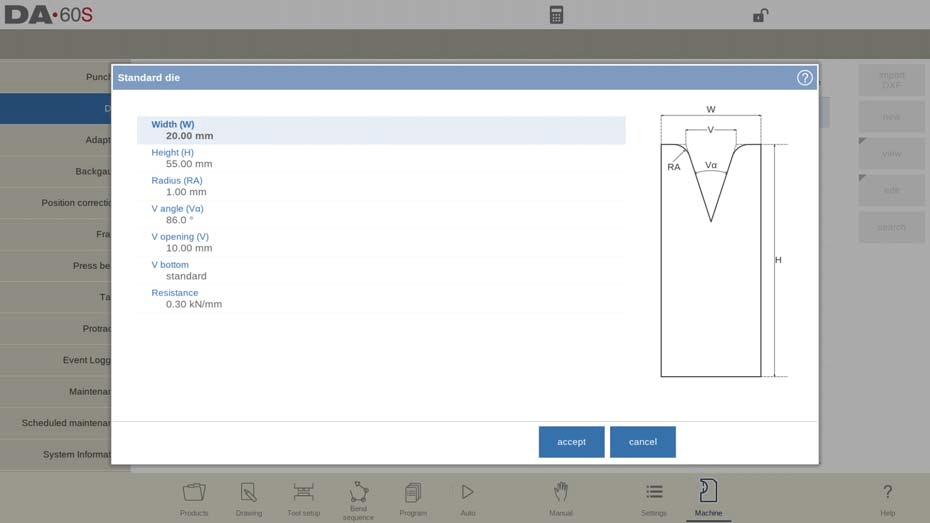
Largura
A largura da ferramenta a ser programada.
Altura
Altura total da ferramenta. Importante: este valor de altura será usado no cálculo da profundidade da dobra.
Raio
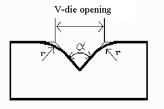
O raio das bordas da abertura em V.
ângulo V
O ângulo do dado.
Abertura em V
Abertura em V do dado. A abertura em V é a distância entre as linhas que se tocam.
Parte inferior em V
Aqui com os diferentes fundos possíveis dentro da abertura em V pode-se definir:
• O padrão é um ângulo agudo na parte inferior do dado.
• Redondo é um fundo de matriz com um raio a ser programado com o parâmetro 'Raio interno'.
• Plano é um fundo de matriz plano com uma determinada dimensão a ser definida com o parâmetro 'Largura do fundo'.
Resistência
Força máxima permitida na ferramenta.
No campo da metalurgia de precisão, o Modo Máquina DELEM DA-66S oferece uma plataforma robusta para configurar diversas ferramentas e ajustes, otimizando suas operações de prensa dobradeira.
Orientação e Desenho
O Modo Máquina DELEM DA-66S exibe com eficiência a orientação da matriz na tela. Ele posiciona o lado direito da ferramenta, alinhando a posição central da abertura em V com a linha central da prensa dobradeira.
Desenho
Utilizando os recursos de desenho do Modo Máquina DELEM DA-66S, você pode criar perfis de ferramentas detalhados inserindo valores específicos de ângulo e comprimento de linha. O modo oferece ferramentas de desenho por toque semelhantes aos métodos de desenho de produto, permitindo precisão no projeto e na configuração.
Configuração do ponto de montagem
Um recurso essencial do Modo Máquina do DELEM DA-66S é a possibilidade de programar opcionalmente o ponto de montagem da matriz. Este recurso é marcado com uma seta triangular no desenho, indicando onde a matriz se conecta e é posicionada na mesa ou em um adaptador. O sistema suporta pontos de montagem separados para posições normal e rotacionada. Além disso, se esta função não estiver habilitada, os indicadores relacionados não serão exibidos, garantindo uma interface clara.
As seguintes funções estão disponíveis durante o desenho
- Excluir linha
Para excluir um segmento de linha.
- Alterar altura
Para alterar a dimensão de altura da ferramenta.
- Acabamento automático
Finalizando o contorno da ferramenta até o topo da ferramenta automaticamente.
- Redefinir desenho
Para redefinir o desenho programado da ferramenta até a forma básica inicial, ao criar uma nova matriz.
- Recarregar desenho
Para recarregar o desenho programado da ferramenta até a forma básica inicial, ao trocar uma matriz existente.
Propriedades
Para alterar as propriedades específicas da linha ou ângulo, adicionar ou remover um raio, alterar o comprimento, etc. É possível, por exemplo, adicionar um raio no contorno da ferramenta.
A bainha pode fazer parte da propriedade das linhas. Dentro do formato de uma ferramenta, uma superfície pode ser designada como superfície de bainha. Isso permitirá que a ferramenta realize a operação de bainha.
Propriedades da ferramenta
Para alterar os dados e a descrição da ferramenta genérica.
- Descrição
Um nome ou descrição desta ferramenta. O comprimento máximo é de 25 caracteres. Esta descrição já foi inserida no início da definição da ferramenta, mas pode ser editada neste campo. A descrição está listada na visão geral da ferramenta na biblioteca.
- Resistência
Força máxima permitida na ferramenta.
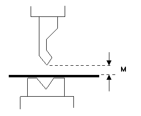
- Mudo
Distância de silenciamento. Distância acima da folha na qual ocorre a mudança de velocidade.
- Preferido
Para a seleção automática de ferramentas, com base no encaixe equivalente de uma ferramenta para uma dobra específica, este parâmetro pode indicar uma ferramenta como preferencial em relação às demais. A seleção automática de ferramentas priorizará as ferramentas indicadas como preferenciais.
- Adaptador padrão
Quando uma ferramenta é usada com um adaptador específico e essa combinação é comumente usada, o adaptador pode ser definido como padrão nas propriedades da ferramenta. Sempre que a ferramenta for selecionada, o adaptador também será carregado automaticamente na configuração da ferramenta.
Editar dado
Para editar uma ferramenta existente, toque nela na biblioteca. A ferramenta aparece na tela e pode ser editada com os recursos de desenho.
Um lado superior redondo pode ser criado arrastando a extremidade da superfície, conectada ao raio, para baixo.
Matriz de dobra de bainha
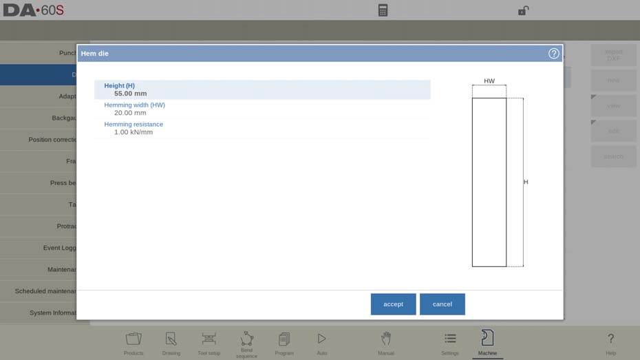
Altura
Altura total da ferramenta. Importante: este valor de altura será usado no cálculo da profundidade da dobra.
Largura da bainha
A largura da ferramenta a ser programada.
Resistência à bainha
Força máxima permitida na ferramenta durante a bainha.
Após inserir esses valores típicos, você pode criar o desenho da ferramenta com os recursos de desenho. O desenho de um perfil de ferramenta é feito inserindo valores de ângulo e comprimento de linha. No Modo Máquina DELEM DA-66S, as ferramentas de desenho por toque também estão disponíveis, assim como no método de desenho de produto.
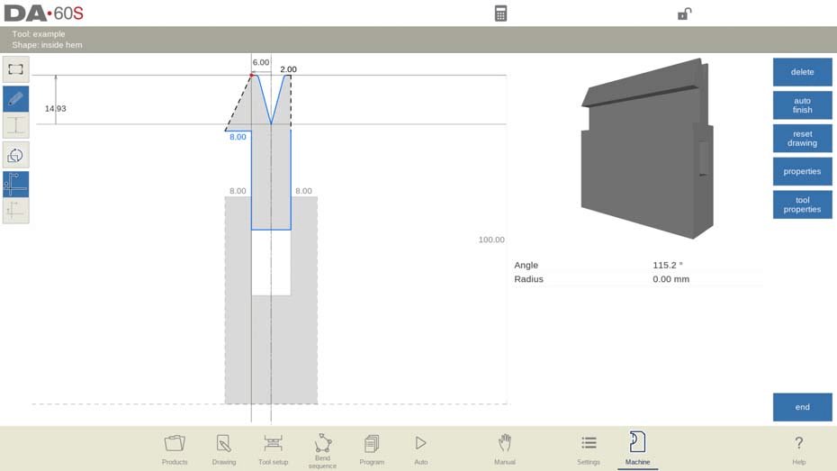
Matriz de dobra da bainha interna
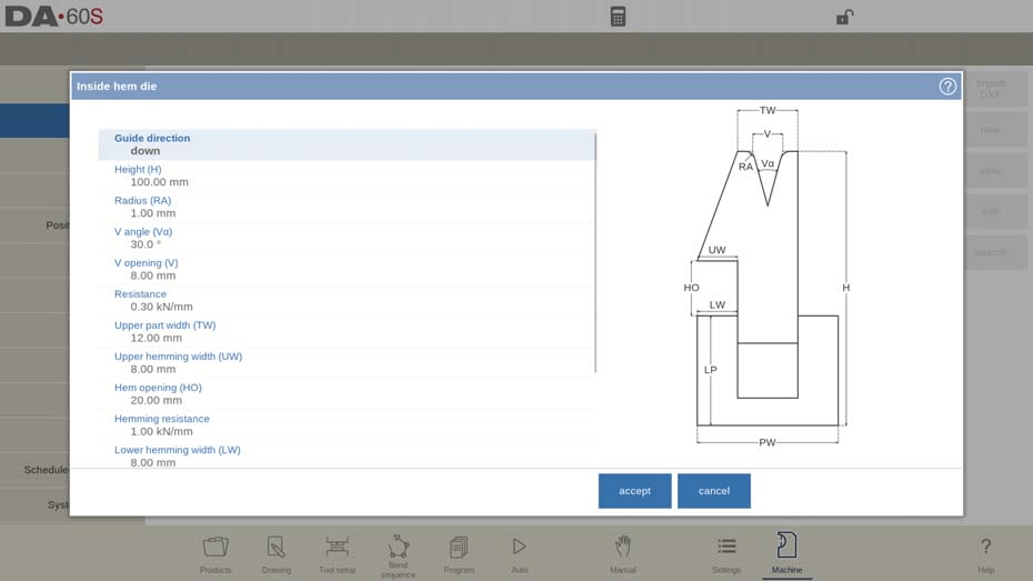
Direção do guia
Define a construção mecânica da matriz da bainha interna.
Altura
Altura total da ferramenta. Importante: este valor de altura será usado no cálculo da profundidade da dobra.
Raio
O raio das bordas da abertura em V.
ângulo V
O ângulo do dado.
Abertura em V
A abertura em V do dado.
Parte inferior em V
Aqui com os diferentes fundos possíveis dentro da abertura em V pode-se definir:
• 'Padrão' é um ângulo agudo na parte inferior do dado.
• 'Redondo' é um fundo de matriz com um raio a ser programado com o parâmetro 'Raio interno'.
• 'Plano' é um fundo de matriz plano com uma determinada dimensão a ser definida com o parâmetro 'Largura do fundo'.
Resistência
Força máxima permitida na ferramenta.
Largura da parte superior
A largura da parte superior do dado.
Largura da bainha superior
A largura do segmento na parte superior da matriz usada para a ação de bainha.
Abertura da bainha
Altura de abertura da matriz no estado aberto para colocar o produto com a bainha dobrada.
Resistência à bainha
Força máxima permitida na ferramenta durante a bainha.
Largura da bainha inferior
A largura do segmento na parte inferior da matriz usada para a ação de bainha.
Largura da parte inferior
A largura da parte inferior do dado.
Altura da parte inferior
A altura da parte inferior do dado.
Tipo de matriz de bainha interna
Este modo permite que você selecione modos de operação específicos adaptados a diversas matrizes de bainha interna, otimizando seu fluxo de trabalho.
- Matriz aberta com mola
Esta matriz utiliza uma mola interna para iniciar em uma posição elevada. Durante a pré-dobragem, a chapa é colocada sobre a matriz aberta, permitindo que o cálculo atinja o ângulo desejado. A altura da bitola traseira é ajustada para corresponder a essa posição aberta. Para a bainha, o produto pré-dobrado é posicionado na abertura da bainha da matriz, permitindo cálculos precisos que consideram o dobro da espessura da chapa para um acabamento de bainha perfeito. Você também pode programar parâmetros adicionais de abertura da bainha como um deslocamento.
- Matriz aberta e travada
A operação padrão trava esta matriz em uma posição alta para ângulos típicos de dobra e pré-dobra. Para habilitar o recurso de bainha, remova o mecanismo de trava, permitindo transições suaves dentro do Modo Máquina DELEM DA-66S.
- Matriz normalmente fechada
Esta matriz fica em uma posição fechada e baixa para ângulos normais de dobra e pré-dobra, e deve ser ativada para obter a ação de bainha.
Adaptar a descompressão
Para permitir a adição do valor de abertura da bainha à distância de descompressão.
não: não foi adicionado de forma alguma.
sim: adicionado para dobras de ar e dobras de bainha.
curva de ar: adicionado somente para curvas de ar (disponível somente para matrizes de bainha abertas por mola).
Depois de inserir esses valores típicos, você pode criar o desenho da ferramenta com os recursos de desenho.
O desenho de um perfil de ferramenta é feito inserindo valores de ângulo e comprimento de linha. As ferramentas de desenho por toque também estão disponíveis, assim como no método de desenho de produto.
Importação DXF (disponível somente quando a opção DXF estiver instalada)
O formato de uma matriz de bainha interna também pode ser carregado por meio da função opcional de importação DXF. Para a importação de uma matriz de bainha interna, é importante que o corpo (parte inferior) da matriz esteja na camada 0 do desenho DXF e a parte móvel (parte superior) esteja em uma camada diferente.
Se esta camada for chamada de "bainha interna", o importador pode selecionar automaticamente o tipo de ferramenta correto; caso contrário, a seleção terá que ser feita manualmente. Ambas as partes no DXF precisam ser contornos fechados.
Ar + bainha dobrada em U
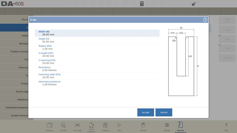
Largura
A largura da ferramenta a ser programada.
Altura
Altura total da ferramenta. Importante: este valor de altura será usado no cálculo da profundidade da dobra.
Raio
O raio das bordas da abertura em U.
Altura U
A altura da abertura em U da matriz.
Abertura em U
A largura da abertura em U da matriz.
Resistência
Força máxima permitida na ferramenta.
Largura da bainha
A largura frontal da matriz, usada como suporte para a dobra da bainha.
Resistência à bainha
Força máxima permitida na ferramenta durante a bainha.
Após inserir esses valores típicos, você pode criar o desenho da ferramenta com os recursos de desenho. O desenho de um perfil de ferramenta é feito inserindo valores de ângulo e comprimento de linha. As ferramentas de desenho por toque também estão disponíveis, assim como no método de desenho de produto.
Matriz Multi V
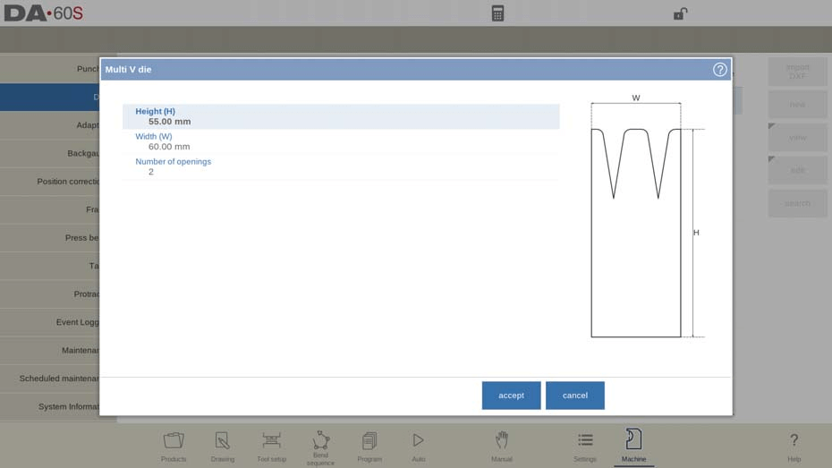
Altura
Altura total da ferramenta. Importante: este valor de altura será usado no cálculo da profundidade da dobra.
Largura
A largura da ferramenta a ser programada.
Número de vagas
Número de aberturas em V ou U.
Propriedades de abertura U/V
Após especificar o número de aberturas V ou U da ferramenta, os recursos específicos da ferramenta devem ser programados em Propriedades quando a abertura V ou U for selecionada.
As propriedades de cada abertura em U ou V podem ser programadas. A resistência da ferramenta pode ser programada de forma geral ou específica.
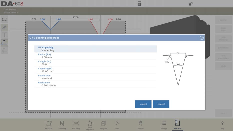
Abertura U/V
Tipo de abertura em V ou U.
Raio
O raio das bordas da abertura em V.
ângulo V
O ângulo do dado.
Abertura em V
A abertura em V do dado.
Parte inferior em V
Aqui com os diferentes fundos possíveis dentro da abertura em V pode-se definir:
• 'Padrão' é um ângulo agudo na parte inferior do dado.
• 'Redondo' é um fundo de matriz com um raio a ser programado com o parâmetro 'Raio interno'.
• 'Plano' é um fundo de matriz plano com uma determinada dimensão a ser definida com o parâmetro 'Largura do fundo'.
Resistência
Força máxima permitida na ferramenta, especificamente para esta abertura em V ou U. Caso seja igual para todos, nenhuma resistência deve ser preenchida. O valor programado em Propriedades da Ferramenta servirá.
Após inserir os valores, use o Modo Máquina DELEM DA-66S para desenhar perfis de ferramentas.

Vario V die (disponível somente se um sistema Vario-V estiver presente)
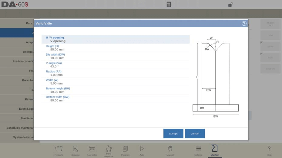
Abertura U/V
Ao utilizar o Modo Máquina DELEM DA-66S, você pode especificar o tipo de abertura U ou V.
Altura
A altura total da ferramenta é crucial, pois afeta o cálculo da profundidade da dobra, incluindo a parte inferior de uma matriz Vario V. Configurar isso com precisão no Modo Máquina DELEM DA-66S é necessário para precisão.
Largura da matriz
Neste modo, você pode definir a largura de um único lado do Vario V, que corresponde à metade da largura total da matriz. A configuração correta garante dobras precisas.
Ângulo V
Você pode ajustar metade do ângulo V no Modo Máquina DELEM DA-66S, permitindo controle preciso sobre os ângulos de curvatura.
Raio
O raio das bordas de abertura em U ou V é outro parâmetro configurável. Garantir configurações precisas de raio contribui para a qualidade e a precisão das dobras.
Largura
Esta configuração envolve a largura de um ângulo em V para um único lado do Vario em V, representando metade da abertura mínima em V.
Altura e largura da parte inferior
Esses parâmetros incluem as dimensões da parte inferior do dado.
Após inserir esses valores, você pode criar o desenho da ferramenta utilizando os recursos de desenho do Modo Máquina do DELEM DA-66S. Isso envolve a inserção de valores específicos de ângulo e comprimento de linha enquanto utiliza ferramentas de desenho por toque, assim como os métodos de desenho de produto. Esse processo simplificado garante que suas operações de usinagem sejam eficientes e precisas.

Propriedades da ferramenta
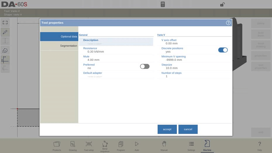
No Modo Máquina DELEM DA-66S, a configuração das propriedades da ferramenta é essencial para alcançar precisão nas operações de prensa dobradeira. Este modo oferece uma variedade de configurações para ajustar as características da sua ferramenta e obter o desempenho ideal.
- Descrição
Cada ferramenta pode ser nomeada ou descrita com até 25 caracteres. Essa descrição é inserida inicialmente e pode ser ajustada conforme necessário. Ela aparece na visão geral da ferramenta na biblioteca, facilitando a identificação de cada ferramenta configurada no Modo Máquina do DELEM DA-66S.
- Resistência
Este parâmetro especifica a força máxima permitida na ferramenta. A configuração correta da resistência é fundamental no Modo Máquina DELEM DA-66S para evitar sobrecarga e possíveis danos.
- Mudo
A distância de silenciamento é o ponto acima da folha onde ocorre uma mudança de velocidade. Ajustar esta configuração no Modo Máquina do DELEM DA-66S ajuda a otimizar a transição entre diferentes velocidades da ferramenta para uma operação mais suave.

- Deslocamento do eixo V
Esse deslocamento é responsável por quaisquer diferenças de largura entre a abertura em V do seu sistema Vario V atual e o sistema com o qual a máquina foi inicialmente comissionada e calibrada.
- Posições Discretas
No caso de um sistema Vario-V analógico, você pode especificar se a abertura em V pode assumir qualquer valor ou ser restrita a intervalos fixos.
- Abertura mínima em V
Este parâmetro define a menor abertura em V disponível na configuração de posição discreta.
- Tamanho do passo e número de passos
Essas configurações dizem respeito ao tamanho do intervalo e ao número total de valores possíveis de abertura V quando posições discretas são usadas.
Importação DXF (disponível somente quando a opção DXF estiver instalada)
O formato de uma matriz Vario V também pode ser carregado por meio da função de importação DXF opcional.
Para o Modo Máquina DELEM DA-66S, certifique-se de que o corpo da matriz Vario V esteja na camada 0 do seu arquivo DXF. Coloque as peças móveis em uma camada separada, idealmente chamada de "Vario V", para seleção automática. Ambas devem ser contornos fechados.
Matriz de bainha interna multi-V

Altura (H)
Altura total da ferramenta. Importante: este valor de altura será usado no cálculo da profundidade da dobra.
Largura da parte superior (TW)
A largura da parte superior do dado.
Número de vagas
Número de aberturas em V ou U.
Ângulo da bainha (Ha)
Ângulo da unidade de bainha.
Largura da bainha superior (UW)
A largura do segmento na parte superior da matriz usada para a ação de bainha.
Abertura da bainha (HO)
Altura de abertura da matriz no estado aberto para colocar o produto com a bainha dobrada.
Resistência à bainha
Força máxima permitida na ferramenta durante a bainha.
Largura da bainha inferior (LW)
A largura do segmento na parte inferior da matriz usada para a ação de bainha.
Largura da parte inferior (PW)
A largura da parte inferior do dado.
Altura da parte inferior (LP)
A altura da parte inferior do dado.
Tipo de matriz de bainha interna
- Matriz aberta com mola
Este tipo de matriz possui uma mola interna que posiciona a matriz inicialmente para cima. No Modo Máquina DELEM DA-66S, para pré-dobramento, a chapa é colocada sobre a matriz aberta. O modo máquina também calcula a altura da bitola traseira, utilizando o nível da matriz aberta para o posicionamento correto. Para bainha, o produto pré-dobrado é posicionado na abertura da bainha da matriz, com os cálculos de profundidade considerando o dobro da espessura da chapa. É possível programar um parâmetro adicional para a abertura da bainha para ajustes adicionais.
Matriz aberta e travada
Nesta configuração, a matriz é travada em uma posição alta, adequada para dobra normal e pré-dobra. Para usar a função de bainha no Modo Máquina DELEM DA-66S, o mecanismo de trava deve ser removido, habilitando a função de bainha.
Matriz normalmente fechada
Com este tipo de matriz, a posição padrão é fechada e baixa, projetada para dobras regulares. A ativação é necessária para realizar operações de bainha ao usar o Modo Máquina DELEM DA-66S.
Adaptar a descompressão
Para permitir a adição do valor de abertura da bainha à distância de descompressão.
não: não foi adicionado de forma alguma.
sim: adicionado para dobras de ar e dobras de bainha.
curva de ar: adicionado somente para curvas de ar (disponível somente para matrizes de bainha abertas por mola).
Propriedades de abertura U/V
Após especificar o número de aberturas V ou U da ferramenta, os recursos específicos da ferramenta devem ser programados em Propriedades quando a abertura V ou U for selecionada.
As propriedades de cada abertura em U ou V podem ser programadas. A resistência da ferramenta pode ser programada de forma geral ou específica.
Abertura U/V
Tipo de abertura em V ou U.
Raio
O raio das bordas da abertura em V.
ângulo V
O ângulo do dado.
abertura
A abertura em V do dado.
Parte inferior em V
Com isso, é possível definir os diferentes fundos possíveis dentro da abertura em V:
• 'Padrão' é um ângulo agudo na parte inferior do dado.
• 'Redondo' é um fundo de matriz com um raio a ser programado com o parâmetro 'Raio interno'.
• 'Plano' é um fundo de matriz plano com uma determinada dimensão a ser definida com o parâmetro 'Largura do fundo'.
Resistência
Força máxima permitida na ferramenta, especificamente para esta abertura em V ou U. Caso seja igual para todos, nenhuma resistência deve ser preenchida. O valor programado em Propriedades da Ferramenta servirá.
Importação DXF (disponível somente quando a opção DXF estiver instalada)
O formato de uma bainha interna com vários Vs também pode ser carregado por meio da função de importação DXF opcional.
Matriz para bainha de batente de porta
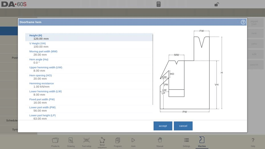
Altura (H)
Altura total da ferramenta. Importante: este valor de altura será usado no cálculo da profundidade da dobra.
Altura V (VH)
A altura da unidade de bainha. Importante: este valor de altura será usado para a operação de bainha.
Largura da parte móvel (MW)
A largura da unidade de bainha/parte móvel da matriz.
Ângulo da bainha (Ha)
Ângulo da unidade de bainha.
Largura da bainha superior (UW)
A largura do segmento na parte superior da matriz usada para a ação de bainha.
Abertura da bainha (HO)
Altura de abertura da matriz no estado aberto para colocar o produto com a bainha dobrada.
Resistência à bainha
Força máxima permitida na ferramenta durante a bainha.
Largura da bainha inferior (LW)
A largura do segmento na parte inferior da matriz usada para a ação de bainha.
Largura de peça fixa (FW)
A largura da parte fixa do dado.
Largura da parte superior
A largura da parte superior do dado.
Largura da parte inferior (PW)
A largura da parte inferior do dado.
Altura da parte inferior (LP)
A altura da parte inferior do dado.
Tipo de matriz de bainha interna
Para os diferentes tipos de matrizes de bainha interna disponíveis, é possível selecionar o modo de operação específico.
Adaptar a descompressão
Para permitir a adição do valor de abertura da bainha à distância de descompressão.
não: não foi adicionado de forma alguma.
sim: adicionado para dobras de ar e dobras de bainha.
curva de ar: adicionado somente para curvas de ar (disponível somente para matrizes de bainha abertas por mola).
Propriedades de abertura em V
Dentro das propriedades da abertura em V, detalhes podem ser programados.
Raio
O raio das bordas da abertura em V.
ângulo V
O ângulo do dado.
Abertura em V
A abertura em V do dado.
Parte inferior em V
Aqui com os diferentes fundos possíveis dentro da abertura em V pode-se definir:
• 'Padrão' é um ângulo agudo na parte inferior do dado.
• 'Redondo' é um fundo de matriz com um raio a ser programado com o parâmetro 'Raio interno'.
• 'Plano' é um fundo de matriz plano com uma determinada dimensão a ser definida com o parâmetro 'Largura do fundo'.

Importação DXF (disponível somente quando a opção DXF estiver instalada)
O formato de uma bainha de batente de porta também pode ser carregado por meio da função de importação DXF opcional.
Wingbend morre
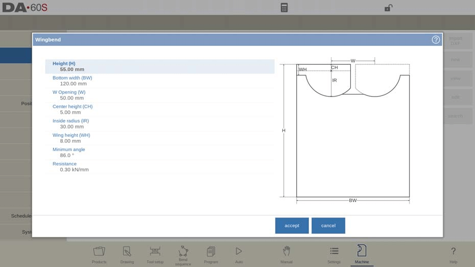
No Modo Máquina do DELEM DA-66S, a configuração das propriedades da ferramenta, como matrizes de curvatura de asa, garante a precisão. Os principais parâmetros incluem a distância do ponto de rotação até o topo da matriz e o raio da asa. Ajuste essas configurações para obter o desempenho ideal.
Altura (H)
Altura total da ferramenta, incluindo as possíveis asas extensíveis. Importante: este valor de altura será usado no cálculo da profundidade da dobra.
Largura inferior (BW)
A largura da ferramenta a ser programada.
Abertura W (W)
Distância entre os pontos de rotação.
Altura central (CH)
Altura da asa acima do ponto de rotação interno.
Raio interno (IR)
Raio da asa a partir do seu ponto de rotação interno.
Altura da asa (WH)
A altura da asa dentro da definição de altura da ferramenta (parte da altura da ferramenta em movimento).
Ângulo mínimo
Menor ângulo que pode ser dobrado com esta ferramenta de curvatura de asa.
Resistência
Força máxima permitida na ferramenta.
Propriedades de curvatura de asa
- Largura (L)
Distância entre os pontos de rotação.
- Altura central (CH)
Altura da asa acima do ponto de rotação interno.
- Raio interno (IR)
Raio da asa a partir do seu ponto de rotação interno.
- Lacuna (G)
Distância entre as duas asas.
- Largura da asa (WW)
Largura do topo da asa.
- Altura da asa (WH)
A altura da asa dentro da definição de altura da ferramenta (parte da altura da ferramenta em movimento).
- Altura inferior (BH)
Altura da parte do meio representando a profundidade da abertura em V.
- Ângulo mínimo
Menor ângulo que pode ser dobrado com esta ferramenta de curvatura de asa.
Importação DXF (disponível somente quando a opção DXF estiver instalada)
O formato de uma matriz de curvatura de asa também pode ser carregado por meio da função de importação DXF opcional.
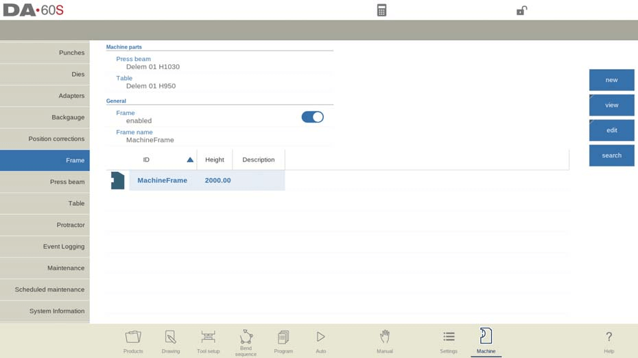
Quadro
As propriedades da ferramenta no Modo Máquina do DELEM DA-66S são cruciais para a configuração das geometrias da máquina, incluindo a viga de prensa, a mesa e as estruturas laterais. Você pode selecionar e configurar esses elementos, além de programar a identificação da máquina. Essa configuração afeta a tela de simulação, auxiliando na programação gráfica e na detecção de colisões.
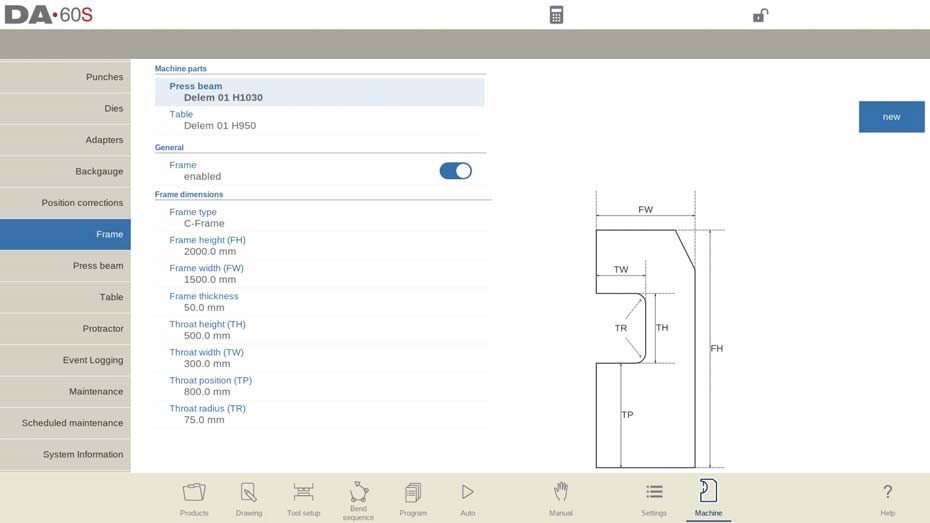
Na parte superior da tela, é possível selecionar as possíveis peças da máquina. As peças selecionadas são utilizadas quando uma nova configuração de ferramenta é programada.
Seleção de feixe de pressão
Selecione a viga de prensa da máquina relevante.
Configuração da tabela
Selecione a tabela de máquina relevante.
Ajustes de quadro
As estruturas laterais da máquina desempenham um papel na sequência geral de dobra e na acomodação da largura do produto. Dependendo do projeto da sua máquina, você pode optar por desabilitar a exibição das estruturas nas simulações, especialmente se as estruturas estiverem fora da zona de dobra e não afetarem a detecção de colisão. Normalmente, este parâmetro é habilitado por padrão.
Opções de tipo de quadro
Embora a estrutura padrão seja uma estrutura em C, você pode selecionar uma estrutura em O, se disponível. A estrutura em O proporciona uma configuração simétrica, influenciando o processo de dobra de ambos os lados da mesa.
Dimensões da estrutura
Ajuste a altura, a largura e a espessura da estrutura. Essas dimensões afetam a integridade estrutural da máquina e a capacidade da sequência de dobra.
Especificações da Garganta
Configure a altura, a largura, a posição e o raio da garganta para atender aos requisitos do espaço de trabalho. Esses parâmetros definem a área do espaço de trabalho, afetando o posicionamento e a manobra da chapa metálica durante a dobra.
Editor de contornos em C
Alternativamente, a forma do quadro C também pode ser desenhada como um contorno. No editor de contornos, os detalhes do contorno do quadro C podem ser desenhados em detalhes. Partindo da forma básica, é possível desenhar o quadro como ele está; por exemplo, raios podem ser adicionados entre as linhas, bem como nas próprias linhas.
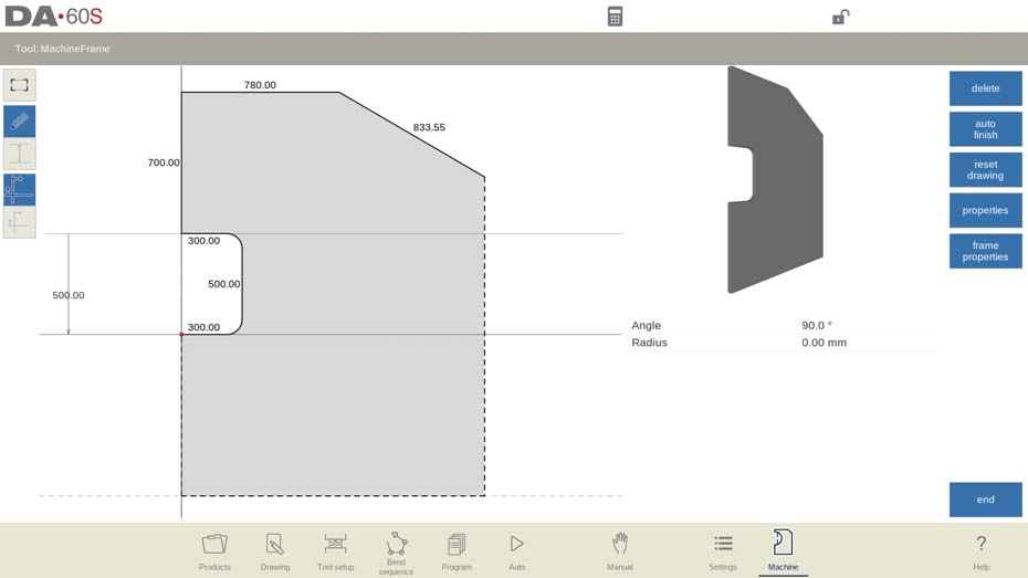
Ao utilizar esta função de programação gráfica ela substitui o quadro parametrizado
programação.
Adaptadores
No Modo Máquina DELEM DA-66S, configurar as propriedades da ferramenta é essencial para otimizar as operações da prensa dobradeira. Aqui está uma visão geral simplificada das principais configurações que você pode gerenciar:
Configuração do adaptador
Adaptadores de ferramentas, tanto superiores quanto inferiores, podem ser habilitados e programados através do Modo Máquina DELEM DA-66S. Você pode designar um adaptador padrão para ser selecionado automaticamente durante a configuração da ferramenta, garantindo a consistência nas operações.
Detalhes do adaptador
A configuração inicial requer a especificação de parâmetros básicos a partir de um modelo, seguidos de um desenho detalhado, semelhante a punções ou matrizes. Os principais aspectos incluem:
- Forma: Escolha entre formatos básicos de adaptadores, como adaptadores de punção para a viga de prensa ou adaptadores de matriz para a mesa.
- ID e descrição: Atribua um identificador e uma descrição exclusivos, cada um com até 25 caracteres.
- Tipo de suporte: Defina se os adaptadores são 'montados na cabeça' ou 'montados no ombro' para minimizar problemas de precisão na altura da ferramenta e no posicionamento do eixo Y.
- Resistência: Defina a força máxima que o adaptador pode suportar. Um valor zero indica que não há verificação de resistência.
Recursos avançados
- Importação DXF: Se disponível, importe formas adaptadoras usando a função DXF para maior precisão.
- Ponto de montagem: Identifique os pontos de conexão na viga ou mesa da prensa, cruciais para o alinhamento da ferramenta e do adaptador.
Configurações padrão do adaptador
Combinações de adaptadores de ferramentas usadas com frequência podem ser definidas como padrões, permitindo a configuração automática sempre que a ferramenta for selecionada, simplificando assim o processo de configuração.
Ao configurar precisamente as propriedades da ferramenta no Modo Máquina DELEM DA-66S, os usuários podem aumentar a eficiência e manter altos padrões de qualidade em tarefas de metalurgia.
Batente traseiro
Com as dimensões do pino do batente traseiro, o movimento do eixo R e o movimento do eixo X relacionado são levados em consideração. Além disso, a colisão entre a peça e o batente traseiro é calculada usando as dimensões.

Posição padrão de repouso
Esta é a posição de espera padrão caso uma posição de espera precise ser usada durante o cálculo automático da sequência de dobra, por exemplo, caso a posição do eixo X esteja fora do intervalo permitido ou seja maior que o 'Limite de recuo de espera'; ela não é usada ao selecionar um nível de espera manualmente.
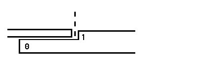
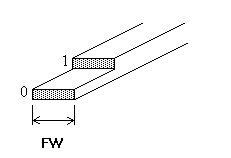
Significado dos números lay-on:
Deitado = 0
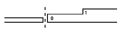
Deitado = 1
Deslocamento do medidor R
Um valor de deslocamento para o eixo R pode ser definido se o limitador traseiro estiver posicionado contra a borda da folha e a posição do eixo X estiver fora da zona de segurança da matriz.
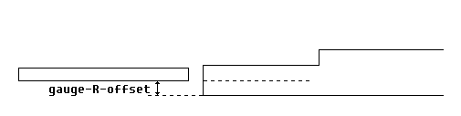
Um valor negativo indica uma posição mais baixa do batente traseiro. Este deslocamento é válido apenas para a posição 0 do batente.
Largura do dedo
A largura do pino do batente traseiro. Disponível somente quando os eixos Z automáticos estiverem instalados.
Raio do dedo
Raio da ponta do batente traseiro. Um valor 0 significa que não há raio. Disponível somente quando os eixos Z automáticos estiverem instalados.
No Modo Máquina do DELEM DA-66S, um aspecto essencial é a configuração do batente traseiro, onde você pode editar dimensões e posições para obter um desempenho ideal.
Posições do batente traseiro
No Modo Máquina do DELEM DA-66S, você pode configurar até quatro posições de batente traseiro. Modificar este parâmetro atualiza a geometria dos dedos, permitindo a programação específica das dimensões dos dedos.
Dimensões do dedo e do medidor
- Altura do dedo (FH): Ajuste a espessura da ponta do primeiro dedo do batente traseiro para um posicionamento preciso.
- Comprimento do dedo (FL): Defina o comprimento do nível de assentamento inicial para atender às necessidades do seu projeto.
- Altura do medidor (H1/H3/H4): Configure as alturas para vários níveis de assentamento para garantir alinhamento preciso.
- Comprimento do calibre (L2/L3): Determine o comprimento dos níveis de apoio adicionais para maior alcance.
- Altura do medidor (H2): Ajuste a altura na base do medidor.
- Comprimento do calibre (L1): Defina o comprimento no nível do dedo inferior do medidor.
Biblioteca de dedos do batente traseiro
O modo de máquina DELEM DA-66S oferece recursos de configuração robustos para propriedades de ferramentas, com foco específico em dedos de batente traseiro.
Biblioteca dos Dedos
Vários conjuntos de dedos de batente traseiro podem ser programados e exibidos em uma biblioteca no DELEM DA-66S. Essa configuração também permite a ativação do banco de dados para configurações especiais de dedos, a fim de atender a diferentes requisitos do produto. Ao selecionar um produto, é crucial garantir que os dedos correspondentes programados por CNC sejam selecionados na máquina.
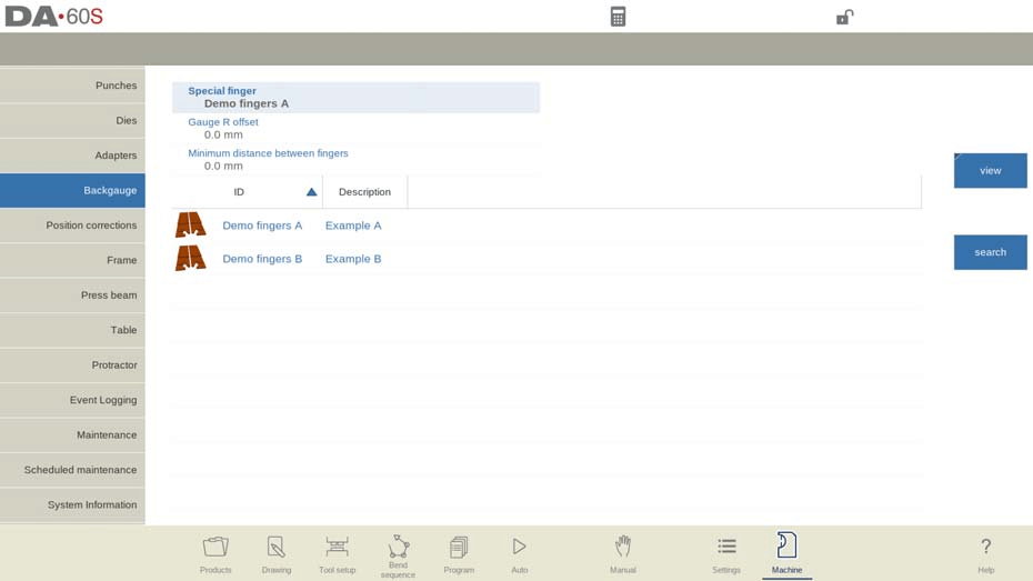
Configurações especiais de dedos
Nome (ID) do conjunto de pinos do batente traseiro selecionado. Toque para modificar ou selecionar na biblioteca de pinos do batente traseiro.
Distância mínima
Uma consideração crítica no Modo Máquina do DELEM DA-66S é a distância mínima entre os dedos, que pode ser definida para evitar interferências. Se definido como 0, este parâmetro é ignorado. A exclusão de todos os conjuntos de dedos reativa as definições de dedos parametrizadas padrão.
Deslocamento X
Ao editar um dedo especial na biblioteca, o parâmetro de deslocamento X está disponível. Ele representa a diferença de comprimento entre a frente do dedo selecionado e o dedo original usado durante a calibração da máquina.
Correções de posição
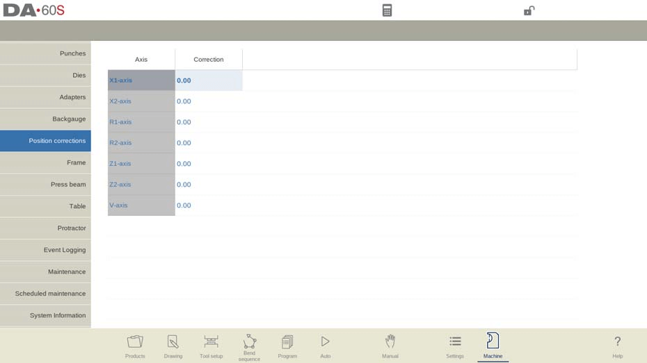
Correção de posição
Quando a posição real do eixo mecânico não corresponde ao valor exibido, é possível corrigir a posição com este parâmetro. Programe a diferença calculada.
Exemplo:
– Quando o valor programado e exibido = 250 e o valor real da posição mecânica = 252, o parâmetro de correção = -2.
– Quando o valor programado e exibido = 250 e o valor real da posição mecânica = 248, o parâmetro de correção = +2.
Correções de posição estão disponíveis para todos os eixos auxiliares.
As correções de posição devem ser usadas apenas temporariamente. Caso as posições da máquina tenham mudado após o comissionamento ou manutenção, as posições dos eixos podem ser corrigidas. Em situações normais, essas correções devem ser 0.
Pressione o feixe
Esta configuração envolve a configuração da geometria da máquina para detecção de colisão com o produto e peças da máquina.
Geometria de Máquina e Detecção de Colisão
Você pode programar a geometria da máquina como um perfil para detectar potenciais colisões. Utilitários especiais adicionados à máquina podem ser modelados e considerados nos cálculos de colisão. Normalmente, uma única forma de máquina é programada. As formas são desenhadas de forma semelhante a punções e matrizes, com o lado direito indicando a posição da bitola traseira da máquina.
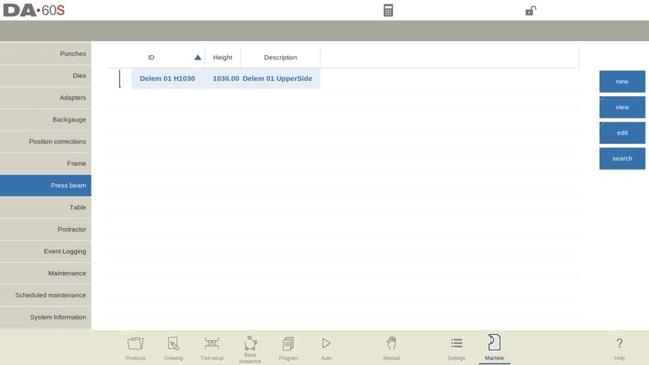
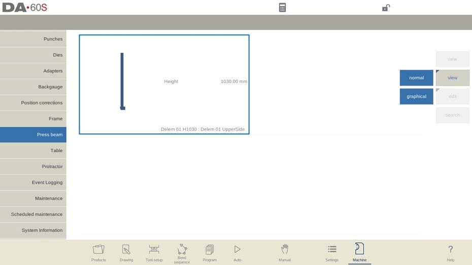
Visualização e edição de peças da máquina
Para visualizar detalhes, use a opção "Visualizar" e selecione "Gráfico" na aba da biblioteca. Para criar uma nova peça de máquina, toque em "Editar" e depois em "Adicionar".
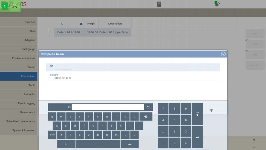
Você precisará inserir:
- EU IA: Um nome ou número exclusivo (até 25 caracteres) para identificar a peça da máquina.
- Descrição: Uma breve descrição ou nome (até 25 caracteres).
- Altura: Altura total da parte da máquina.
Resistência do porta-ferramentas
Esta configuração define a força máxima permitida no porta-ferramentas. Um valor 0 significa que não há verificação de resistência.
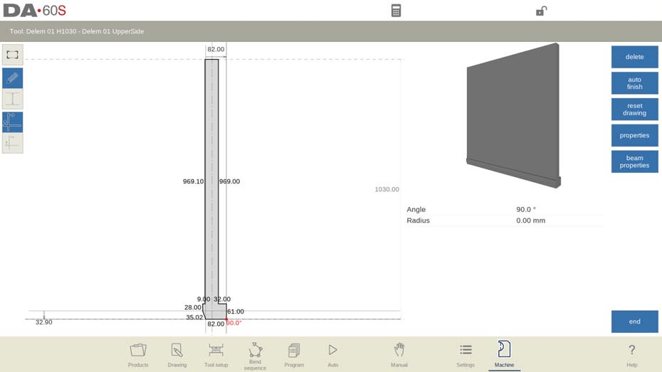
Configuração do feixe de pressão
Para a viga de prensa, a altura é a medida quando a parte móvel do lado superior está em seu ponto morto superior. Após inserir os parâmetros básicos, o editor de desenho permitirá que você esboce ou defina a peça inserindo os comprimentos e as direções dos lados.
Pontos de importação e montagem DXF
Se a importação DXF opcional estiver disponível, as formas podem ser carregadas de arquivos DXF. Os pontos de montagem, onde punções ou adaptadores são colocados, podem ser programados opcionalmente e indicados no desenho.
Mesa
Ao configurar o Modo Máquina do DELEM DA-66S, as propriedades da ferramenta desempenham um papel vital na otimização das operações da prensa dobradeira. Esta aba permite programar a geometria da máquina para a mesa, auxiliando na detecção de colisões e garantindo um funcionamento suave com utilitários adicionais.

Configuração de peças da máquina
Para adicionar novas peças de máquina, como formas especiais para cálculos de colisão, use a função "Editar" na biblioteca. Cada peça requer um ID, uma breve descrição e uma altura. O ID e a descrição ajudam a identificar a peça, ambos limitados a 25 caracteres. A altura da peça é crucial para definir a geometria da máquina.
Resistência do porta-ferramentas
Defina a força máxima permitida no porta-ferramentas para segurança. Um valor de resistência de 0 significa que não há verificação aplicada pelo Modo Máquina do DELEM DA-66S.
Desenho e Importação
Após inserir os parâmetros básicos, use o editor de desenho para projetar as peças da máquina, seja esboçando ou especificando dimensões. Para formas complexas, utilizar a função de importação DXF pode agilizar o processo, desde que a opção seja instalada.
Pontos de montagem e eixo I
Programe pontos de montagem para a mesa, matriz ou adaptador, indicando onde esses componentes se conectam. A linha divisória do eixo I mostra a divisão entre as seções estática e dinâmica da mesa, essencial para coordenar o movimento com o eixo I. Ajustar a posição padrão do eixo I permite um alinhamento preciso.
Funcionalidade de desenho para ferramentas, adaptadores e formas de máquinas
No Modo Máquina do DELEM DA-66S, a configuração das propriedades da ferramenta é essencial para operações precisas de usinagem. Essa funcionalidade permite que os usuários programem punções, matrizes e adaptadores com precisão, aprimorando a capacidade de prevenção de colisões.
Ao desenhar formas de ferramentas, vários métodos estão disponíveis para obter a configuração desejada. Você pode esboçar a forma inicialmente e ajustar os segmentos ou construí-la passo a passo desde o início. É crucial fechar essas formas, e a função de finalização automática pode ajudar com isso.
A altura programada da ferramenta é essencial para os cálculos de dobra e deve ser cuidadosamente considerada para obter resultados ideais.
Os principais recursos incluem:
- Linhas e ângulos podem receber um raio, auxiliando no detalhamento preciso das formas.
- A funcionalidade de encaixe garante que as linhas e os ângulos se alinhem corretamente com o ambiente ao redor.
- As linhas têm dimensões de comprimento e projeção, que podem ser programadas juntamente com os valores de ângulo. O sistema de controle auxilia ajustando os valores circundantes necessários com base nas informações inseridas pelo usuário.
- Linhas de ajuda auxiliam na medição de distâncias entre pontos, permitindo que os usuários modifiquem os pontos com base na distância desejada. Este recurso pode ser desativado para uma visão desobstruída.
- Ao usar pontos de montagem, o controle evita alterações não intencionais nos detalhes da ferramenta alternando entre pontos de montagem e desenhos.
Esses recursos no Modo Máquina DELEM DA-66S otimizam a configuração da ferramenta, aumentando a precisão e a eficiência em tarefas de modelagem de metal.
Importação DXF para ferramentas, adaptadores e peças de máquinas (disponível apenas quando A opção DXF foi instalada)
No Modo Máquina do DELEM DA-66S, a configuração das propriedades da ferramenta é simplificada com a poderosa função de importação de DXF. Este recurso, acessível na biblioteca de ferramentas, permite importar contornos de arquivos DXF, simplificando a personalização de punções, matrizes, adaptadores e componentes da máquina, como a viga de prensa, a mesa e a estrutura.
Para começar, use o navegador de arquivos para selecionar o arquivo DXF desejado. Você pode ajustar as configurações de conversão, incluindo a seleção de camadas, para atender às suas necessidades, seja focando em camadas específicas ou apenas em informações de contorno.
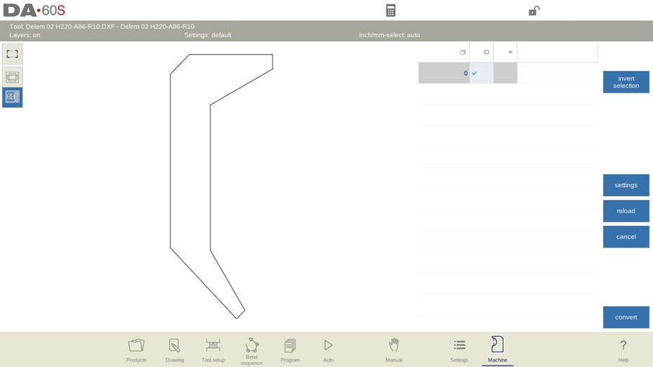
Após selecionar "Converter", você pode selecionar a detecção automática de forma ou designar manualmente a forma e atribuir um ID de nome. O sistema então processa a conversão, apresentando a nova ferramenta no editor de ferramentas. Aqui, você pode definir atributos específicos, como altura da ferramenta e pontos de montagem.
Após a edição, a ferramenta é adicionada à sua biblioteca, pronta para uso e ajustes posteriores, aumentando a flexibilidade e a eficiência em suas operações.
Para ferramentas especializadas com múltiplos contornos, certifique-se de que o corpo principal esteja na camada 0 do desenho DXF. Peças adicionais, como a bainha interna ou as seções da asa, devem estar em camadas distintas, nomeadas de acordo, facilitando a seleção automática do tipo de ferramenta durante a importação. Essa precisão garante que todos os componentes da ferramenta sejam representados com precisão e funcionais.
Transferidor
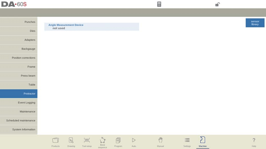
Opções de dispositivos de medição de ângulo:
- Não utilizado: Nenhum dispositivo selecionado.
- Mitutoyo 187-50x: Dispositivo de medição padrão.
- Mit.187-50x U-WAVE: Exibe se um receptor sem fio é detectado na inicialização.
- Mitutoyo 187-50x IBR: Outra opção padrão.
- KEBA KeMes A205: Opção sem fio ativada após detecção.
Esses dispositivos funcionam em modos de produção para fornecer medições de ângulo em tempo real. Ao posicionar o cursor no campo de correção alfa e pressionar o botão de transmissão, o Modo Máquina DELEM DA-66S exibe o ângulo recebido. Pressionar Enter aceita o valor e calcula as correções necessárias.
Correção automática de ângulo:
- Entrada automática corr.α (Desligado): Exibe correções calculadas, exigindo entrada manual pelo operador.
- Entrada automática corr.α (Ligado): Aplica automaticamente correções de ângulos medidos sem entrada manual no controle DA.
Tolerância de ângulo e cálculo:
- Tolerância: Define o desvio máximo permitido entre os ângulos programados e medidos. Desvios excessivos acionam uma mensagem de erro e as correções automáticas não serão aplicadas se os desvios forem muito grandes.
- Cálculo de ângulo: As opções incluem tratar o ângulo medido como um suplemento (180-α) ou o ângulo real do produto (α).
Entender e configurar essas propriedades da ferramenta no Modo Máquina DELEM DA-66S garante um gerenciamento de ângulo preciso e eficiente em suas operações.
Perguntas Frequentes (FAQ)
Que precauções devo tomar ao usar os tipos de matriz de bainha interna no modo de máquina DELEM DA-66S?
Ao utilizar matrizes de bainha interna, é crucial compreender seus modos de operação específicos no Modo Máquina DELEM DA-66S. Por exemplo, decida se deseja usar os tipos de matriz com abertura por mola, aberta e travada ou normalmente fechada, cada uma com seus requisitos de configuração e ativação, para obter as ações de dobra e bainha desejadas.
Posso programar configurações de ferramentas personalizadas no Modo Máquina do DELEM DA-66S?
Sim, o Modo Máquina DELEM DA-66S permite configurar ferramentas personalizadas ajustando parâmetros como altura, ângulo e largura. Isso garante alinhamento e encaixe precisos, aumentando a eficiência e a precisão das suas operações.
Como posso garantir configurações de pressão precisas no Modo Máquina DELEM DA-66S?
Configurações precisas de pressão são vitais para a integridade do material durante a dobra. Use o Modo Máquina DELEM DA-66S para ajustar as configurações de pressão, garantindo que sejam adequadas à espessura do material e às especificações de dobra desejadas para evitar dobras excessivas ou danos.
Conclusão
Em suma, o Modo Máquina DELEM DA-66S oferece um conjunto abrangente de opções de configuração que permitem aos operadores realizar operações de dobra e bainha precisas. Elementos-chave como altura da ferramenta, ângulo, raio e tipos específicos de matriz, incluindo matrizes com abertura por mola, matrizes abertas e travadas e matrizes normalmente fechadas, são componentes essenciais para garantir o desempenho e a precisão ideais da máquina.
Para aproveitar ao máximo os recursos da sua máquina dobradeira e aumentar a eficiência da produção, é crucial configurar essas configurações com precisão. A compreensão e os ajustes adequados levarão a melhores resultados e à minimização de erros em suas tarefas de usinagem.
Para obter mais assistência ou dúvidas sobre a configuração do seu Modo Máquina DELEM DA-66S, entre em contato com nossa equipe para obter orientação especializada. Além disso, não deixe de explorar nossa documentação e recursos para obter insights mais detalhados sobre como maximizar o potencial do seu equipamento.


