


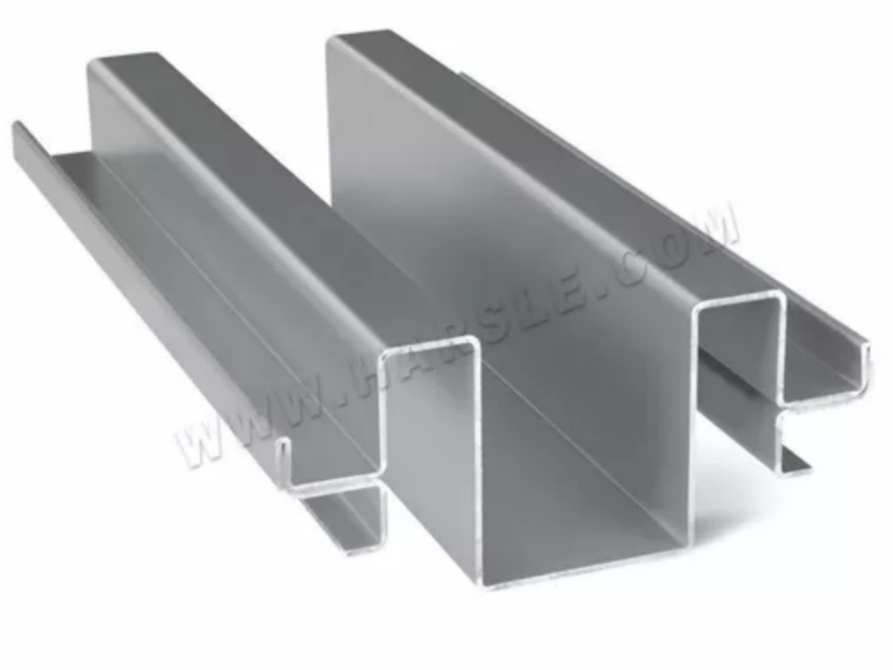
Melhore a precisão da dobra ajustando a configuração e as técnicas da sua prensa dobradeira, garantindo resultados precisos e de alta qualidade sempre.
Descubra estratégias eficazes para melhorar a precisão da dobra. Da configuração correta da prensa dobradeira à otimização de ferramentas, este guia ajudará você a obter dobras consistentes e precisas para resultados superiores. Vamos nos aprofundar nas principais etapas para otimizar seu processo de dobra e garantir maior precisão em cada operação.
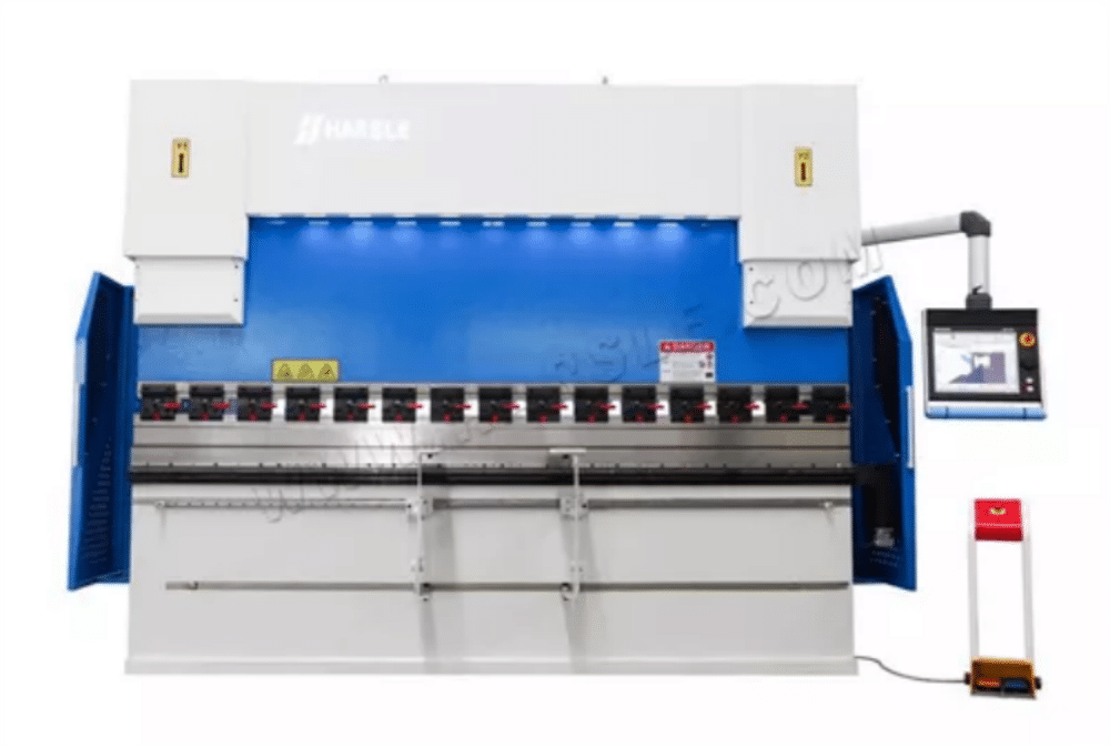
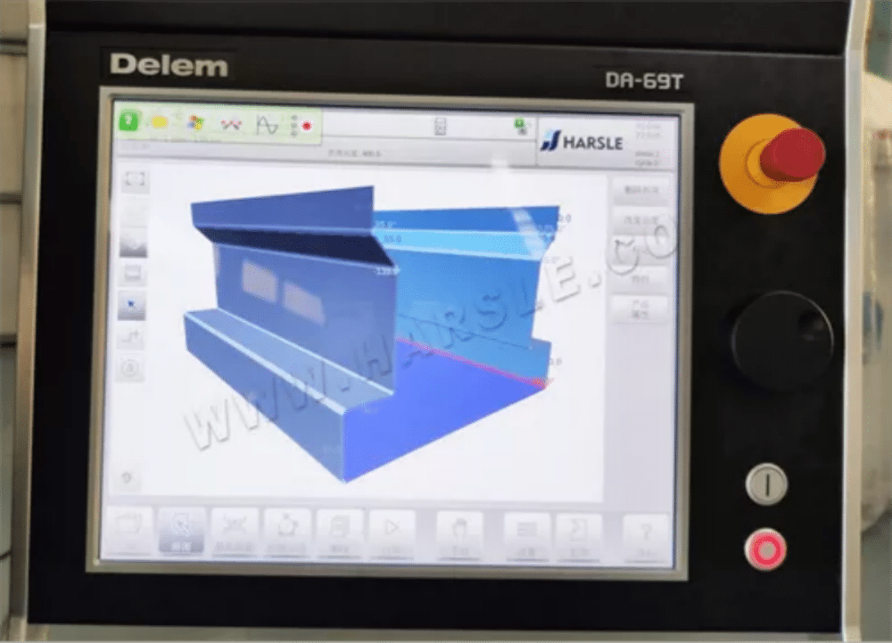
No uso real do máquina de dobrarA precisão da dobra pode apresentar mais ou menos erros. Às vezes, pode ser devido a fatores mecânicos da máquina que não a tornam suficientemente precisa. Também podem ser fatores externos, como ferramentas de dobra, espessura do material da chapa de dobra, etc., e até mesmo fatores de operação humana. Este artigo analisará os fatores que afetam a precisão da dobra sob diversos aspectos e proporá soluções para algumas das situações comuns.
● Fatores comuns
Fatores Mecânicos
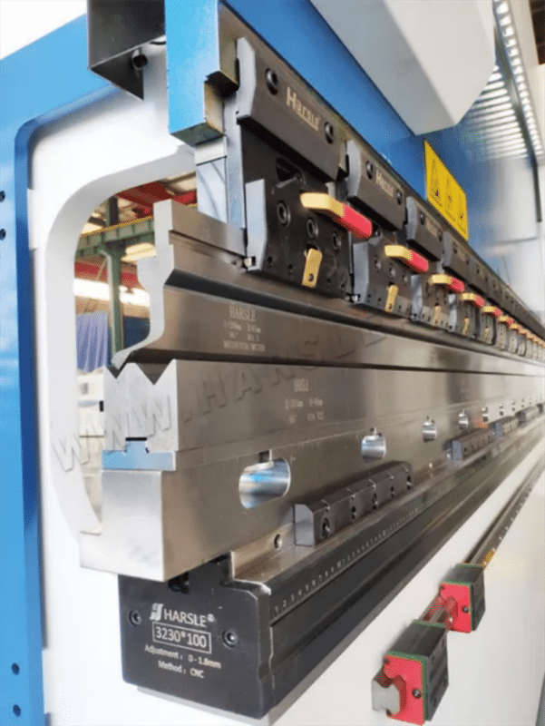
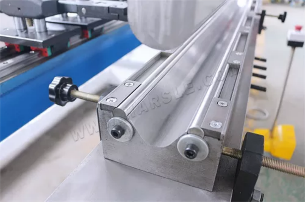
1. máquina de dobrar retidão da boca de fixação do controle deslizante (direção Y e direção X).
2. Precisão de reposicionamento dos controles deslizantes esquerdo e direito e precisão de posicionamento arbitrário.
3. A folga do cursor da máquina de dobrar e do trilho da cremalheira é razoável.
4. A verticalidade e a inclinação interna da estrutura são razoáveis.
5. A conexão entre o cilindro de óleo e o cursor.
6. A resistência e a precisão da estrutura e do controle deslizante.
7. A precisão de reposicionamento do sistema de bloqueio traseiro, a precisão do posicionamento arbitrário (direção X e direção R).
8. Se o sistema de computador está ajustado no local.
9. Se o sistema hidráulico está ajustado no local.
10. Correspondência do sistema hidráulico e ajuste do computador.
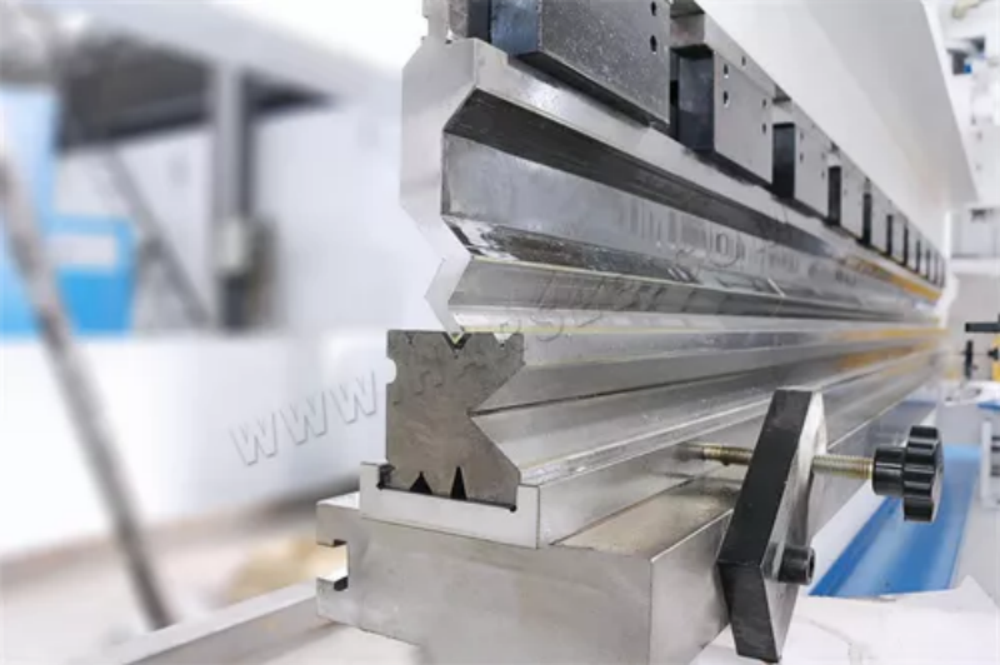
Fatores de mofo
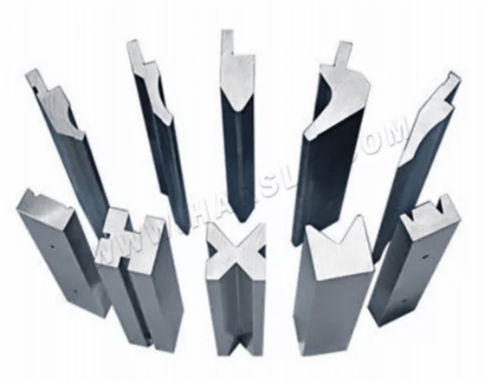
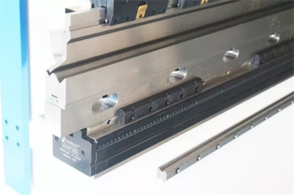
1. Se a precisão dos moldes superior e inferior é exata.
2. A deformação, os danos, o desgaste e outros fenômenos do molde terão impacto em todos os aspectos da dobra e conformação, uma vez constatados, devem ser prontamente relatados para correção.
3. Os moldes superior e inferior do núcleo da faca diferente levarão a um desvio no tamanho da curvatura, a faca deve garantir que esteja no lugar.
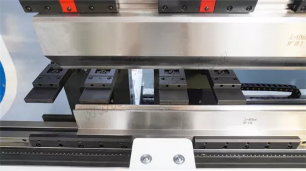
4. Após o batente, o material se move para a esquerda e para a direita, e a distância relativa à matriz inferior muda. O paquímetro pode ser medido pelo ajuste fino do parafuso do batente traseiro.
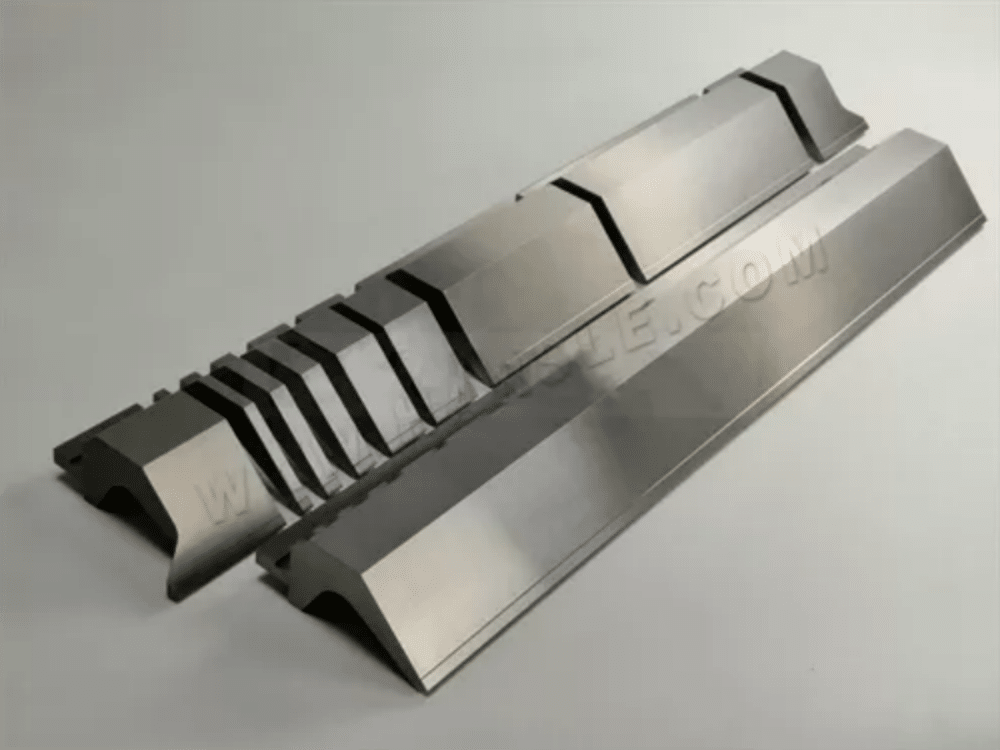
5. Se o dispositivo de compensação da matriz inferior é preciso e se o design da estrutura corresponde.
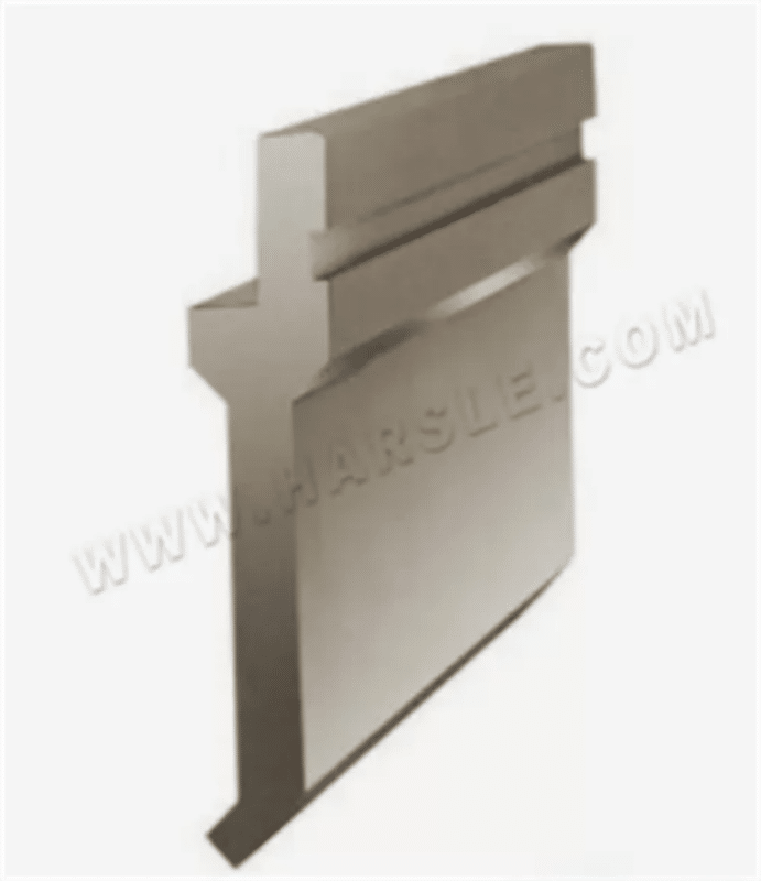
6. A precisão do gabarito da matriz superior deve ser alta.
7. O tamanho da boca em V da matriz inferior e a pressão de dobra são inversamente proporcionais ao comprimento e à espessura da placa. Quanto maior a ranhura em V, menor a pressão necessária. Portanto, o tamanho correto da ranhura em V da matriz inferior deve ser usado de acordo com os regulamentos ao processar peças de trabalho de diferentes espessuras.
8. Em uma extremidade da dobradeira, ou seja, ao processar com carga lateral única, a pressão de dobra é afetada, o que também prejudica a máquina-ferramenta, sendo expressamente proibido. A parte central da máquina deve ser sempre mantida sob pressão durante o alinhamento das ferramentas.
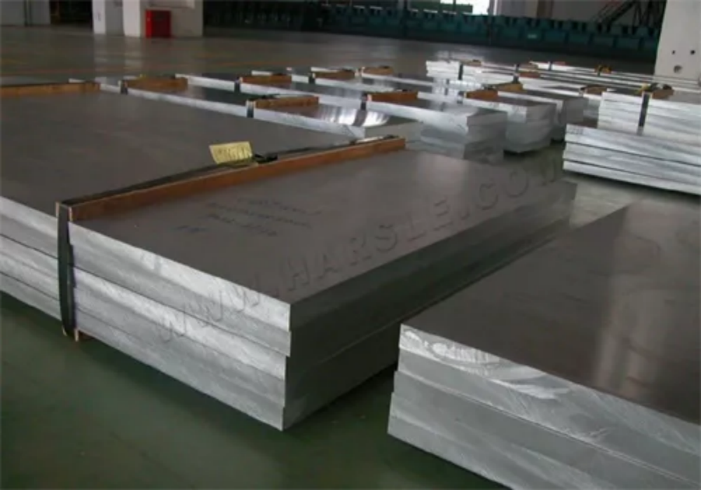
Fatores de material da folha
1. Retilinidade do dado da chapa metálica.
2. A uniformidade da tensão na chapa metálica.
3. A uniformidade da espessura da chapa metálica.
4. Paralelismo insuficiente entre a peça de trabalho e a matriz inferior durante a dobra, e rebote da peça de trabalho após a matriz superior ser pressionada para baixo, afetando as dimensões de dobra.
5. As características e a espessura do material afetarão o ângulo de curvatura, portanto, cada dobra da peça de trabalho deve ser a primeira inspeção e fortalecer a inspeção de amostragem.
Fatores Humanos
1. As pessoas na placa de ferro de flexão empurram para a esquerda e para a direita, o impulso é consistente.
2. O uso do sistema não é ajustado aos erros de dados dentro do sistema.
3. Um ângulo de curvatura não é suficiente quando o tamanho da curvatura secundária for afetado.
4. O erro cumulativo da dobra levará a um aumento no erro dimensional do perfil da peça. Portanto, é particularmente importante garantir a precisão da dobra unilateral.
5. O comprimento e a espessura da peça de trabalho requerem pressões diferentes, e o comprimento e a espessura da chapa são proporcionais à pressão. Portanto, o comprimento e a espessura da peça de trabalho mudam quando a pressão de dobra precisa ser reajustada.
● Noções básicas sobre manutenção de mofo
Os problemas acima podem ser observados, a precisão do molde e o uso da precisão de dobra têm um impacto crucial no uso da máquina de dobra para os possíveis problemas do molde superior e inferior, resumimos os seguintes itens essenciais de manutenção do molde para compartilhar com você.
● Manutenção Básica do Molde
A manutenção contínua do molde deve ser cuidadosa, paciente, passo a passo, sem envolvimento cego. Ao reparar moldes devido a falhas, uma fita de cuidado deve ser fixada ao molde para facilitar a identificação do problema. Abra o molde, verifique a condição do molde com a fita de cuidado, confirme a causa da falha, identifique o problema e limpe o molde antes de desmoldar.
Para estruturas de molde onde a mola de descarga está entre a placa fixa e a placa de descarga e onde a mola de descarga está diretamente em cima do pilar guia interno, a placa de descarga deve ser removida de forma que a placa fique equilibrada e salte para fora.
● Manutenção dos Moldes Superior e Inferior
Ao desmontar os moldes superior e inferior, observe a condição original dos moldes para que possam ser facilmente recuperados durante a montagem subsequente. Ao substituir a matriz superior, tente inserir o bloco de descarga e verifique se a matriz inferior está lisa e se a folga entre o inserto e a matriz inferior é uniforme. Se a matriz superior for encurtada após a afiação e um calço precisar ser adicionado para atingir o comprimento necessário, verifique se o comprimento efetivo da matriz superior é suficiente. Para substituir uma matriz superior quebrada, identifique a causa e verifique se a matriz inferior correspondente apresenta uma borda lascada e se a borda precisa ser retificada. Para montar a matriz superior, verifique se há folga suficiente entre a matriz superior e o bloco ou placa de fixação e, se houver um bloco de prensa, verifique se há margem de movimento. A matriz inferior deve ser colocada horizontalmente e, em seguida, o bloco de ferro plano deve ser colocado na face da matriz inferior e encaixado no lugar com uma haste de latão, sem ser inclinado. Após a montagem, verifique se a superfície inferior do molde está nivelada com a superfície do molde. Após a montagem dos moldes superior e inferior, bem como dos machos, devem ser feitas as verificações necessárias na correia de cuidado para ver se as peças estão encaixadas incorretamente ou invertidas, se o molde inferior e a junta do molde inferior estão invertidos, se o orifício de queda está bloqueado, se as novas peças precisam ser roubadas, se há material suficiente para roubar e se as partes do molde que precisam ser travadas estão travadas firmemente. Preste atenção à confirmação de travamento dos parafusos da placa de extração. Ao travar, os parafusos devem ser travados de dentro para fora com força equilibrada, não travando um determinado parafuso primeiro e depois outro parafuso, para não causar a inclinação da placa de extração, resultando na quebra do molde superior ou na redução da precisão do molde.
● Ajuste da folga do molde
Os furos de posicionamento do núcleo da matriz estão desgastados devido à combinação frequente de núcleos da matriz, resultando em grande folga após a montagem (afrouxamento após a montagem) ou folga irregular (desvio de posicionamento), o que causará má forma da seção após a punção, quebra fácil da matriz superior e rebarba, etc. O ajuste adequado da folga pode ser feito verificando a condição da seção após a punção. Quando a folga é pequena, a seção transversal é pequena, quando a folga é grande, a seção transversal é grande e a rebarba é grande, portanto, a folga deve ser deslocada para obter uma folga razoável e, após o ajuste, registros adequados devem ser feitos, e marcas também podem ser feitas na borda inferior da matriz, etc. Para trabalhos de manutenção subsequentes. A fita do molde original deve ser coletada e mantida em boas condições para a produção diária, para que possa ser usada como referência para revisão do molde se a produção subsequente não for suave ou se ocorrerem variações do molde. Além disso, sistemas auxiliares, como pinos ejetores para desgaste, pinos-guia e buchas para desgaste, devem ser verificados e mantidos.

● As causas de falhas comuns no molde e contramedidas
Na produção real de dobradeiras, a precisão da dobra para o problema deve ser analisada especificamente, a fim de tomar medidas eficazes para resolver fundamentalmente os problemas que ocorrem, de modo a reduzir os custos de produção e alcançar uma produção sem problemas. Os seguintes fenômenos comuns de precisão de dobra na produção, suas causas e medidas de tratamento são analisados abaixo para sua referência e uso.
Borda de perfuração
Causas:
1. desgaste da boca da faca.
2. A lacuna é muito grande após o treinamento, o efeito boca de faca não é óbvio.
3. Ângulo de lascamento da boca da faca.
4. Lacuna excessiva para cima e para baixo, deslocada ou solta.
5. Desalinhamento para cima e para baixo do molde.
Contramedidas:
1. Treinamento do cortador.
2. Controle da precisão de usinagem da matriz superior e inferior ou modificação da folga de projeto.
3. Treinamento do cortador.
4. Ajuste da folga de punção para confirmar problemas como desgaste dos furos da cavidade do gabarito ou precisão de usinagem das peças moldadas.
5. Substituição das peças de guia ou remontagem da matriz.
Trituração de Chips Saltitantes
Causas:
1. Grande folga.
2.Alimentação inadequada.
3. Óleo de carimbo pingando muito rápido, óleo grudando.
4.Matriz não desmagnetizada.
5. Matriz superior desgastada, lascas pressionadas na matriz superior.
6. Matriz superior muito curta, comprimento insuficiente inserido na matriz inferior.
7. Material duro, formato de perfuração simples.
8. Medidas de emergência.
Contramedidas:
1. Controle a precisão de processamento das matrizes superior e inferior ou modifique a folga do projeto.
2. Apare a correia do material e limpe a matriz a tempo ao enviá-la para a posição apropriada.
3. Controle a quantidade de óleo que goteja do óleo de estampagem ou troque o tipo de óleo para reduzir a viscosidade.
4. Deve desmagnetizar após o treinamento (ainda mais atenção deve ser dada aos materiais de ferro de puncionar).
5. Treine o cortador superior.
6.Ajuste o comprimento da borda superior da matriz na matriz inferior.
7. Troque o material e modifique o design. Ejete ou chanfre a borda superior da matriz (observe a direção). Reduza a área de superfície da borda superior da matriz e do cavaco.
8. Reduza a afiação da borda inferior da matriz, reduza o volume de treinamento da borda inferior da matriz, aumente a rugosidade da superfície reta da borda inferior da matriz (coberta) e use um aspirador de pó para absorver a sucata. Reduza a velocidade de puncionamento para diminuir o salto de cavacos.
Bloqueio de chip
Causas:
1.Pequeno furo de vazamento.
2. Grande furo de vazamento, lascas caindo.
3. Desgaste da fresa, rebarbas grandes.
4. Óleo de carimbo pingando muito rápido, óleo pegajoso.
5. Superfície áspera da borda reta da matriz inferior, lascas de pó sinterizadas presas à borda.
6. Material macio.
7. Medidas de emergência.
Contramedidas:
1. Modifique o furo de vazamento.
2. Modifique o furo de vazamento.
3. Afie o fio de corte.
4. Controle a quantidade de óleo que goteja e troque o tipo de óleo.
5. Tratamento de superfície, polimento, preste atenção à redução da rugosidade da superfície durante o processamento; troque o material.
6. Modifique a folga de punção.
7. Repare a inclinação ou arco na face final da borda superior da matriz (preste atenção à direção), use um aspirador de pó e adicione ar comprimido no orifício de entrada da almofada.
Variação no tamanho do deslocamento do material inferior
Causas:
1. Desgaste das matrizes de corte superior e inferior, resultando em rebarbas (formato grande, furo pequeno).
2. Tamanho e folga de projeto inadequados, baixa precisão de usinagem.
3. Deslocamento da matriz superior e do inserto da matriz inferior, etc., com folga irregular.
4. Desgaste dos pinos-guia, diâmetro insuficiente dos pinos.
5. Desgaste das peças-guia; f. Distância de avanço do alimentador. Material prensado. Ajuste inadequado do relaxamento.
6. Ajuste inadequado da altura de fechamento da matriz.
7. Desgaste da posição de prensagem do inserto de descarga, sem função de prensagem (forte pressão) (pequenos furos de perfuração causados pela tração do material).
8. A pressão forte do inserto de descarga é muito profunda, grandes furos de perfuração; j. Variação das propriedades mecânicas do material de estampagem (resistência e alongamento instáveis).
9. Variação dimensional causada pela tração da força de punção no material durante a punção e o corte.
Contramedidas:
1. Treine o cortador.
2. Modifique o design e controle a precisão do processamento.
3. Ajuste a precisão da posição e a folga da perfuração.
4.Recoloque o pino guia.
5. Substitua o pilar guia.
6. Reajuste o alimentador.
7. Reajuste a altura da matriz fechada.
8. Moa ou substitua o inserto de descarga, aumente a função de pressão forte e ajuste o material de pressão.
9. Reduza a profundidade da pressão forte.
10. Substitua o material e controle a qualidade do material de alimentação.
11. Repare a inclinação ou o arco da extremidade da borda da matriz superior (preste atenção à direção) para melhorar a condição de força durante a punção e o corte. Se permitido, a parte inferior da matriz é equipada com uma função de guia no bloco de descarga.
Material preso
Causas:
1. Distância de alimentação do alimentador. Compressão. Ajuste incorreto do alimentador.
2. Variação da distância do alimentador durante a produção.
3. Falha no alimentador.
4.Arcos de material, larguras extremamente ruins, grandes rebarbas.
5. Estampagem anormal, dobra em forma de foice.
6. Abertura de guia inadequada, matriz superior puxando material.
7. Posição de flexão ou rasgo da descarga superior e inferior.
8. Ajuste inadequado da função de descarga da placa guia, com o material na correia.
9. Material fino, deformando na alimentação.
10. Montagem inadequada da matriz e desvio vertical do alimentador grande.
Contramedidas:
1. reajuste.
2. Ajuste e repare.
3. Substitua o material e controle a qualidade da alimentação.
4. Elimine a curvatura em foice da correia do material.
5. Treine a matriz superior e inferior para perfurar o furo positivo.
6.Ajuste a potência da mola de decapagem, etc.
7. Modifique a placa guia para evitar a correia do material.
8. Adicione material de pressão superior e inferior entre o alimentador e a matriz, adicione o interruptor de segurança do material de compressão superior e inferior.
9. Reerga o dado.
Quebra e lascamento da matriz superior
Causas:
1. Salto de chip. Bloqueio de chip. Matriz emperrada, etc.
2. Alimentação inadequada, corte do material pela metade.
3. Resistência insuficiente da matriz superior.
4. Tamanho da matriz superior muito próximo um do outro, tração do material durante a punção e o corte, provocando quebra da matriz superior pequena.
5. Matriz superior e inferior com ângulo muito agudo.
6. Pequena folga de perfuração.
7. Não é utilizado óleo de estampagem ou óleo de estampagem com alta volatilidade.
8. Folga de perfuração irregular.
9. Baixa precisão ou desgaste do bloco de descarga, perda da função de guia de precisão.
10. Guia imprecisa da matriz. Desgaste.
11. Seleção inadequada de materiais da matriz superior e inferior, dureza inadequada.
12. Desgaste das peças guia (pinos).
13. Ajuste inadequado do calço.
Contramedidas:
1. Resolva o problema do chip jumping. Bloqueio de migalhas.
2. Preste atenção à alimentação, ao corte oportuno da correia do material e à limpeza oportuna do molde.
3. Modifique o design, aumente a resistência geral da matriz superior, reduza o tamanho da borda reta da matriz inferior, preste atenção na extremidade da borda da matriz superior para reparar a inclinação ou arco, a pequena parte do corte traseiro.
4. Comprimento da matriz superior pequena, retificação curta em relação à matriz superior grande, espessura do material ou mais.
5. Modifique o design.
6. Controle a precisão da usinagem da matriz superior e inferior ou modifique a folga do projeto, a pequena parte da folga da punção.
7. Ajuste a quantidade de óleo que escorre do óleo de estampagem ou substitua o tipo de óleo.
8. Verifique a precisão de cada peça de formação e ajuste ou substitua-a para controlar a precisão do processamento.
9. Treine ou substitua-o.
10. Substitua o pilar-guia. Luva-guia, preste atenção à manutenção diária.
11. Troque o material utilizado, utilize a dureza adequada.
12.Substitua as peças guia.
13. Correção, o número de calços pode ser o menor possível e o uso de pastilhas de aço, a matriz inferior sob os calços precisa ser acolchoada sob a pastilha.
Variação do tamanho da deformação de flexão
Causas:
1. Desgaste dos pinos-guia, diâmetro insuficiente dos pinos.
2. Má precisão da peça-guia de dobra. Desgaste.
3. Desgaste da matriz superior e inferior por flexão (perda de pressão).
4.Material insuficiente.
5. Deslizamento do material, dobra da matriz superior e inferior sem função de guia, a dobra não é aplicada à pré-pressão.
6. A estrutura e o tamanho do design da matriz não são bons.
7. As peças puncionadas rebarbam, provocando dobras incorretas.
8. Dobramento de parte da matriz superior. Matriz inferior com mais calços, resultando em instabilidade dimensional.
9. Variação dimensional da espessura do material.
10.Variação de energia da forma mecânica do material.
Contramedidas:
1. Substitua o pino guia.
2. Retifique ou substitua.
3. Retifique ou substitua.
4.Verifique, corrija.
5. Modifique o design, adicione posição de guia e função de pré-pressão.
6. Modifique o tamanho do desenho, decomponha a curvatura, adicione modelagem de curvatura, etc.
7. Treine o dado inferior.
8. Ajuste, use toda a almofada de aço.
9. Substitua o material, controle a qualidade da alimentação.
10. Substitua o material, controle a qualidade da alimentação.
Puncionamento de peças altas e baixas (no caso de várias peças em um molde)
Causas:
1. Perfuração de peças com rebarbas.
2. Perfuração de peças com ferimentos por esmagamento e lascas na matriz.
3. Danos por esmagamento ou ferimentos na matriz superior e inferior (broca de flexão).
4. Girar o material ao puncionar e cisalhar.
5. Desgaste das peças de pressão relevantes.
6. Tamanho de rasgo inconsistente da broca de rasgo relevante e desgaste do cortador.
7. Profundidade de pré-corte inconsistente da broca quebradiça relevante e desgaste ou lascamento das matrizes superior e inferior.
8. Lascamento ou desgaste mais grave das matrizes superior e inferior da parte superior relevante.
9. projeto de matriz defeituoso.
Contramedidas:
1. Treine a fresa inferior.
2. Limpe o molde para resolver o problema de flutuação de cavacos.
3. Retreine ou substitua por peças novas.
4. Treine o cortador de puncionamento, ajuste ou adicione uma função de pressão forte.
5. Verifique e execute a manutenção ou substituição.
6. Repare ou substitua para garantir uma condição de rasgo consistente.
7. Verifique a condição das matrizes superiores e inferiores pré-cortadas e efetue a manutenção ou substituição.
8. Verifique a condição das matrizes superior e inferior e efetue a manutenção ou substituição.
9. Modifique o design adicionando ajustes de altura ou estações de modelagem adicionais.
Manutenção inadequada
Causas:
1. moldes sem função anti-embotamento, negligência na formação de moldes resultando na direção oposta.
2. Moldes sem função antiembaciamento, negligência na moldagem, resultando em direções opostas, desalinhamento (referindo-se a estações diferentes), etc.
3. Os insertos que foram deslocados através da abertura não são restaurados ao seu estado original.
Contramedidas:
1. Modifique o molde para aumentar a função anti-paralisação.
2. Faça uma marcação no molde e faça as verificações necessárias na correia de cuidado após a instalação do molde. Confirme e faça um registro por escrito para referência.
Na produção de dobras, a precisão da dobra não é alta o suficiente e pode ser um problema. Para esse tipo de problema, podemos primeiro descobrir as razões de acordo com a comparação acima e, em seguida, de acordo com a situação real para resolver. Além disso, devemos prestar atenção à manutenção diária da dobradeira é essencial, ou seja, atenção diária para verificar se a dobradeira e os moldes estão em condições normais, como a dobradeira de cada eixo está funcionando corretamente; se há desvios no sistema; os moldes na máquina antes da inspeção; cada parte da confirmação de travamento, etc., para que muitos acidentes repentinos possam ser evitados. Ao iniciar o trabalho, devemos primeiro pensar e depois agir, e registrar cuidadosamente a experiência acumulada.


