


Principle And Maintenance of Hydraulic Shearing Machine

In my journey through the world of metalworking, I’ve gained valuable insights into the principle and maintenance of hydraulic shearing machines. These machines play a crucial role in efficiently cutting sheet metal with precision and speed. Understanding their operating principles not only enhances my appreciation for their engineering but also highlights the importance of regular maintenance to ensure optimal performance and longevity. In this article, I’ll share the key principles behind hydraulic shearing machines and practical maintenance tips I’ve learned to keep them running smoothly and effectively in any workshop environment.
Table of Contents
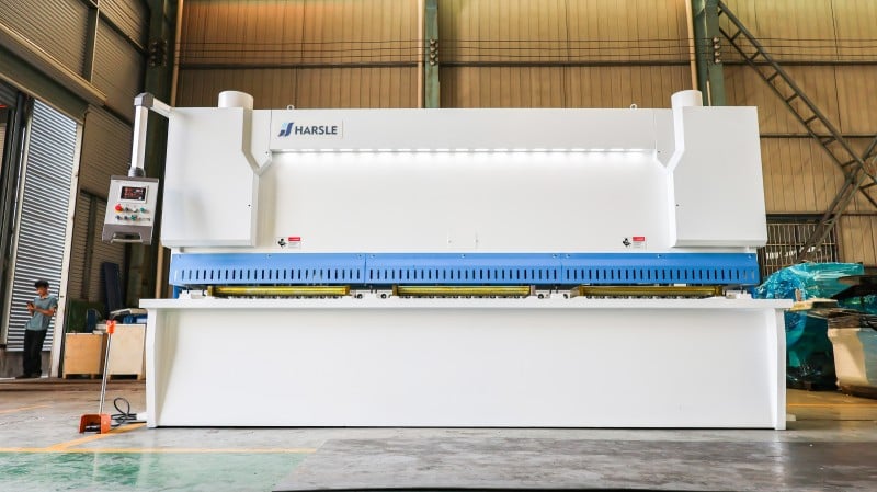
1.Hydraulic Shearing Machine Picture
2.Introduction
Cutting is the process of cutting a sheet into strips, or blocks before the production of the coil.

Schematic diagram of the cutting process
1—upper blade; 2—sheets; 3—lower blade
3. Sheet Material Is Sheared and Deformed by Shearing Machine Blades
● When the shearing is performed, the scissors are fixed, the upper scissors move downwards, and when the cutting starts, the upper scissors blade presses the sheet, and a pair of shearing force F and corresponding torque Fd force the sheared sheet to rotate, but will be subjected to the rotation process. The side of the scissors blocks the pair of side thrusts FT and the corresponding moment FTc in the other plane of the scissors.
The direction prevents the rotation of the sheet. When the shear starts, the sheet angle increases with the increase of the indentation depth. And the torque FTc also increases, so the cutting edge is pressed to a certain depth and there is Fd = FTc, then the sheared material will not rotate until it is sheared under the shear force.
● This type of equipment for shearing sheets is called a shearing machine.

4.Typical structure of the shearing machine
Ordinary shearing machine generally consists of the fuselage, transmission system, tool holder, presser, front block, rear block, feeding device, blade gap adjustment device, lighting line device, lubrication device, electrical control device, etc. The main components of which are structured as follows.

a)Guillotine shearing machine b) Forward tilting shearing machine c)、d)swing shearing machine
1—metal sheet 2—presser 3—upper blade 4—back gauge device 5—lower blade
5.Typical structure of the shearing machine – the fuselage
The fuselage is generally composed of left and right columns, work tables, beams and the like.
The fuselage is divided into a casting combination structure and an overall welded structure.
Casting assembly structure fuselage mostly uses castings, and the components are connected together by studs and pins.
The structure of this fuselage is heavy, the rigidity is poor, and the machining work of the joint surface is also large.
Compared with the casting structure, the overall welded structure has the advantages of lighter body quality, good rigidity and easy processing.
At present, the fuselage with integrated steel plate welded structure is increasing.
6.The Usage Point
⑴The thickness, material properties and shape of the shear sheet should be coordinated with the shearing method and shearing equipment, and it must not be violated.
⑵Before cutting, adjust the gap of the blade according to the thickness of the sheet and check if the cutting edge is sharp.
⑶Adjust the material blocking device according to the size of the shearing plate. After the test is passed, tighten the screws and check and adjust them in batch production.
⑷Before using the shearing machine, check the clutch, brakes and safety devices of the machine are normal.
⑸In the case of multi-person operation, it is necessary to coordinate and comply with the safe operating procedures.
Shearing Machine Working Principle
After shearing, the shearing machine should ensure the straightness and parallelism of the sheared surface of the sheared sheet, and minimize the distortion of the sheet to replace the workpiece. The upper blade of the shearing machine is fixed on the tool holder, and the lower blade is fixed on the work table. A support ball is mounted on the workbench so that the sheet is not scratched when it slides over it.
The back gauge is used for sheet positioning and the position is adjusted by the motor. The press cylinder is used to compress the sheet to prevent the sheet from moving during shearing. The guardrail is a safety device to prevent accidents. The return journey is generally based on nitrogen, which is fast and has a small impact.


Flat Blade Shear and Oblique Edge Shear
The flat blade is cut, and the sheet is in contact with the entire length of the upper and lower cutting edges. The shearing force is large, the power consumption is large, the vibration is large, but the cutting quality is good, straight and without distortion. Flat blade cutting is mostly used for small shearing machines and thin plate cutting, and there are many mechanical transmissions.
The oblique edge shear is progressive, the instantaneous shear size is smaller than the plate width, and the upper and lower cutting edges are shear angles (0.5-4°). Some hydraulic shearing machines are adjustable, which are related to shearing force and shear stroke. The quality is not as good as the flat blade shear, there is distortion, but the shear force is small, and it is used in large and medium shearing machines.
The shearing machine is divided into two types according to the movement mode of the tool holder: linear and oscillating. The linear blade is rectangular, four-sided, durable, and the cutting edge clearance must be adjusted.
Three-point rolling guide

The tool holder of the pendulum shearing machine swings around a point, the roughness of the section is small, the dimensional accuracy is high, the slit is perpendicular to the plane of the plate, and the tool holder is a box-type component:

Hydraulic schematic of Shearing Machine
Example model: QC11K-6*2500
●QC11K Hydraulic Shearing Machine:
The shearing machine is divided into a linear type and a swing type according to the movement mode of the tool holder. The linear structure is relatively simple (like a gate, so it is also called a gate type). It is easy to manufacture, the blade section is rectangular, and the four sides can be used as a blade, so it is more durable. The tool holder of the swing shearing machine oscillates around a fixed point during shearing. The advantage is that the friction and wear between the upper and lower cutting edges are small, the blade deformation is small, and the cutting precision is high.
| Model | Shearing Thickness (mm) | Shcaring Width (mm) | Stroke Times (cuts/min) | Back-gauge Rang (mm) | Shearing Angler(°) | Main Power (KW) | Overall Dimensions (L×W×H)(mm |
| 6×2500 | 6 | 2500 | 16~35 | 20~600 | 30’~1°30 | 7.5 | 3200×1500×2100 |
| 6×3200 | 6 | 3200 | 14~35 | 20~600 | 30’~1°30 | 7.5 | 3900×1580×2150 |
| 6×4000 | 6 | 4000 | 10~30 | 20~600 | 30’~1°30 | 7.5 | 4700×1650×2250 |
| 6×5000 | 6 | 5000 | 10~30 | 20~800 | 30’~1°30 | 11 | 5700×1800×2380 |
| 6×6000 | 6 | 6000 | 8~25 | 20~800 | 30’~1°30 | 11 | 6700×2000×2650 |
| 8×2500 | 8 | 2500 | 14~30 | 20~600 | 30’~2° | 11 | 3200×1550×2150 |
| 8×3200 | 8 | 320 | 12~30 | 20~600 | 30’~2° | 11 | 3950×1750×2350 |
| 8×4000 | 8 | 4000 | 10~25 | 20~600 | 30’~2° | 11 | 4700×1800×2480 |
| 8×5000 | 8 | 5000 | 10~25 | 20~800 | 30’~2° | 15 | 5700×1950×2600 |
| 8×6000 | 8 | 6000 | 8~20 | 20~800 | 30’~2° | 15 | 6700×1980×2650 |
| 12×2500 | 12 | 2500 | 12-25 | 20~800 | 30’~2° | 15 | 3250×1680×2250 |
| 12×3200 | 12 | 320 | 12~25 | 20~800 | 30’~2° | 15 | 3980×1800×2550 |
| 12×4000 | 12 | 4000 | 8~20 | 20~800 | 30’~2° | 15 | 4800×1950×2650 |
| 12×5000 | 12 | 5000 | 8~20 | 20~1000 | 30’~2° | 22 | 5800×2150×2700 |
| 12×6000 | 12 | 6000 | 6~20 | 20~1000 | 30’~2° | 30 | 6800×2450×2900 |
| 16×2500 | 16 | 2500 | 12~20 | 20-800 | 30’~1°30° | 22 | 3280×1830×2520 |
| 16×3200 | 16 | 3200 | 12~20 | 20~800 | 30’~1°30° | 22 | 3950×1950×2650 |
| 16×4000 | 16 | 4000 | 8~15 | 20~800 | 30’~1°30° | 22 | 4800×1970×2700 |
| 16×5000 | 16 | 5000 | 8~15 | 20~1000 | 30’~1°30° | 30 | 5800×2250×2870 |
| 16×600 | 16 | 6000 | 6~15 | 20~1000 | 30’~1°30° | 37 | 6800×2450×3150 |
| 20×2500 | 20 | 2500 | 10~20 | 20~800 | 30’~3° | 30 | 3400×2260×2520 |
| 20×3200 | 20 | 3200 | 10~20 | 20~800 | 30’~3° | 30 | 4100×2300×2700 |
| 20×4000 | 20 | 4000 | 8~15 | 20~800 | 30’~3° | 30 | 4900×2500×2880 |
| 20×5000 | 20 | 5000 | 8~15 | 20~1000 | 30’~3° | 37 | 5900×2750×2980 |
| 20×6000 | 20 | 6000 | 6~15 | 20~1000 | 30’~3° | 37 | 6900×2850×3200 |
| 25×2500 | 25 | 2500 | 8~15 | 20~800 | 30’~3° | 37 | 3420×2400×2650 |
| 25×3200 | 25 | 3200 | 8~15 | 20~800 | 30’~1°30° | 37 | 4150×2500×2750 |
| 25×4000 | 25 | 4000 | 6~12 | 20~100 | 30’~1°30° | 37 | 4900×2600×2950 |
| 30×2500 | 30 | 2500 | 8~12 | 20~1000 | 30’~1°30° | 55 | 3450×2600×2750 |
| 30×3200 | 30 | 3200 | 8~12 | 20~1000 | 30’~4° | 55 | 4150×2700×2850 |
| 30×4000 | 30 | 4000 | 8~12 | 20~1000 | 30’~4° | 55 | 4900×2900×3100 |
| 40×2500 | 40 | 2500 | 4~10 | 20~1000 | 30’~4° | 55 | 4000×2950×3150 |
| 40×3200 | 40 | 3200 | 4~10 | 20~1000 | 30’~4° | 55 | 4900×3050×3680 |
●Solenoid valve action table and technical requirements

skills requirement
● The maximum working pressure of the hydraulic system is 18Pa, and the pressure of the relief valve (4) is adjusted to 18MPa.
● The accumulator (17) is filled with nitrogen pressure of 3-5 MPa, and the ball valve (14, pressure gauge 16) has an oil pressure of 8-14 MPa (adjusted according to the tool return status).
● The normal working oil temperature range of the system is 10-60 degrees.
● The hydraulic system uses the working medium L-HM46 anti-wear hydraulic oil.
● Hydraulic system cleanliness requirements NAS11
●Hydraulic parts model

●Shearing machine hydraulic system

●Oil pump starting and oil filling
First, close the ball cylinder valve 11 and loosen the main relief valve 4 counterclockwise to start the oil pump motor, manual solenoid valve YV11 valve core, adjust the main relief valve 4 handwheel clockwise, and observe the main pressure gauge value, the pressure will be locked after being adjusted to the pressure specified by the system at 17 MPa. Then turn the “oil-filled” switch on the operation panel to the “on” position, the solenoid valves YV1, YV2, and YV4 are energized, the shearing machine is filled with oil, the tool holder descends to the lower end point, and the ball valve 14 is opened for oil filling.
During the process, observe that the pressure value in the accumulator pressure gauge 16 rises to 8 to 14 MPa (depending on the return speed of the tool holder), close the ball valve 14, and then turn the “oil-filled” switch to the “off” position. The lower pedal switch “up” upper bracket is raised to the top dead center position, the oil filling work is completed, the pressure cylinder ball valve 11 is opened, and the machine can enter normal operation.
●Stop
When the solenoid valve YV11 is de-energized, the hydraulic oil is from the oil pump → overflow valve → return to the fuel tank. At this point, the tool holder does not work.
7.Cutting
When the foot switch is “down”, the solenoid valve YV1 is energized, and the hydraulic oil is turned back to the tank through the solenoid valve; the oil pump is discharged through the valves 10, 12 into the upper chamber of the cylinder 18, and the oil in the lower chamber of the cylinder 18 enters the cylinder. In the upper chamber 19, the lower chamber of the cylinder 19 enters the accumulator 17 to form a series oil passage; the other oil enters the pressure cylinder 7 via the ball valve 11. At this time, the press cylinder moves downward to press the workpiece.
As the pressure increases, the tool holder body overcomes the support force of the lower chamber of the cylinder 19 and moves downward to the bottom dead center. The YV1 and YV2 power cut ends. The oil line working pressure is controlled by the relief valve 4, and the pressure value is read from the pressure gauge 9.
When stepping on the foot switch “up”, the oil pump oil is returned to the oil tank through the overflow valve 4, at this time YV3 is energized, the tool holder is returned under the action of the accumulator, and the pressure cylinder is under the action of the spring, wherein the oil passes through the valve 6. The valve 10 is returned to the fuel tank, and the tool holder is raised to the top dead center to complete the entire cutting process.
8.Maintenance
When cleaning the hydraulic system, to prevent oil injection! The accumulator lower ball valve 14 should first be opened and released to make the tool holder fall and then inspected. After the overhaul is completed, follow the above instructions for “Oil pump start and oil filling”.
9.Common faults and clearing of fault
● Oil pump noise
The oil pump has a large oil absorption resistance. Check the suction port, filter, and remove the blockage.
The oil level is low. Fill the tank with the oil window centerline.
The viscosity of the oil is large. Replace the hydraulic fluid.
The oil temperature is too low. Start the oil pump idling for a while to heat up or install the heater
● Cutting speed is too slow
The oil pump has insufficient oil. Inspection oil pump
Leakage in the system. Check pumps, valves, cylinders, etc., one by one
The pressure regulator is out of order. Service valve.
Insufficient pressure. Adjust the pressure to 18MPa.
● Cylinder overtravel motion
The trip is not working properly. Inspection block and travel switch
● Oil temperature is too high
The oil pump leaks too much. Repair the oil pump.
The pump return line is blocked or not smooth. Repair the return line.
The oil is dirty. Replace or improve the cleanliness of the oil.
● Insufficient cutting
The oil pump cannot establish pressure. Repair the oil pump.
System and valve leak or malfunction. Overhaul the valves and oil leaks.
Solenoid valve YVI cannot be turned off. Check for circuit signals or if the spool is stuck.
● The oil circuit cannot establish pressure, and the upper tool holder does not move.
Poor contact of solenoid valve electrical plug. Check the plug.
The solenoid valve spool is stuck or pulled. Remove the valve core grinding.
There is no debris in the valve plug seal. Cleaning.
The throttle hole in the valve is blocked. Disassemble the cleaning.
● Tool holder return is too slow
The solenoid valve is not commutating. Repair the solenoid valve.
The accumulator has insufficient nitrogen pressure. The nitrogen pressure is 3~5MPa.
The upper tool holder and the press cylinder are not coordinated. Check if the solenoid valve of the press cylinder is working properly.
● The tool holder slowly descends when jogging
Poor sealing of the reversing valve cone. After removing the reversing valve, pour kerosene from one side to check for leaks; if it leaks, replace or grind the sealing surface.
The upper and lower chambers of the cylinder are oiled. Check that the plunger seal is good.
● The two cylinders are not synchronized when the upper tool holder returns
The internal piston seal of the cylinder is poorly connected to the upper and lower sides of the oil. Replace the plunger seal.
● Hydraulic system maintenance ideas
The failure of the hydraulic system must be based on the principle of easy and difficult, first and second, internal and internal electrical control after hydraulic control.
Review the hydraulic schematic and understand the logical relationship of the action. Do not blindly start.
The relationship between pressure and flow is the pressure generated by the flow to analyze the cause of the failure.
Ask the operator to find out the equipment health and the anomalies that occurred when the fault occurred.


