


Sheet Metal Bending Stamping And forming Process Guide

The process of bending a blank into a certain angle or a certain shape with mechanical equipment and tools is called mechanical bending. According to the different types of bending equipment and processed materials, mechanical bending can be divided into sheet metal bending and stamping, sheet metal rolling, sheet metal bending, and so on. In the bending process, according to whether the blank is heated, the bending process can be divided into cold bending and hot bending.
Sheet metal stamping and bending involve using presses and specialized or general dies to apply a bending force, causing the blank to undergo plastic deformation. The bending process is completed within the die’s cavity. This method plays a key role in mechanical bending and is one of the primary techniques for shaping sheet metal. It allows the forming of complex curved parts with high dimensional precision, making it essential for producing components with intricate geometries.
Sheet Metal Bending Process
The following figure shows the bending deformation of the sheet metal. For the convenience of observation, before bending, mark the bending start line, bending middle line, and bending end line on the bending part of the sheet metal. The following figure (a) and the following figure (b) are bending Parts after forming.
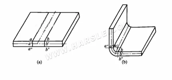
As shown in Figure (a), the three lines ab = a’b’ = a”b” are equal before bending. After bending, the inner layer shortens and the outer layer stretches, resulting in ab < a’b’ < a”b”, as seen in Figure (b). This indicates that during bending, the inner layer is compressed while the outer layer is under tension. Between them lies a layer whose length remains unchanged—this is the neutral layer. Since its length stays constant, it serves as the reference for calculating the flat length of the material. Its position depends on the bending radius and is typically approximated at half the material thickness.
After the sheet is bent, the thickness in the bending zone generally becomes thinner, and cold work hardening occurs, so the rigidity increases and the material in the bending zone appears hard and brittle. Therefore, if the bend is repeated or the rounded corner is too small, it will easily break due to tension, compression, and cold work hardening. Therefore, when bending, the number of bending and corner radius should be limited.
On the other hand, the bending of the sheet is the same as other deformation methods. When bending, the outer surface of the sheet is stretched and the inner surface is compressed. While plastic deformation occurs, there is also elastic deformation. Therefore, when the external force is removed, the bending Produce angle and radius rebound. The angle of rebound is called the rebound angle.
Minimum Bending Radius And Bending Spring Back
Controlling or reducing the spring back of the bending angle and the bending radius of the bending part is an important content for obtaining the accuracy of the bending part and ensuring the quality of the bending part. In production processing, the control of bending angle and bending radius spring back is usually achieved by the minimum bending radius and bending spring back value.
⒈Minimum bending radius The minimum bending radius generally refers to the minimum value of the inner radius of the part that can be obtained by the press bending method. When bending, the minimum bending is limited by the maximum allowable tensile deformation of the outer layer of the sheet. If the deformation exceeds this degree, the sheet will crack.
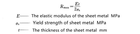
During the bending process, the bending radius is too small to cause bending cracks, but the bending radius is too large, the sheet will be completely restored to the original straight state due to spring back, at this time, the bending radius cannot be greater than the maximum bending radius Rmax:
⒉The determination of the bending spring back value is generally determined according to the relative bending radius r/t (r is the inner fillet radius of the bending part, t is the thickness of the blank).
●When rlt<(5~8), the rebound value of the bending radius is not large, so only the angle rebound is considered.
●When r/t≥10, due to the relatively large bending radius, not only the angle of the workpiece rebounds, but the bending radius also has a larger rebound.
Process Requirements For Stamping And Bending
The stamping and bending process can complete the processing of more complex shape parts, and the produced parts have the advantages of higher precision and good product consistency. To improve the bending quality and simplify the mold manufacturing, there are specific requirements in the following aspects for the processed bending parts.
⒈The fillet radius of the bent part should not be too large or too small. If the fillet radius is too large, it is not easy to guarantee the bending angle and fillet radius of the part due to the influence of spring back. If the fillet radius is too small, because it is easy to bend and crack, it needs to be bent twice or more, that is, bend into a corner with a larger fillet radius in advance, and then bend to the required bending radius, thereby prolonging the production cycle. It also brings disadvantages to bending work.
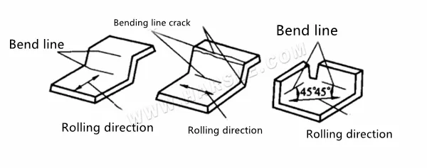
⒉When the relative bending radius r/t<0.5~1, the bending line should be perpendicular to the direction of the rolled fiber of the material. If the parts have different bending directions, the angle between the bending line and the direction of the rolled fiber should be maintained at 45°.
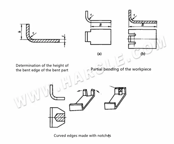
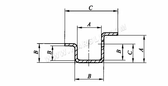
⒊The bending height of the bending part should not be too small, and its value is h>r+2t (see the figure below). Otherwise, because the supporting surface of the flange is not enough on the mold, it is not easy to form a sufficient bending moment, and it is difficult to obtain a part with an accurate shape. If the height of the flange does not meet the above-specified range, generally technical measures should be taken, that is, first lengthen the flange, and then cut off the excess part after bending.
⒋For parts with a curved stepped shape, because they are easy to tear at the root of the rounded corners, the length B of the unbent part should be reduced to make it exit outside the bending line. If the length of the part is not allowed to be reduced, a groove must be cut between the bent part and the unbent part, as shown in the figure.
⒌For parts with notches on the curved edges, the notches should not be made in advance, and they will be cut off after they are formed. In this way, it can avoid the phenomenon of forks or forming difficulties during the bending process.
⒍When the sheet with holes is bent, the distance I from the edge of the hole to the center of the bending radius should be ensured: when t<2mm; l≥t, when t≥2mm, l≥2t. If the hole is located in the bending deformation zone, the shape of the hole will be distorted.
⒎The shape and size of the bent parts should be as symmetrical as possible. To ensure that the material is balanced during bending and prevent slippage, the bending parts should be r=r2, r3=r4.
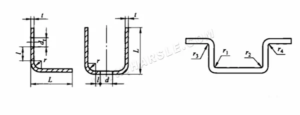
Symmetrical bending parts
⒏The section of the blank obtained by shearing or punching often has burrs, so it is easy to cause stress concentration during bending. Therefore, the burr should be filed before bending, and at the same time, the side of the burr should be close to the punch in the compression zone and then bend to prevent cracks on the outer edge of the part.
Types And Structure of Bending Die

There are many types of bending dies. According to the different shapes of the processed bending parts, the bending dies can be divided into V-shaped bending dies, U-shaped bending dies, and several-shaped bending dies. According to whether the mold uses a pressing device and its working characteristics, the bending dies can be divided into open type, with pressing device type, pendulum type, pendulum shaft type, etc. The common types and structures of bending molds are as follows.
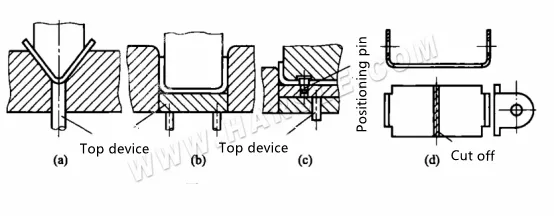
⒈V. U-shaped part open bending molds that complete a bending process in one punching stroke of the press are called single-process bending molds. The open bending die structure can complete the processing of simple bending parts with low requirements for bending shape and dimensional accuracy. The figure below shows the open bending die structure of V and U-shaped parts, which is the simplest form of die structure.
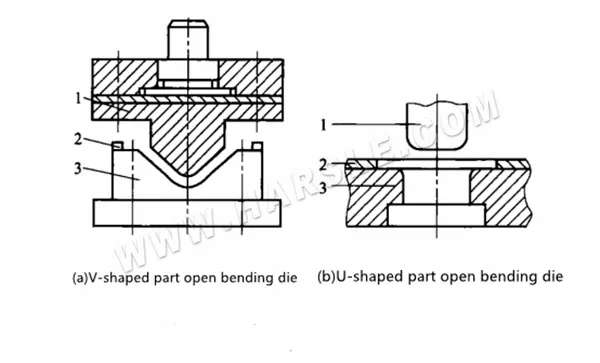
The upper and lower molds of the whole set of molds are open-type, convenient to manufacture, and have strong versatility. However, when the mold is used for bending, the sheet material is easy to slide, the side length of the bending part is not easy to control, and the bending accuracy of the workpiece is not easy. The bottom of the U-shaped piece is high and uneven.
⒉To improve the bending accuracy of the bent parts and prevent the sliding of the bent blank, the bending die structure with the pressing device can be used as shown in the
figure.
In Figure (a), the spring ejector rod 3 functions as a pressing device to prevent the blank from shifting during bending. In Figure (b), the blank is clamped between punch 1 and pressing plate 3. As they descend, the unpressed ends of the material bend along the female die’s rounded corners, entering the gap between the punch and die to form a U-shape. Throughout the bending process, constant pressure from the punch and pressing plate helps maintain the flatness of the U-shaped part’s bottom and improves overall bending precision.

⒊The semicircular bending mold diagram shows the structure of the semicircular bending mold. When working, put the blank between the positioning plates so that it cannot move freely. When the press is down, the punch will drop to a certain position to contact the surface of the material. When the punch continues to drop, the blank begins to bend, and the fillet rg slides. At the same time, the ejector 8 moves downward and compresses the spring. As the punch advances, the blank is bent and formed, and the spring is compressed to store energy. When the punch rises, the ejector pin uses the elastic force of the spring to hold the part Eject.

To ensure the balance of the force when the blank is bent, the fillet radius r on both sides of the die 5 should be equal. The die is fixed on the lower die base 7 with two positioning pins and four screws. The die has two U-shaped positioning plates 4.
Figure 7-35 illustrates various dumpling chain bending molds. In (a), the pre-bending mold forms a curved arc from a straight blank end before final rounding. Figure (b) shows a vertical dumpling chain bending mold, which has a simple structure and is easy to manufacture—suitable for bending thicker, short-length parts with low precision needs. Figure (c) presents a horizontal bending mold, where the inclined wedge 3 drives concave die 4 to bend the part horizontally. The convex die 1 also presses the material. Though it offers better forming quality, the structure is more complex. For high-precision forming, a mandrel should be used.

Generally speaking, when r/t>0.5 (r is the radius of the coil) and the quality of the coil is high, two pre-bending procedures should be used, and then the coil; when r/t=0.5~2.2, but the coil When the round quality requirements are general, the round can be rolled with one pre-bending; when rlt ≥ 4 or there are more stringent requirements on the round, the round with a mandrel should be used.
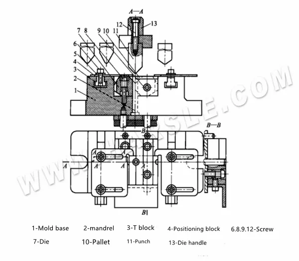
⒌Bending molds for closed and semi-closed bending parts The bending molds for closed and semi-closed bending parts are more complicated, and pendulum blocks and inclined wedge structures are mostly used in bending molds. Figure (b) is a one-time directly bent into the pendulum block type bending die structure of the clamp type cylindrical part shown in Figure (a), because the bending process is completed by the swing of the movable die 12 around the mandrel 11, so It is called swing bending die. The pendulum block bending mold structure can complete the processing of bending semi-closed and closed bending parts.
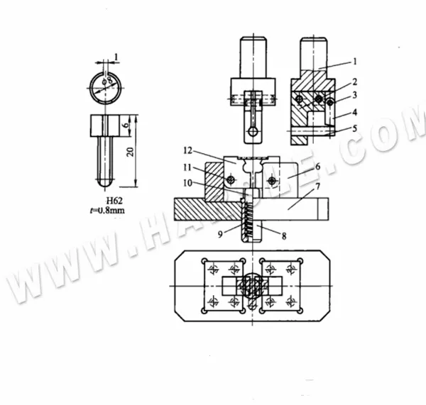
One-time direct bending into the pendulum bending dies structure of the clamp type cylindrical part as shown in Figure (a). Since the bending process is completed by the swing of the movable die 12 around the mandrel 11, it is called swing bending mold. The pendulum block bending mold structure can complete the processing of bending semi-closed and closed bending parts.
When the mold is working, the blank is positioned by the positioning groove on the movable die 12. When the upper mold moves downward, core 5 first bends the blank into a U shape, and then core 5 presses the movable die 12 to swing it toward the center to bend the workpiece. After the upper mold rises, the movable concave mold 12 is lifted and separated by the top post 10 under the action of spring 9. The workpiece remains on core 5 and is taken out longitudinally.
The following figure shows the structure of the bending die with an oblique wedge for closed and semi-closed bending parts with a bending angle of less than 90°.
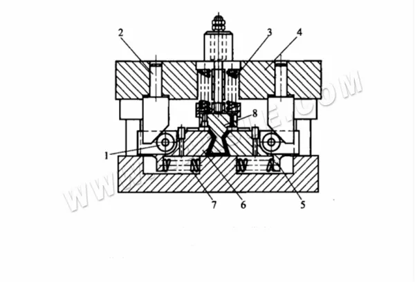
During operation, the blank is first pressed into a U-shape by punch 8. As the upper template 4 continues to move downward, spring 3 compresses, and the two inclined wedges 2 mounted on the template push against rollers 1. This drives the movable concave modules 5 and 6 inward, bending both sides of the U-shaped part to an angle less than 90°. When the upper mold returns, spring 7 resets the modules. Since the forming relies on the elastic force of spring 3, the mold is suitable only for bending thin materials due to its limited pressing force.
Determination of The Main Process Parameters of Bending
To ensure the quality of bending parts, the following process parameters should be determined when formulating the bending process and the design of related bending dies.
⒈Calculation of bending force: The bending force refers to the pressure applied by the press when the workpiece completes the predetermined bending. The bending force includes free bending force and correcting bending force.
●Calculation of free bending force: The bending force F during free bending refers to the bending force required for bending deformation of the sheet metal.
Where F free bending force-free bending force at the end of the stamping stroke, N;
K——safety factor, generally take K=1.3;
b——the width of the bent part, mm;
t——the thickness of the bending material, mm;
r——the inner bending half of the bending part, mm;
The strength limit of the material, MPa.
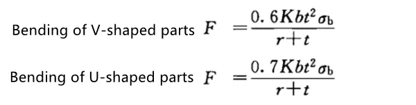
●Calculation of correcting bending force: Since the correcting bending force is much larger than the pressing bending force when correcting bending, and the two forces act one after another, only the correcting force needs to be calculated. The correction force F of V-shaped parts and U-shaped parts is calculated by the following formula F correction bending force = Ap
Where F——the bending force when correcting the bending, N;
A——The vertical projection area of the correction part, mm2;
p——correction force per unit area, MPa, select according to the table.
| Material | Thickness t/mm | |
| ≤3 | >3~10 | |
| Al | 30~40 | 50~60 |
| Brass | 60~80 | 80~100 |
| 10~20 Steel | 80~100 | 100~120 |
| 25~35 Steel | 100~120 | 120~150 |
| Titanium alloy TA2 | 160~180 | 180~210 |
| Titanium alloy TA3 | 160~200 | 200~260 |
●Calculation of ejector force or discharge force: When the bending die is equipped with an ejector device or discharge device, the ejector force F or discharge force F can be approximately 30% of the free bending force~ 80%.
●Determination of the tonnage of the press: the tonnage of the press is determined separately according to the two conditions of free bending and correcting bending.
When free bending, considering the influence of the ejector force or unloading force during the bending process, the tonnage F of the press is F press tonnage ≥ (1.3~1.8) F free bending force.
When correcting the bending, the correcting force is much larger than the ejector force and the unloading force. The weight of F top or F unloading is insignificant, so the tonnage of the press is F press tonnage ≥ F correcting bending force.
⒉Determination of the Bending Die Gap The size of the gap Z between the punch and the die has a great influence on the pressure required for bending and the quality of the parts.
When bending a V-shaped workpiece, the gap between the convex and concave molds is controlled by adjusting the closing height of the press, so there is no need to determine the gap on the mold structure.
When bending U-shaped workpieces, an appropriate gap must be selected. The size of the gap has a great relationship with the quality of the workpiece and the bending force. For general bending parts, the gap can be obtained from the table or directly obtained by the following approximate calculation formula.
When bending non-ferrous metals (red copper, brass), Z=(1~1.1)t
When bending steel=(1.05~~1.15)t
When the precision of the workpiece is high, the gap value should be appropriately reduced, taking Z=t. In production, when the material thickness is not required to be thinner, to reduce springback, etc., also take the negative gap, take Z=(0.85 ~0.95)t.
⒊Calculating the size of the working part of the bending die The design of the working part of the bending die is mainly to determine the convex and concave mold fillet radius and the size and manufacturing tolerance of the convex and concave molds.
The corner radius of the punch is generally slightly smaller than the radius of the inner corner of the curved part. The corner radius at the entrance of the die should not be too small, otherwise, the surface of the material will be scratched. The depth of the die should be appropriate. If it is too small, there will be too many free parts at both ends of the workpiece, and the bent part will rebound greatly, and it will not be straight, which will affect the quality of the part; if it is too large, it will consume more die steel and require a longer press stroke.
The size of the die thickness H and groove depth his determined for the bending of V-shaped parts. The structure of the die is shown in the figure. The size of the die thickness H and groove depth his determined in the table.
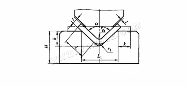
The determination of the dimensions H and h of the curved V-shaped part.
| Thickness | <1 | 1~2 | 2~3 | 3~4 | 4~5 | 5~6 | 6~7 | 7~8 |
| h | 3.5 | 7 | 11 | 14.5 | 18 | 21.5 | 25 | 28.5 |
| H | 20 | 30 | 40 | 45 | 55 | 65 | 70 | 80 |
Note:
1. When the bending angle is 85°~95°, L1=8t, r convex=r1=t.
2. When k (little end) ≥ 2t, the value of his calculated according to the formula h=L1/2-0.4t.
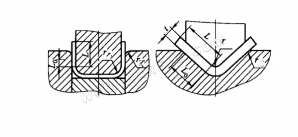
●The determination of the radius and depth of the bend fillet The determination of the fillet radius r concave and the depth L0 of the V-shaped and U-shaped bends are shown in the figure and the table below.
●Calculation of working size of bending punch and die.
When the workpiece needs to ensure the external dimensions, take the concave mold as the reference, and the gap is taken on the punch; if the workpiece is marked with the internal dimensions, take the punch as the reference, and the gap is taken on the concave mold.
When the workpiece needs to ensure the external dimensions, the size of the concave mold L and the size of the punch L convex are calculated according to the following formulas:
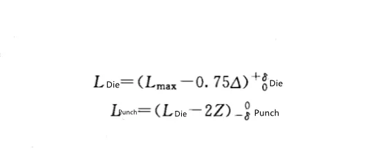
When the inner dimension of the workpiece is to be guaranteed, the punch size L convex and the concave die size L concave are calculated according to the following formulas:

Essentials of Bending Die Design and Application
The use of bending molds can complete the processing of various relatively complex shapes. Among them, the design of the bending mold is the key to ensuring the shape, size, and accuracy of the bending parts. For this reason, the following essentials must be paid attention to when designing and applying the bending mold.
⒈To produce qualified bending parts economically and reasonably, it is usually required that the dimensional tolerance level of the bending part should be better than IT13, and the angle tolerance should be greater than 15′. The following table shows the tolerance levels that can be achieved for various dimensions of stamping and bending parts.
The angle tolerances of general bending parts are shown in the table. The precision-level angle tolerances in the table can only be achieved by adding shaping procedures.
| Thickness t/mm | A | B | C | A | B | C |
| Economical | Precision | |||||
| ≤1 | IT13 | IT15 | IT16 | IT11 | IT13 | IT13 |
| >1~4 | IT14 | IT16 | IT17 | IT12 | IT13~14 | IT13~14 |
Tolerance class of bent parts
| Short side of bending part | >1~6 | >6~10 | >10~25 | >25~63 | >63~160 | >160~400 |
| Economical | ±1°30‘~±3° | ±1°30‘~±3° | ±50‘~±2° | ±50‘~±2° | ±25‘~±1° | ±15‘~±30’ |
| Precision | ±1° | ±1° | ±30‘ | ±30‘ | ±20‘ | ±10‘ |
⒉A proper bending process plan is essential to ensure the accuracy and quality of formed parts. For simple shapes, one-step bending is often sufficient, focusing on shape and dimensional precision. Complex curves typically require multiple bending stages. Small parts are best formed using complex dies for safety and accuracy. Progressive dies are suitable for strip or coil materials. When bending multiple angles, start with the ends before shaping the center, ensuring each bend supports the next. For asymmetrical or highly bent parts, stability and accuracy are critical. Hole or notch punching should be done after bending to reduce deformation risks.
⒊When designing a bending die, it’s essential to consider the forming process of the bent parts, analyze potential structural issues during bending, and apply targeted solutions in the die design. This ensures the mold meets processing requirements. For example, in single-angle bending, unbalanced bending forces can cause the sheet to slip. To prevent this, anti-slip measures should be included in the die. As shown: Figure (a) uses existing or added holes for positioning; Figure (b) applies a positioning block and strong edge pressure to prevent side movement; Figure (c) combines strong pressing force with wedge bending for better accuracy and reduced springback.
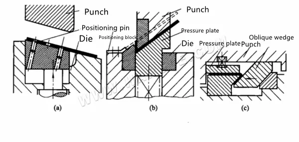
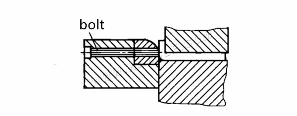
The anti-slip design of the bending die applies to all single-angle bends. To enhance the sheet-holding effect of the press plate, besides increasing spring force, additional methods can be used if surface finish is not critical. In Figure (a), a sharp pin is embedded in the lower die’s discharge block, protruding 0.1–0.25 mm at a 60° angle to grip the sheet when pressed. The pin height is adjustable with a threaded bolt and locking nut. Figure (b) shows a similar sharp pin on the upper mold’s spring plate, which embeds into the sheet during pressing to prevent slippage.

Ways to increase the pressing force
The commonly used press pin form is shown in the figure:
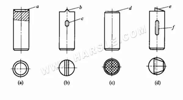
Common form of pressing pin
Figure (a) shows a method where a sharp edge is wedged into the sheet surface, with a depth of less than 0.12 mm to enhance grip. Figure (b) illustrates a stop pin with a blade (b) for improved effectiveness; to prevent the round pin from rotating, an additional pin is fitted into a long groove (c). Figure (c) uses a pin with an embossed head, suitable for cases where the sheet doesn’t move significantly. It leaves no visible marks on the surface after use. Figure (d) is designed for applications with significant sheet movement. It features a sharp wedge (e) angled at 8°–12°, a relief angle of 25°–30°, and includes a long groove (f) to prevent bolt rotation.
When bending asymmetrical polygonal parts, using the die setup shown in Figure (a) can lead to defects. As the punch descends, point B first contacts the material, causing uneven force distribution and shifting the blank. When point C then makes contact, the material experiences bidirectional pressure. As the punch continues downward, friction at points A and C increases tension at point B, often resulting in tearing or deformation—compromising dimensional accuracy.
In contrast, using the inclined die structure shown in Figure (b) helps avoid these issues. Here, the working surfaces of both punch and die are angled so that point B lies on the vertical centerline, and the pressure center D evenly divides segment AC (i.e., AD = DC). This ensures balanced forces at points A and C during forming, preventing blank displacement and excessive stretching at point B. As a result, part accuracy and forming quality are significantly improved.

Bending method of asymmetric polygonal bending parts
⒋It is necessary to carefully analyze the processing material and surface quality requirements of the bending parts. For non-ferrous metals with high surface quality requirements and vulnerable to damage, to ensure the quality of the parts and the service life of the mold, the appropriate processing method should be determined and the corresponding mold structure should be designed. Generally, the available mold structure is as follows.
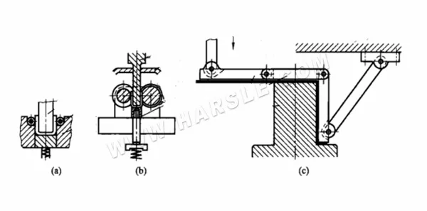
The following figure (a) is the mold structure with rollers added to the concave mold to reduce friction and protect the curved surface; the following figure (b) is the mold structure with only rollers; the following figure (c).
Bending die structure to protect the curved surface
It is a bending die with a lever. Because friction is eliminated, it helps to protect the curved surface. It can be used for bending workpieces with or without flanges.
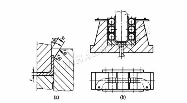
When bending thick or high-strength plates, an oblique-angle bending die, as shown in Figure (a), is recommended. The concave die opening is tilted about 30°, with a die-punch gap of 3t. The inner radius transitions smoothly between a rounded corner and a flat surface, where rd = (0.5–2)t and rd₂ = (2–4)t. If needed, the transition zone can adopt geometric forms like a parabola to facilitate smoother material flow, reduce resistance, and lower cavity stress. This design minimizes material buildup at the die corners, reduces strain on the workpiece, and enhances both forming quality and die longevity.
For bending thick non-ferrous metals, to avoid scratches or groove wear at the die edge and prevent plate deflection, roller dies—shown in Figure (b)—can be used. During operation, the blank is positioned between pins, and the punch bends it smoothly into place between the rollers. The die cavity depth is (8–12)t, and a slight negative gap of (0.9–0.95)t helps reduce springback by applying greater forming pressure.
Bending die for protecting thick plate bending
For metal bending, to prevent the workpiece and the die mouth from grinding out grooves during bending, and cause the deflection of the sheet material, the roller dies shown in Figure (b) can be used for bending. When working, after the workpiece blank is positioned between the positioning pins, the punch moves down, and the blank is smoothly bent to the bottom block between the rollers. The depth of the concave mold is ((8~12)t and the negative gap (0.9~0.95)t can be used. Large impact method to reduce rebound.
Besides, for the bending processing of non-ferrous metals, the round corners of the die should be kept smooth and clean at all times, and heat-treated to 58-62HRC. For bending processing of stainless steel, the working part of the die is best designed as an insert structure and made of aluminum bronze.
Bending of non-ferrous metals
⒌For V-shaped, U-shaped, Z-shaped, and other bent parts with simple shapes, multiple varieties, and small production batches that appear in production, to shorten the mold manufacturing cycle and reduce product manufacturing costs, general bending molds can generally be used to complete the processing of the parts.
⒍The general bending die structure for bending V and U-shaped parts is used on the press. The characteristic of this kind of mold is that the two concave molds 7 can be matched to make four angles, and they can be matched with four kinds of convex molds with different angles to bend V and U-shaped parts with different angles.
When working, the blank is positioned by the positioning plate 4, and the positioning plate can be adjusted back and forth and left and right according to the size of the blank. The concave mold 7 is installed in the mold base 1 and fastened by screws 8. The concave mold and the template are processed into an H7/m6 transitional fit, to ensure the bending quality and accuracy of the workpiece. After the workpiece is bent, it can be ejected by the ejector rod ⒉ through the buffer to prevent the bottom surface of the workpiece from bending.
The figure below shows the general bending die structure for bending U-shaped parts.
The working components of this mold set feature a movable structure, allowing flexibility in processing parts of varying widths, thicknesses, and shapes (such as U-shapes or channel forms). A pair of adjustable concave dies (14) are mounted inside the mold sleeve (12), and their working width can be set as needed using adjustment bolts (8) to match the width of different workpieces. Ejector blocks (13), kept in constant contact with the dies by springs (11), provide pressing and ejection functions via backing plates (10) and ejector rods (9). The main punches (3) are installed in a dedicated mold holder (1), with their width adjustable through bolts (2).
When bending parts, a secondary punch 7 is also needed, and the height of the secondary punch can be adjusted by bolts 4, 6, and inclined top block 5. When bending the U-shaped piece, it can be adjusted to the highest position.
Installation And Adjustment of Bending Die
Bending processing on the press with a bending die is the most important form of bending processing. The processing should be carried out in strict accordance with the stamping operation rules to prevent misoperation. To complete the bending process of the parts, the installation and adjustment of the bending die should be done first.
⒈The installation method of the bending dies The installation method of the bending die is divided into two types: the non-guided bending die and the guided bending die. The installation method is the same as that of the punching die. The installation of the bending die is the same as the gap between the convex and concave dies. In addition to the adjustment of the adjustment, discharge device, etc., the two bending dies should also complete the adjustment of the upper and lower positions of the upper bending die on the press at the same time. Generally, it can be carried out according to the following methods.

Universal bending die suitable for U-shaped and square-shaped parts
First, when installing the upper bending die, make a rough adjustment of the press slider position. Then, insert a gasket or sample slightly thicker than the blank between the lower face of the upper punch and the lower die’s discharge plate. Adjust the connecting rod length and manually rotate the flywheel or use jog mode repeatedly until the slider can smoothly reach bottom dead center without jamming. After confirming smooth operation, rotate the flywheel several times to verify consistency, then fix the lower die for a trial run. Remove the gasket before trial punching. If the result is satisfactory, re-tighten all fasteners and recheck before starting full production.
⒉The adjustment points of the bending die When the bending die is used for processing, to ensure the quality of the bending part, the bending die must be carefully adjusted. The adjustment and precautions mainly include the following aspects.
●Adjusting the gap between the punch (convex mold) and die (concave mold) is crucial for accurate bending. Generally, once the upper die is properly installed on the press, the vertical gap between the upper and lower dies is automatically set. The guiding components of the press ensure the correct relative position, maintaining consistent lateral clearance. However, for bending dies without guiding devices, lateral clearance must be manually adjusted using cardboard shims or standard test pieces. Only after confirming the proper gap should the lower die plate be fixed and trial bending performed.
●Adjustment of the positioning device. The positioning shape of the positioning parts of the bending die should be consistent with the blank. During the adjustment, the reliability and stability of its positioning should be fully guaranteed. Using the bending die of the positioning block and positioning nail, if the position and positioning are found to be inaccurate after trial punching, the positioning position should be adjusted in time or the positioning parts should be replaced.
●Adjustment of unloading and returning devices. The discharge system of the bending die should be large enough, and the spring or rubber used for the discharge should have sufficient elasticity; the ejector and the discharge system should be adjusted to be flexible in action, and the product parts can be discharged smoothly, and there should be no jams and Astringent phenomenon. The force of the unloading system on the product should be adjusted and balanced to ensure that the surface of the product after unloading is smooth and will not cause deformation and warpage.
⒊Precautions for adjusting the bending die When adjusting the bending die, if the position of the upper die is lowered, or you forget to clean out the gasket and other debris from the die, the upper die, and the lower die will be under the stroke during the stamping process. Violent impact at the dead center position may damage the mold or punch in severe cases. Therefore, if there are ready-made bent parts at the production site, the test piece can be directly placed on the working position of the mold for mold installation and adjustment, to avoid accidents.
Methods to Improve The Quality of Press-bent Parts
The main factors affecting the quality of press-bent parts are spring back, offset, fracturing, and changes in the cross-section of the deformed area. The measures and methods adopted mainly include the following aspects.
⒈Factors influencing the rebound value and prevention methods The forming process of the bent part goes through two stages from the elastic deformation of the material to the plastic deformation. Therefore, after the plastic deformation of the metal, elastic deformation is inevitable, resulting in bending spring back and tending to bend The direction of the front, so that the angle and fillet radius of the part after bending, the bending angle and fillet radius of the part and the die have a certain difference, that is, the bending spring back. According to the factors caused by bending spring back, the following measures can be taken.
●Take measures from the selection of materials. The rebound angle of the bending rebound is proportional to the yield limit of the material and inversely proportional to the elastic modulus E. Therefore, on the premise of meeting the requirements of the use of the bending parts, materials with a large elastic modulus E and a small yield strength os should be selected as much as possible to reduce the spring back during bending. Besides, according to experiments, when the relative bending radius r/t is 1 to 1.5, the rebound angle is the smallest.
●Improve the structural design of bending parts. Under the premise of not affecting the use of the bending parts, some structures can be improved in the design of the bending parts, and the rigidity of the bending parts can be enhanced to reduce the spring back. For example, reinforcing ribs can be set in the bending deformation zone, as shown in Figures (a) and (b). ), or adopt a U-shaped side wing structure, as shown in Figure (c), by increasing the section moment of inertia of the bending part, reducing the bending spring back.
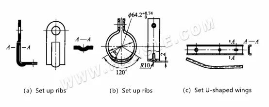
Bending structure to reduce springback
●Rebound compensation. For materials with the large elastic rebound, the punch and the top plate can be made to compensate for the rebound of the convex and concave surfaces, so that the bottom of the bent part will bend. When the bent part is taken out of the concave mold, the curved part will rebound and stretch. Straight, so that both sides produce inward deformation, thereby compensating for the outward rebound of the rounded corners, as shown in the figure.

Springback compensation
For harder materials, the shape and size of the working part of the mold can be corrected according to the rebound value.
●Take corrective bending instead of free bending or add corrective procedures. The following figure shows the mold structure where the corners of the bending punch are made into a partially protruding shape to correct the bending deformation zone. The principle of controlling the bending resilience is: when the bending deformation is over, the punch force will be concentrated on the bending deformation zone, forcing the inner metal to be squeezed to produce elongation deformation, and the bending resilience will be reduced after unloading. It is generally believed that a better effect can be obtained when the corrective compression of the metal in the bending deformation zone is 2% to 5% of the plate thickness.

Correction method of mold structure
⒉The main causes of deviation in bent parts include improper blank positioning in the die or unstable placement, which causes the applied force to become uneven and generate a horizontal component. Another reason is uneven friction during bending—especially with asymmetrical parts—where the blank tends to shift toward the side with greater resistance, pulling the opposite side into the die. Factors like die fillet radius, mold clearance, and slippage conditions significantly affect the deviation amount. To prevent bending deviation, measures such as improving blank positioning accuracy, optimizing die structure, and adjusting friction conditions should be implemented.
●Press the sheet tightly. The blanking device is used to gradually bend and shape the blank in a compacted state, to prevent the blank from sliding and obtain a flat workpiece, as shown in Figures (a) and (b).
●Choose a reliable positioning form. Use the hole on the blank or design process hole, insert the positioning pin into the hole and then bend it so that the blank cannot move, as shown in Figure (c).
●Make the billet force uniformly and symmetrically. When bending asymmetrically shaped parts, it is often encountered that the blanks move due to uneven forces. To ensure uniform force on the part during bending, the asymmetric shape can be combined into an asymmetrical shape, which is then cut after bending, as shown in Figure (d).
⒊Limit the bending radius to prevent bending cracks. Because the outer fiber of the bending part is stretched, the deformation is the largest. When the limit deformation value of the material is exceeded, it is easy to bend and crack. However, the tensile deformation of the outer fiber of the part is mainly determined by the critical bending radius that causes the material to crack. The minimum bending radius is related to factors such as the mechanical properties of the material, heat treatment state, surface quality, the size of the bending angle, and the direction of the bending line. According to the factors that cause bending cracks, the main measures that can be taken are as follows.
●Choose materials with good surface quality and no defects as the blank. Defective blanks should be cleaned up before bending. To prevent bending cracks, large burrs on the sheet should be removed, and small burrs should be placed on the inner side of the curved fillet.
●Take measures from the craft. For relatively brittle materials, thick materials, and cold-work hardened materials, heating, and bending are used, or annealing is used to increase the plasticity of the material before bending.
●Control the value of the inner bending angle. Under normal circumstances, the bending inner angle of bending should not be less than the minimum allowable bending radius in the design, otherwise, the deformation of the outer layer of metal during bending may easily exceed the deformation limit and break. If the bending radius of the workpiece is less than the allowable value, it should be bent two or more times, that is, first bend into a larger fillet radius, after intermediate annealing, then bend to the required bending radius by the correction process, so that it can Enlarge the deformation area and reduce the elongation of the outer layer material.
●Control the bending direction. When bending processing and parts layout, the bending line and the rolling direction of the sheet metal are specified in the following process. For unidirectional V-shaped bending, the bending line should be perpendicular to the rolling direction. For bidirectional bending, the bending line should preferably be at 45° to the rolling direction, as shown in the figure.
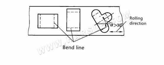
Control of bending direction
●To improve the manufacturability of a product’s structure, it’s essential to choose an appropriate fillet radius. For small bend radii and thick materials, process incisions or grooves can be added at local bend areas to prevent stress concentration outside the bending zone. Sharp corners, notches, or other geometric features that may lead to cracking or root breakage should be avoided. As shown in Figure (a), adding a slot on the inner corner of a part with a small bend radius helps prevent cracking. It’s recommended to move the sharp angle outside the bending zone by a distance b≥rfor safe forming.
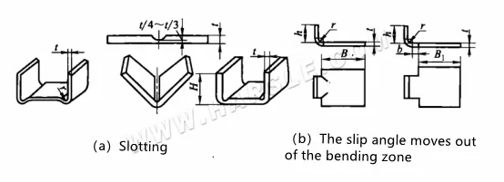
Improve the manufacturability of product structure
●When using a hot bending process, it’s important to avoid the blue brittle zone and the hot brittle zone. These temperature ranges reduce metal plasticity and increase deformation resistance, leading to brittle fractures. For example, carbon steel heated between 200–400 °C experiences aging effects that lower plasticity and raise resistance—this is known as the blue brittle zone, where fractures are brittle and appear blue. Similarly, in the 800–950 °C range, plasticity drops again, making the material prone to fracture during bending. Therefore, hot bending should avoid these critical temperature zones to ensure part quality.
⒋Change the size and structure of the working part of the mold to suppress the deflection. To prevent the bending and distortion of the bending part in the width direction, the deformation f measured in advance can be added to the mold structure. This can avoid deflection and distortion due to the influence of stress and deformation in the width direction after the part is formed.
