Views: 57 Author: Site Editor Publish Time: 2018-07-03 Origin: Site


Laser surface cladding by powder injection has become an alternative technique to conventional methods to produce high quality, metallurgically bonded coatings on metallic substrates with low thermal load into the work piece [1]. Usually, the main objective of laser cladding is to modify the substrate surface performance improving different properties [2]: mechanical (hardness, fatigue resistance, and wear resistance) [3], corrosion resistance [4], biocompatibility [5], etc.
In this technique the energy provided by the laser is used to melt a thin layer of the substrate while the powder particles can be molten by the interaction with the laser beam or/and when arriving to the melting pool formed on the substrate. A relative movement between the substrate and the laser/powder jet allows forming a single clad track, while overlapping these tracks gives large area coverage [6]. A wide variety of precursor coating materials has been tested: from superalloys [7] to advanced ceramics [8].
Several laser sources are available for industrial purposes: CO2, Nd: YAG, high power laser diodes and more recently high brightness laser sources such as disk or fibre laser. The availability of these new high brightness laser sources opens some questions about its usefulness. So we can question ourselves: Do we need high brightness sources for laser cladding? Is there any benefit to use a high brightness source for laser cladding? Well, the objective of the present paper is to try to answer these questions. For this purpose we have selected a Nd:YAG and a fibre laser to perform clad trials in which all experimental conditions were the same (including the same experimental set-up) except the laser source.
2.1.Materials
Flat plates of AISI 304 stainless steel (50 × 50 mm2) 10 mm thick were used as substrates. In order to perfectly delimit the geometrical features of the clad tracks, all plates show a high polished surfacfinishing (Rab 0.5 μm). Co-based superalloy (ORIC; France) powder(mean particle size of 90 μm and tap density of 4.6 g/cm3) was used as precursor coating material. Chemical compositions of the substrate and precursor material are collected in Table 1.
2.2.Methods
2.2.1.Laser systems
The side powder blowing technique was applied to obtain the coating by laser surface cladding. An off-axis nozzle injects the powder stream in the interaction zone between the laser beam and substrate, which is moved by a motorized stage in order to generate the cladding track.
Two different laser sources were used: the first laser source was a Rofin-Sinar RSY500P type lamp-pumped Nd:YAG laser with a maximum power of 500 W, λ= 1064 nm. It was guided by means of a 600 µm core diameter fibre and coupled to the working station via expanding and collimating optics. The second laser source was a high brightness monomode Ytterbium doped fibre laser (SPI SP-200), delivering a maximum power of 200 W and working at λ= 1075 nm. Similarly, it was guided to the working station by means of a passive fibre (core diameter 50 µm), expanded and collimated by a collimating lens.

In order to measure the quality of both laser beams, a Spiricon (LBA-300PC) analyzer was used. Fig. 1 shows an example of the analysis carried out for both lasers after the expanding and collimating optics. The measured value of the M2 factor is M2 = 10 for the Nd:YAG laser and M2 =1.8 for the fibre laser. In all the experiments, the laser beam was focused exactly over the substrate surface using the same focusing optics: a cemented doublet of 80 mm focal length, obtaining a 250 μm spot diameter in the case of the Nd: YAG laser and 40 μm when the fibre laser was used. The optical mean power was varied between 40 and 100 W during the experimentation.
2.2.2.Precursor powder feeding
The precursor powder was injected in the interaction zone by means of an argon conveying stream and a gas–solid injector coupled to a hopper. The configuration of the gas–solid injector consisted in an axial nozzle and the vertical hopper on the side [2]. A value of 20 mg/s was kept constant for the mass flow with a gas volumetric flow of 2.7 l/min; the powder stream presented approximately 1 mm in diameter at the interaction zone.
2.2.3.Movement generation and positioning
During the experimentation the working head including the focusing optics and the pneumatic powder injection system was kept immobile. The substrate was moved by means of an XY motorized translation stage PI model M-531.PD. Cladding tracks of 45 mm length were produced varying the scanning speed from 0.5 to 10.0 mm/s.

2.3. Sample characterization
The obtained cladding tracks were geometrical characterized by means of a stereoscopic microscope equipped with an XY stage positioner with 1 µm resolution (Nikon SMZ10-A). The samples were embedded in Acryfix acrylic resin to execute the track cross-section observations. They were cut and subsequently polished with a series of abrasive SiC papers up to grade 1200, followed by diamond paste finish up to 0.1 µm. Next, the samples were carbon coated and examined by SEM. The hardness and Young's modulus were measured by nanoindentation applying a maximum load of 200 mN with a three sided pyramid diamond Berkovich indenter. The continuous stiffness measurement technique was used in an MTS nanoindenter XP equipment.
A detailed and systematic analysis of the cladding tracks produced by the two laser sources was carried out. As shown in Fig. 2, the width is observed to depend mainly on the laser beam mean power. This behaviour is in good agreement with previous works [9]. The laser beam spot on the substrate surface is the limiting factor for the lateral growth of the clad track; in this sense, the better focusability of the fibre laser is clearly noted, leading to considerably narrow tracks. The width increment due to mean power increments is quite similar for both laser sources, while the effect of increasing the processing speed seems to be a very slight reduction of the clad width (see Fig. 2.b).


The clad height shows a reduction when the scanning speed in- crements for both laser sources. On our side laser cladding experi- ments, the laser is focused on the substrate surface and the powder is injected from the side. Therefore, particles are not exposed to laser radiation enough time to melt before impinging on the molten pool and, therefore, the particles mainly melt by interaction with the substrate molten pool. From the point of view of the substrate, the energy available per unit length depends on the laser mean power, the spot size, and the scanning speed. It can be estimated by the energy density parameter (P/vD, where P: mean power, v: scanning speed and D: spot diameter) [1]. As the scanning speed increases less energy per unit length contributes to the molten pool formation. The clad height behaviour as a function of the energy density is plotted in Fig. 3. Similar behaviour was obtained with both types of lasers.

In addition, the amount of precursor material particles available per unit length is modified by the scanning speed and the spot size, assuming that the laser beam spot is fully covered by the powder stream diameter. The amount of particles arriving to the molten pool can be considered proportional to the mass flow and the spot size, and inversely proportional to the scanning speed (parameter m · D/v, where m: mass flow) [9]. Consequently, the increase of the scanning speed has a double effect reducing the energy density and also the quantity of particles caught by the molten pool, which is reflected by a reduction of the clad height. For Nd:YAG laser, it has been found a satisfactory correlation (R = 0.98) of the clad height with the combined parameter (P − P0)/v2, where P0 =31 W, (see Fig. 4). The value of P0 was experimentally determined, and can be related with the minimum energy required to produce an appreciable deposition of the material. For the tracks produced by the fibre laser, a correlation (R = 0.95) of the fibre laser clad height with the inverse of the processing speed has been found (see Fig. 5). This behaviour can be explained by its higher beam brightness and the associated elevated energy density values. The high energy focused on the molten pool leads to a higher proportion of caught/impinged particles. In this situation, variations of the mean power have less importance and the amount of arriving particles has major influence on the volume of molten material and the resultant clad height.

The aspect–ratio (width/height) of the tracks is plotted against processing speed in Fig. 6. It can be clearly seen that width/height of Nd:YAG clad tracks progress steeply, in opposite of the ones obtained by fibre laser. As a consequence of the clad width and height dependence on the processing parameters previously discussed, the aspect-ratio of the Nd:YAG laser clad track results is proportional to the processing speed square; while in the case of the ones obtained by fibre laser, the aspect-ratio is proportional to the processing speed and grows slower with this processing parameter.
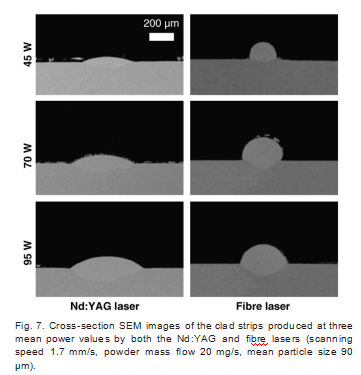
At a fixed processing speed, the aspect-ratio of the tracks generated by the Nd:YAG laser is considerably higher than that of the tracks generated by the fibre laser. When working with the fibre laser, higher scanning speed is required to obtain aspect-ratio values suitable for producing coatings by track overlapping [6]. For the same processing speed, the energy density (P/vD) of the Nd:YAG radiation is lower due to a wider spot than the one obtained by fibre radiation. As it is well known, this fact is a consequence of the better beam quality of the fibre laser. The higher energy density will allow catching more particles from the powder stream. Moreover, the reduced spot diameter of the fibre laser concentrates the energy in a smaller area, avoiding the molten pool spreading transversally to the scanning direction. The consequence of more molten precursor powder in a smaller area is the rapid growth of the clad height of the fibre laser tracks. This fact is well illustrated in Fig. 7 that shows the cross-section SEM images of the clad tracks produced by both types of lasers under similar conditions.

Regarding the dilution of the deposited tracks, the measured geometrical dilution (geometrical dilution was calculated according the following formula geom. dilut.= h2/(h+ h2), where h: clad height and h2: clad penetration depth, see Ref.[10]) was plotted as a function of the scanning speed (see Figs. 8 and 9). The geometrical dilution obtained from both laser sources shows a similar trend, and responds to the combined behaviour of the clad height and the penetration Fig. 10. Hardness mean values according to depth for Nd:YAG and fibre lasers (laser power 95 W, energy density 165 J/mm2).depth. For the Nd:YAG laser, logarithmic dependence of the proces- sing speed is observed, while for the fibre laser better fit was found with the combined parameter Pv. Most of the tested conditions lead to high geometrical dilution values due to the low spot diameter and the elevated energy density.


The hardness was found to slightly decrease when increasing the depth within the track cross-section (see Fig. 10); this behaviour is in good agreement with the higher presence of substrate elements diluted in the cladding material while getting closer to the interface. The zone below the interface presents hardness values to some extent higher than the substrate as received. The behaviour of the hardness across the cross-section is similar for both laser sources; mean hardness values obtained with the fibre laser are slightly superior when reaching a certain depth due to the higher fibre laser penetration on the substrate. The average values of the Young's modulus were 250 GPa for the tracks obtained with Nd:YAG laser and 290 GPa for the ones obtained with the fibre laser.
The laser cladding assisted by fibre laser revealed a wider processing window in terms of speed range in comparison with a conventional Nd:YAG laser. Clad tracks obtained under the same processing conditions are thicker and narrower than those produced by Nd:YAG laser. Nevertheless, dilution and penetration depth into the substrate are also higher. This fact is attributable to the better beam quality of the fibre laser beam. Similar hardness values were obtained for the tracks produced by both types of lasers.
Therefore, in the range of parameters studied in this work, it can be concluded that a high brightness laser is only recommended when very narrow clad tracks are required but not for regular wide tracks used for large coatings.
Acknowledgments
This work has been partially financed by the Spanish Government, (CICYT MAT2006-10481, DEX-560410-2008-169 and FPU program AP2006-03500 grant) and by Xunta de Galicia (PGIDIT06TMT00501CT, PGIDIT06PXIA303086IF, INCITE07PXI303112ES, and INCITE08E1-R30300ES). Assistance of the technical staff of CACTI (University of Vigo) is gratefully acknowledged.

 English
 Pусский