


Press Brake Machine Forming
In my journey through the world of metal fabrication, I have gained valuable insights into press brake machine forming. This process is essential for creating precise bends and shapes in various sheet metal materials. Understanding the intricacies of how a press brake machine operates allows me to achieve high-quality results while minimizing waste. In this article, I will explore the key elements of press brake machine forming, including techniques, best practices, and tips for enhancing efficiency in the bending process. My goal is to share knowledge that can benefit both beginners and seasoned professionals in the industry.
Overview of Press Brake Machine Forming
This section is focused on bending, the forming process most closely associated with the press brake.
Equipment Characteristics
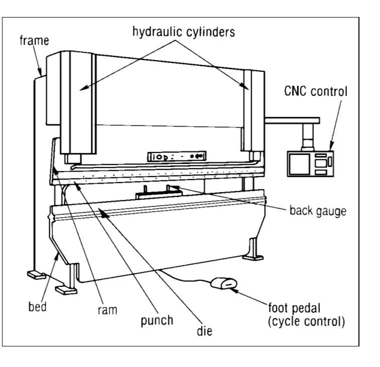
Press brake machine forming is usually in the capacity range of 20 to 200 tons with bed lengths ranging from 4 to 14 feet (1.2 m to 4.3 m). They may be powered by mechanical, hydraulic or mechanical hydraulic means. They may be “up-acting” or “down-acting,” depending on the direction of the ram’s power stroke. Figure 1 shows a down-acting CNC hydraulic press brake.
Press brake machine forming may be equipped with one of several types of back gauges, including manually placed and adjusted gauges, pins which engage holes in the workpiece and computer numerically controlled programmable units which adjust settings after each stroke.
Operation
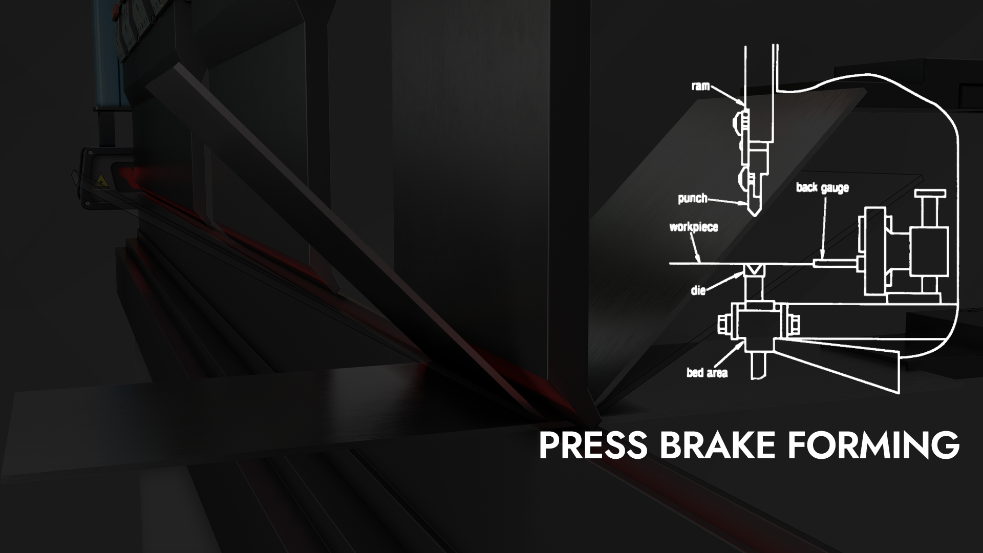
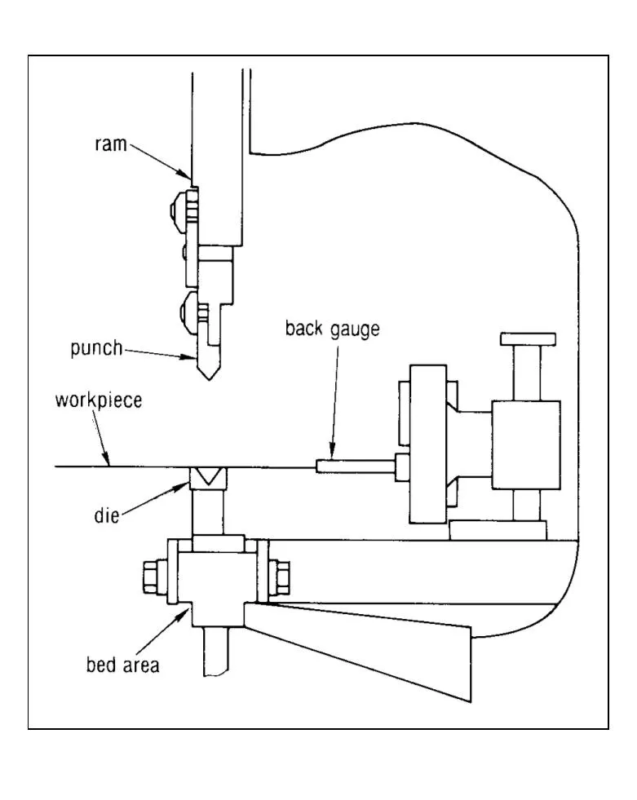
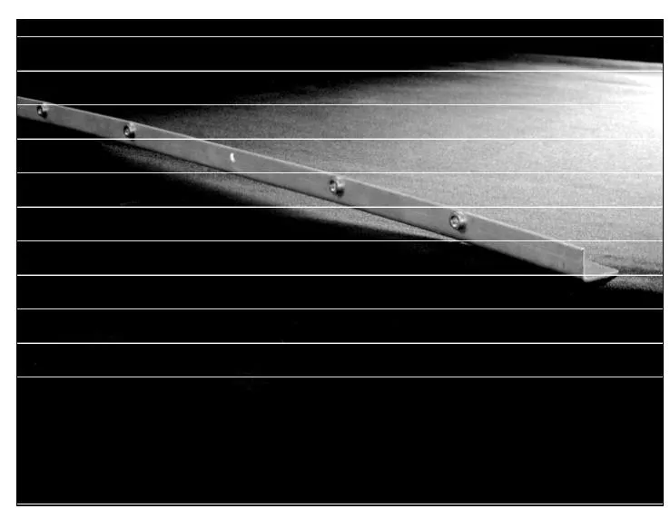
Most press brakes are manually fed. The operator holds the workpiece between the punch and die against the appropriate back gauge, providing the pre-set dimension for the bend (Figure 2).
Section of Press Brake Setup
Bottoming or Coining
When the blank is properly positioned the machine is activated causing the ram to move toward the bed, and the workpiece is formed between the die and punch. Then the ram returns, allowing for removal of the workpiece.
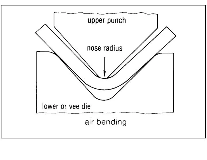
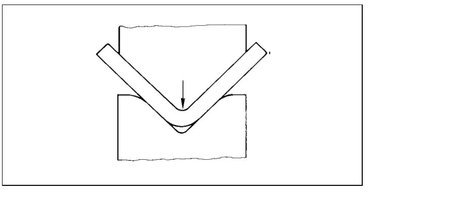
One type of press brake operation is air bending of sheet metal into a straight line angle. As shown in Figure 3, the punch pushes the workpiece into the die cavity. Throughout the entire operation, the workpiece touches only the tip of the punch and the two edges of the lower die. When the force of the upper die is released, the workpiece “springs back” to form a final angle. The amount of spring back is directly related to material type, thickness, grain and temper.

To minimize set-up time, most tools for air bending are made with the same angle in both the punch and die. Commonly an 80° or 85° die angle is used to allow for sufficient spring-back to obtain a 90° final angle.
Minimum Flange width Guidelines
In situations requiring dimensional accuracy and angular precision, another forming process is required (Figure 4). This process is called “Coining” or “Bottoming.” Coining requires having a punch and die manufactured to the desired final bend angle and forcing the work piece completely into the die. Coining reduces spring-back, however this process is limited by the tonnage capacity of the Press brake machine forming.
Advantages and Limitations
The fundamental advantage of the Press brake machine forming as a forming tool lies in its flexibility. The use of standard vee-dies allows economical set-ups and run times on small lots and proto-types. Almost any part size and formed shape can be accommodated with the standard tooling, eliminating the cost and lead time associated with press form tooling. Figure 5 depicts the complexity of parts that can be manufactured on a press brake.
Modern press brakes with programmable back gauges using multiple die set-ups, have made this forming process much more competitive for longer runs.
In cases where product designs require specially shaped tooling, press brake die costs and lead times are relatively modest.
The enormous range of workpiece sizes which can be accommodated in the press brake is another significant advantage. Size may be limited by the length of the ram and the ability to remove the workpiece from the machine after forming.
Since die changes are accomplished quickly, a variety of standard shapes can be created at modest cost, providing considerable flexibility in configuration of the final product. Since each bend is gauged separately, every bend or operation introduces the potential for an additional dimensional variation.

Design Considerations
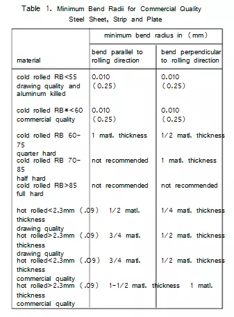
● Inside Press brake machine forming, a common radius should be specified for all bends on a part wherever possible, reducing costs and improving quality. Requirements for inside radii, which are less than the recommended minimum shown on Table 1, can create material flow problems in soft material and fracturing in hard material.
For further information on bend radii, see the Material Selection Chapter.
● Flange Size. The minimum flange width should be at least four times the stock thickness plus the bend radius (Figure 6). Requiring too narrow a flange can overload the equipment, distort the part and damage the tooling.
● Flange Spacing. A minimum distance between Press brake machine forming is required to accommodate the tooling. Spacing between bends, as for example in “U”-shaped contour, should be reviewed with the supplier prior to completion of the design, since dimensional repeatability can be difficult to maintain without dedicated tooling.
● “Run-Out” Flange. It is unrealistic to add intermediate dimensions to arrive at an overall dimension. Instead, it is practical and economically desirable to allow for an accumulation of dimensional variation in the least critical feature or bend on each axis. (These accumulations are often referred to as “stack-ups” and the feature absorbing the variation is commonly termed the “run-out” flange) (Figure 7). Note use of “obround” holes to accommodate tolerance accumulation.
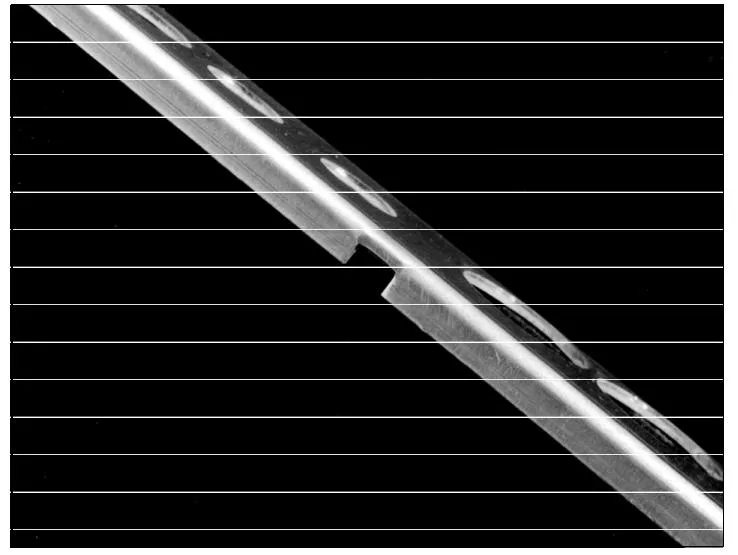
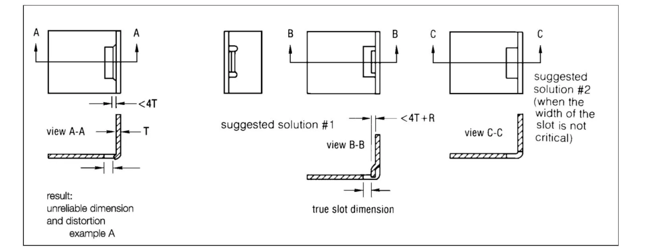
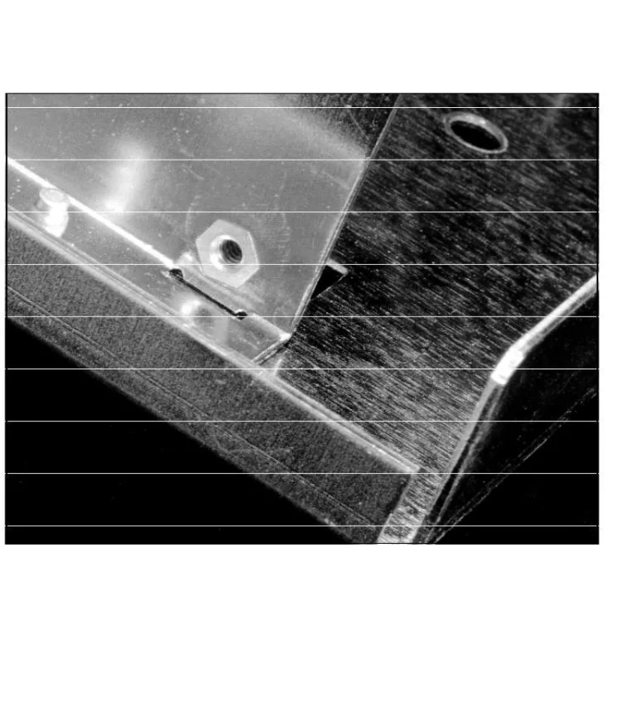
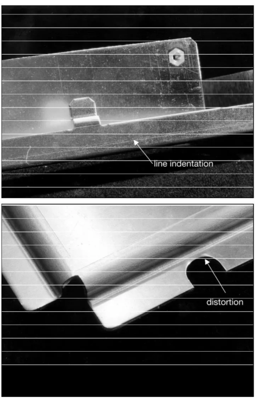
● Features at or Near Bends. Features such as holes, slots and certain notches should not be located closer than 3 stock thickness plus the bend radius from the bend. The result will cause a variety of problems including feature distortion and inability to seat clinch hardware(Figures 8, 9 and 10). If a feature must be nearer the bend than recommended, consider extending the opening past the bend line

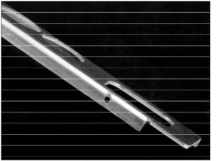
(Figures 11 and 12). If a slot dimension is functionally important use a feature as shown in Figure 11.
● Angularity. To assure repeatability in bend angles of less than 90° in single-bend vee-die operations it is often necessary to employ special processing and tooling—at additional cost.
The use of standard 90° bends wherever possible is preferable. Consistency of angles is affected by variations in material and press repeatability.
● Die Marks. Slight indentations on the outside (die side) of the workpiece (Figure 13) often result from contact with the top edges of the die during forming. These are inherent in the Press brake machine forming.
Dimensioning Practices
Practical experience has proven that dimensioning and measuring practices must both be understood and agreed on by all parties to achieve workable inspection parameters. To achieve consistent results when measuring formed parts, a standard has to be established on where and how dimensions are to be taken.
● Form dimensions should be measured immediately adjacent to the bend radius in order not to include any angular and flatness discrepancy. See Figure 14.
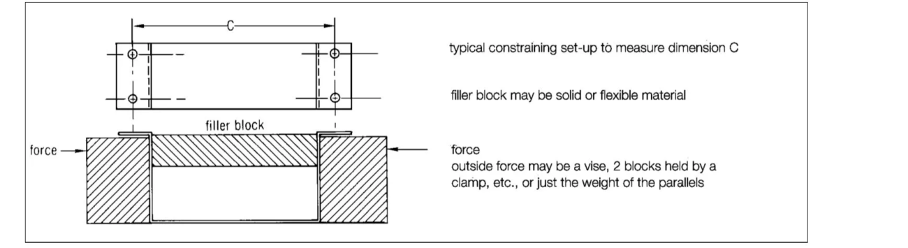
● Feature-to-feature dimensions on formed legs of any length on flexible parts will be assumed to be measured in constrained condition, holding the part fixtured to the prints’angularity specification. See Figure 15. This standard is appropriate for the majority of thin sheet metal parts and results in a functional product.
● Constraining methods vary from part to part, depending on shape and material condition. For large quantities, a measuring fixture is most practical for speed and repeatability. The relatively high cost is justified by the increased production rate and reliability gained.
The simplest constraining device is dead weight. Where applicable, the weight to be used during the measuring process should be specified, as well as the physical shape. Weight is most often used to eliminate a material out-of-flatness condition, sometimes in conjunction with an angular measurement.
.
As shown in Figure 15, parallel blocks by themselves, or with clamping devices, are probably the most often employed and practical constraints for occasional use, when legs need to be kept at 90° and parallel. In rare cases when restrained measurement is inappropriate, the drawing should reflect this requirement.
Such cases normally result in special manufacturing steps, which may add considerable cost.
In addition to these considerations, using the following guidelines will increase the manufacturability of designs for press brake forming.
Select a single datum close to an end of the part and maintain the same datum in all related

drawings (Figure 16). This datum should be a pierced feature in the principal flat surface of the part, selected on the basis of the sequence of bends. Early discussion with the supplier may be useful in selecting datums and dimensioning effectively.
For most economical production, dimension the part in a single direction wherever possible.
Because of the sequential nature of the forming process, and the fact that dimensional variation is introduced at each bend, dimensioning in a single direction parallels the process and helps to control tolerance accumulation.
It is generally recommended that dimensioning be done from a feature to an edge.
Feature-to-feature dimensions in two planes should be avoided. Feature-to-bend dimensions may require special fixtures or gauging.
Tolerances in the title block of a drawing may be unnecessarily restrictive for certain dimensions and angles, while very appropriate for others.
Almost any degree of precision can be achieved if cost is no object. For economical manufacturing, it is necessary to adopt dimensioning practices which consider the characteristics and limitations of the process and highlight truly critical dimensional relationships.

Spain-Customer-Feedback.jpg)

America-Customer-Feedback-1.jpg)
America-Miami-Customer-Feeback-1.jpg)
Uzbekistan-Customer-Feedback1.png)
Kosovo-Customer-Feedback11.png)
Russia-Customer-Feedback.jpg)
Russia-Customer-Feedback-3.jpg)


