


Correctly setting ESA S650 work data is crucial for safe, accurate, and repeatable bending operations. The work data section controls the ram’s top dead center (T.D.C.), bending force, hydraulic crowning, pinch point, mute point, bend time, speed, repetitions, and even special functions like pneumatic dies. If these parameters are not configured correctly, you may experience collision risks, inaccurate angles, excessive cycle times, or machine overload. In this guide, I’ll explain every field in the ESA S650 work data – what each value means, how to adjust it, and when to use advanced options like C.S.T., Match, and Repetitions. By the end, you’ll be able to set up a safe and efficient bending cycle for any job.
Understanding the Core Parameters of ESA S650 Work Data
The work data section is where you fine‑tune the behavior of the ram and backgauge during each bend. Correctly setting ESA S650 work data starts with mastering these essential fields. Every parameter in the ESA S650 work data has a specific role in the bending cycle.
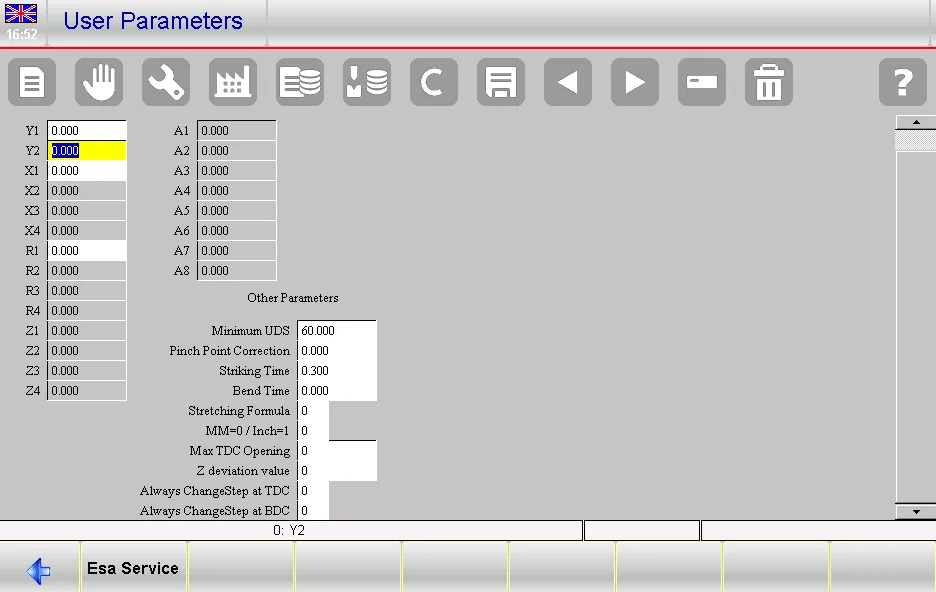
T.D.C. (Top Dead Center) – Safe Opening Height
T.D.C. defines how far the ram opens at the end of a bend (the space between the punch tip and the die edge). When configuring ESA S650 work data, a higher T.D.C. makes it easier to remove and reposition the workpiece, but increases cycle time.
- Range: 0.01 – 999.99 mm/inch
- توصية: Set to at least the material thickness + 20 mm for safe clearance. For thick plates or complex parts, increase further.
Force – Bending Tonnage
This is the force required to bend the sheet metal. Within ESA S650 work data, the control calculates an initial value based on material, thickness, and V‑die opening, but you can override it manually.
- Range: 0.1 – 9999.9 tons / short tons
- نصيحة: If the angle is consistently over‑bent, reduce force slightly; if under‑bent, increase force. However, for precise angle control, use Y‑axis corrections instead of force changes.
Crown. (Hydraulic Crowning) – Compensating for Deflection
If your press brake is equipped with hydraulic crowning, this field sets the percentage of maximum crowning force (0–100%) needed to straighten the machine’s base. Correctly setting ESA S650 work data for crowning ensures uniform angle across the entire workpiece length.
- تقصير: 0 (no crowning)
- Tuning: Run a test bend on a long workpiece and measure the angle at both ends and the center. Increase the crowning percentage if the center angle is too open.
C.S.T. (Change Step Time) – Delay Between Bends
This is a delay time (in seconds) between the completion of one bend and the movement of the backgauge for the next bend. In ESA S650 work data, C.S.T. gives the operator time to remove or reposition the workpiece manually.
- Range: 0 – 99.99 seconds
- Special value: 99 means the machine waits indefinitely until the operator presses “Down” to continue. Use this for complex manual handling.
Pinch Point – Adjusting the Clamping Position
The pinch point is the ram position where the workpiece is securely clamped before bending begins. This field adds an offset (positive or negative) to the calculated pinch point. When you set ESA S650 work data, a positive pinch point value increases the clamping height, which can help avoid material slip.
- Range: -99.99 to 999.99 mm/inch
- When to adjust: If the sheet slips during bending, increase the pinch point. If the punch hits the die too early, reduce it.
Mute – Speed Change Point Offset
The mute point is where the ram switches from fast approach to bending speed. This field offsets the calculated mute point. A positive value makes the speed change happen earlier (higher position), which can reduce cycle time but may increase collision risk.
- Range: -99.99 to 999.99 mm/inch
- Important: The order must always be: T.D.C. > Mute > Pinch point > L.D.C. If you break this order, the program will not run in automatic mode.
Bend Time – Holding at Lower Dead Center
The time (in seconds) that the ram remains at the lower dead center (L.D.C.) to allow the material to yield (especially for thick or springy materials). Longer bend time improves angle stability but increases cycle time.
- Range: 0 – 99.99 seconds
- Use case: For stainless steel or high‑strength materials, set 0.5–1 second. For soft aluminium, 0 is often sufficient.
Match – Controlled Rise Speed
The speed (m/min) at which the ram returns from L.D.C. to the pinch point after bending. A lower match speed prevents heavy plates from overturning toward the operator.
- Range: 0 – 10 m/min
- توصية: For thin sheets (≤2 mm), use 5–10 m/min. For heavy plates, reduce to 1–2 m/min for safety.
Speed – Bending Ram Speed
The speed at which the ram moves during the actual bending phase (from mute point to L.D.C.). Slower speeds give better angle accuracy, especially for air bending.
- Range: 0 – 10 m/min
- نصيحة: Start with 5 mm/s and decrease if you see angle overshoot or vibration.
Advanced Work Data Functions
Functions 1 to 20 – Special Output Management
These are ON‑OFF flags (0 or 1) that control external devices via the machine’s I/O. Function 2 is particularly important: when enabled, it manages pneumatic dies and folding bases, and allows the backgauge to move while the ram is still at T.D.C.
- To access functions not displayed: Refer to the “special functions” chapter of your machine manual. You may need to scroll or use a secondary menu.
Rep. (Repetitions) – Repeat the Same Bend
Number of times (1–99) that the current bend should be repeated before moving to the next bend. Useful for coining or when multiple hits are needed to achieve the final angle (e.g., large radius bumping).
- تقصير: 1
- مثال: Set Rep.=3 for a coining operation where each hit closes the angle by 2 degrees.
Direct – Insertion Direction (Graphic Programs Only)
This field is not used in numeric programs. For graphic programs, it defines the direction of sheet insertion (forward or backward). Values: -1, 0, 1. Leave at default unless you have a specific workholding requirement.
Ri (Internal Radius) – Calculated or Forced Radius
Shows the calculated internal radius of the bend. In a numeric program, changing Ri directly influences the development (blank length) calculation. In a graphic program, it shows the operator what radius will be obtained.
- Range: 0 – 9999.99 mm
- Caution: Modifying Ri in a numeric program will recalculate the stretch. Only do this if you know the exact radius from a test bend.
Step‑by‑Step – How to Correctly Set ESA S650 Work Data
Step 1 – Set Basic Safety Values
- T.D.C.: Material thickness + 20 mm (or more for deep boxes).
- قوة: Accept the calculated value initially.
- Crown.: Start at 0, adjust later if needed.
Step 2 – Configure Cycle Timing
- C.S.T.: 0 for automatic feed; 2–3 seconds if manual handling is required.
- Bend time: 0 for thin materials; 0.5–1 second for thick or springy materials.
- Match: 5 m/min for thin sheets, 1 m/min for heavy plates.
- سرعة: 5 mm/s as a starting point.
Step 3 – Fine‑Tune Ram Position Offsets
- Pinch point: Leave 0 unless material slips.
- صامت: Leave 0. If you want faster cycles, increase slightly, but verify the order T.D.C. > Mute > Pinch point > L.D.C. still holds.
Step 4 – Set Special Options if Needed
- الوظائف: Enable Function 2 for pneumatic dies.
- Repetitions: Set >1 only for coining or bumping.
- Ri: Only modify in numeric programs if you have precise radius data.
Step 5 – Test and Adjust
Run a test bend. If the angle is inconsistent, adjust Force or Y‑axis corrections (not recommended to change work data for angle issues). If the sheet slips, increase Pinch point. If the cycle feels too slow, carefully increase Speed and Mute.
الأسئلة الشائعة
What happens if I set Pinch point too high?
The ram may stop too early, and the bend will not complete. The machine may report a “Pinch point not reached” error. Always verify your ESA S650 work data after changes.
Why does my program not run in automatic mode?
Check that T.D.C. > Mute > Pinch point > L.D.C. If this sequence is violated, automatic execution is disabled. This is a common issue when setting ESA S650 work data.
How many Functions (1–20) can I use simultaneously?
As many as your machine’s I/O supports. However, each function is typically assigned to a specific hardware output. Consult your manual before modifying this part of ESA S650 work data.
خاتمة
Correctly setting ESA S650 work data ensures that every bend is performed safely, accurately, and efficiently. By understanding the role of T.D.C., Force, Crowning, Pinch point, Mute, C.S.T., Bend time, Match, Speed, Repetitions, and special Functions, you can tailor the machine’s behavior to the material and part geometry. Mastering ESA S650 work data allows you to start with conservative values and incrementally optimize after successful test bends. Remember the golden rule: T.D.C. > Mute > Pinch point > L.D.C. – breaking this order will stop automatic execution.
Now that you know how to correctly set ESA S650 work data, I encourage you to open a simple numeric program and experiment with changing the Mute offset (e.g., +5 mm) and observe how the ram speed change point moves. Practice setting C.S.T. to 2 seconds to give yourself time to handle the sheet. Correctly setting ESA S650 work data will become second nature with a little practice. If you need further assistance, our HARSLE technical يدعم team is ready to help you fine‑tune your work data for any application.


