


When creating precise metal bends and shapes, accurate input of drawing data is crucial. The ESA S650 Polar Setting function allows you to configure drawing segments using a simple, intuitive polar format. By understanding how to enter lengths and angles correctly, you can streamline the setup of your CNC press brake programs and reduce errors. In this article, I’ll guide you through the process of using ESA S650 Polar Setting effectively, so you can make your metalworking tasks faster and more accurate.
How to Configure ESA S650 Polar Setting for Accurate Drawing
Configuring the ESA S650 Polar Setting correctly ensures precise يلويs and efficient programming of your metalworking tasks. By following these steps, you can define each segment of your drawing clearly, minimizing errors and improving production quality.
Step 1: Understanding the Polar Setting Function
The ESA S650 Polar Setting function allows operators to input drawing segments using lengths and angles instead of absolute coordinates. This method is recommended for its simplicity and accuracy, especially when designing complex shapes or repeated parts. Each segment requires two parameters: the length of the side and the angle relative to the following segment, with angles ranging between ±180°.
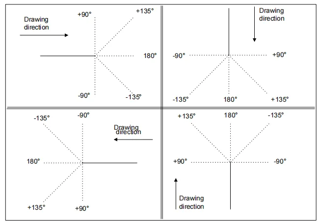
Using polar coordinates reduces the risk of misalignment between connected segments, and it allows easier visualization of the overall shape of the metal part. This is particularly useful when programming intricate bends, like Z-shaped or offset parts, where maintaining the relative angles is crucial.
Step 2: Accessing the Polar Setting on the ESA S650
To access the polar drawing mode:
- From the main Editor page, select the رسم وظيفة.
- Choose the option to enter data in Polar format.
- Review the existing segments to verify that all angles and lengths are consistent with the intended design.
Operators should ensure the screen resolution and scaling settings allow clear visibility of each segment while entering data. Correct use of the ESA S650 Polar Setting avoids errors that could occur if segments are misread due to a crowded interface.
Step 3: Entering Segment Data with Polar Coordinates
Once in the polar setting page:
- أدخل length of the current segment using the input field.
- أدخل زاوية relative to the following segment, ensuring it follows the ±180° convention.
- Verify the input by checking the preview of the segment displayed on the screen.
It’s important to double-check each angle immediately after entry. Small mistakes can propagate through the rest of the drawing, leading to incorrect bends. If a segment is not aligned properly, use the undo or edit functions before proceeding to the next segment.
Step 4: Optional Cartesian Input for Complex Designs
Although polar format is preferred, the ESA S650 also supports Cartesian input:
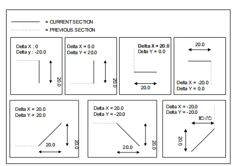
- Input the X and Y coordinate differences from the start to the end of each segment.
- Ensure all coordinates are relative to the beginning of the segment, not absolute positions.
Cartesian input is useful when precise coordinate mapping is required, such as when replicating parts from CAD drawings. However, polar input is generally faster and reduces cumulative errors when dealing with sequential bends.
Step 5: Entering General Data Before Drawing
Before starting your drawing:
- أدخل general data, including material thickness, resistance, and die selection.
- Set the V-die and punch for the program, ensuring they match the material specifications.
- Confirm that all general data entries are accurate to prevent calculation errors in the bend sequences.
General data acts as the foundation for the ESA S650 Polar Setting. Incorrect material thickness or die selection can lead to miscalculations in the bending sequence and final product dimensions.
Step 6: Reviewing, Adjusting, and Saving the Drawing
After entering all segments:
- Review the full drawing to check for missing or incorrect angles and lengths.
- Adjust segments as necessary to achieve the intended shape.
- Save the program for execution, ensuring all polar data is stored correctly in the CNC system.
Regularly saving your work during drawing input is crucial, especially for long programs. The ESA S650 Polar Setting allows you to store intermediate steps, reducing the risk of losing data in case of power interruptions or system errors.
Step 7: Practical Tips for ESA S650 Polar Setting
- Always start with simple shapes to familiarize yourself with polar input.
- Use the preview function to visualize bends before executing the program on metal.
- Keep a log of material properties and die configurations for repeated jobs to ensure consistency.
- For complex multi-segment drawings, consider breaking the drawing into sections to avoid input errors.
By following these steps, the ESA S650 Polar Setting can significantly enhance productivity and accuracy in sheet metal bending.
الأسئلة الشائعة
Can I switch between polar and Cartesian input for the same drawing?
Yes, the ESA S650 allows switching between polar and Cartesian formats. However, it’s recommended to stick with one format per drawing to avoid inconsistencies in segment angles and lengths.
How do I correct a segment if I entered wrong values?
Use the undo or edit function on the polar setting page to adjust the segment before proceeding to the next one. Always verify the segment preview before continuing.
Does changing general data affect previously entered polar segments?
No. Changing general data (like material thickness or die selection) will not automatically alter existing segments. However, incorrect general data can lead to miscalculations during program execution.
خاتمة
Using the ESA S650 Polar Setting effectively ensures precise and efficient drawing of all segments in your metalworking programs. By entering the correct lengths and angles, verifying each segment, and combining them with accurate general data, you can minimize errors and maintain consistent bend quality. Polar input simplifies complex designs, improves accuracy, and allows for easier adjustments compared to Cartesian coordinates.
For best results, always review your drawing before execution, save the program frequently, and make adjustments using the undo or edit functions when necessary. For more detailed guidance or troubleshooting, contact HARSLE’s support team to ensure your ESA S650 programs achieve maximum precision and efficiency.


